Wiring Diagram Reality Check For PID

Homebrew Talk - Beer, Wine, Mead, & Cider Brewing Discussion Forum

Help Support Homebrew Talk - Beer, Wine, Mead, & Cider Brewing Discussion Forum:

This site may earn a commission from merchant affiliate links, including eBay, Amazon, and others.

IndyBlueprints

Well-Known Member
Joined
Oct 30, 2010
Messages
140
Reaction score
54
Location
Indy
Hey Guys,

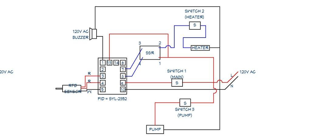
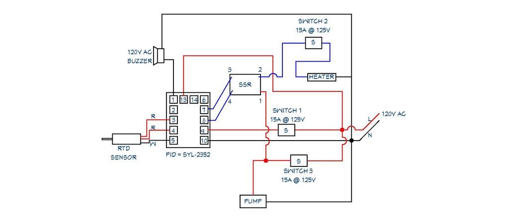
I am a rookie with wiring diagrams, so I need a little direction. I have a single PID (SYL-2352) running a RIMS tube. What I'm trying to set up is a box with 3 switches. The first switch will turn the whole system on. The second switch will allow the SSR to bring power to the heating element. The third switch will allow me to manually switch on the circulating pump.

I have a 5,000W 240V heating element running on 120V, so effectively 1,375W @ 120V.

My switches are Radio Shack DPDT Heavy Duty Toggle Switches rated at 10A @ 125V AC.

My first question is, are these switches strong enough for the job?

My second question is, Does my wiring diagram look right?
PID%20PROPOSED_1.jpg
 
Last edited:
I think I already see an issue. I think the heater switch should be in between terminal #2 on the SSR and the heater?
 
Well, I did get some additional information; If my heating element is 1,375W, it's about 11.4A, so I need a 15A toggle switch.

Other than that, I guess I'm going to wire it as is, and see if it works.
 
Switch 1 is only switching power to the PID. If you want it to act like a main power switch it should be the first device the incoming line hits. After that switch, it would split towards
1. the PID power terminal,
2. towards the element that should first hit the element power switch and then the SSR after that switch. There is no reason to give the SSR power when you want the element off.

If you would like to interlock the heater function with the pump such that the pump must be running before you can fire the RIMS element, you just need to feed the element enable switch, and downstream circuit, SSR etc from load side of the pump switch. That means you can run the pump by itself or run the pump AND the element if the element enable switch is closed AND the PID is calling for heat.
 
I have modified it slightly. My thought is to have the pump before the PID switch so I can run the pump with nothing else being turned on:

PID%20PROPOSED%206.jpg
 
How's this work out for you? I'm also looking into doing this. Starting to gather the parts for the controller at the moment
 
Any chance the pictures could be uploaded again? I had the set up from this thread but went to build into a new box and forgot label everything. If unable that's okay.
 
Any chance the pictures could be uploaded again? I had the set up from this thread but went to build into a new box and forgot label everything. If unable that's okay.
Here's the final diagram

PID PROPOSED 7.jpg
 

Attachments

  • PID PROPOSED 7.jpg
    PID PROPOSED 7.jpg
    28.7 KB · Views: 108

Latest posts

Back
Top