Wiring a 240V 22mm LED as Element Indicator (Am I doing it right?)

Homebrew Talk - Beer, Wine, Mead, & Cider Brewing Discussion Forum

Help Support Homebrew Talk - Beer, Wine, Mead, & Cider Brewing Discussion Forum:

This site may earn a commission from merchant affiliate links, including eBay, Amazon, and others.

aquaman02

Well-Known Member
Joined
Jul 20, 2017
Messages
52
Reaction score
7
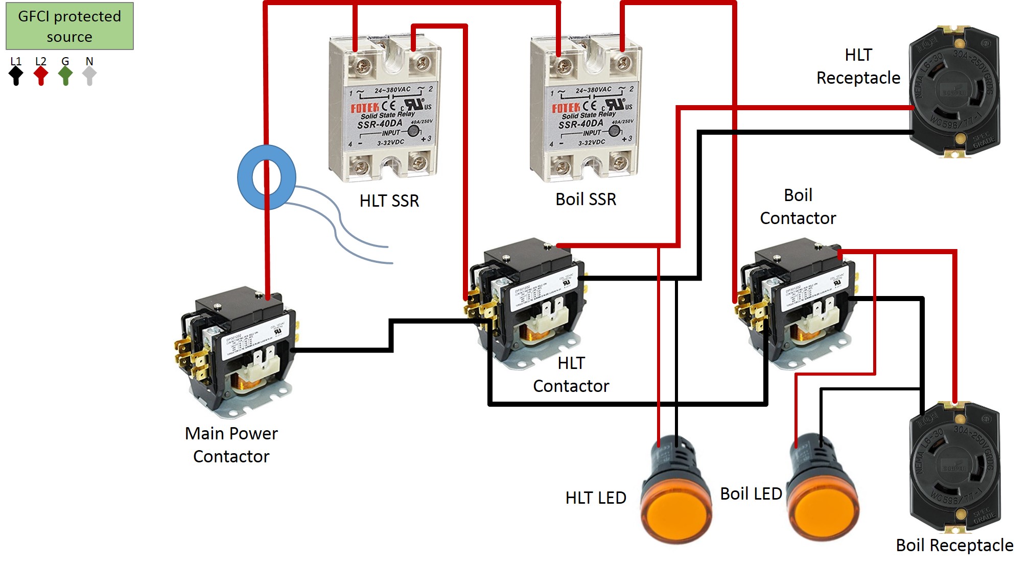
I am completing my wiring of the AUBER CUBE but am wiring a 240V 22mm yellow LED indicator to show me when the element is working. My question is do I wire it on a separate smaller wire directly from the SSR output, the same spot my 10ga wire goes to the Element. That would be the red wire. Where would my black lead (The other 120V) wire need to come from?
 
Wiring to 240V LED.jpg
What exactly do you mean by run it in parallel. Does that mean a separate wire directly to the LED.

Or, do I run my thicker 10ga wire from the SSR to the LED, then to the element. Also, where does the other leg need to come from (Black Wire)?
 
Last edited:
or if the ssr is wired after the contactor as many including myself like to do the the led still needs to be wired off of both hot lines but not directly inline if that makes sense, you dont want the actual cables carrying the power to the element to go to the led and from it to the element but rather smaller gauge wires or at least the same size pigtailed wires coming off of connection points feeding the element which you want to monitor.
 
View attachment 576033 What exactly do you mean by run it in parallel. Does that mean a separate wire directly to the LED.

Or, do I run my thicker 10ga wire from the SSR to the LED, then to the element. Also, where does the other leg need to come from (Black Wire)?
separate wire along side the main wires (in parallel with them). Think of the led as a volt meter, when you connect the two probes on the testpoint the meter tells you if theres power or not right? same thing here. in choice #2 the other wire needs to go to the other hot wire going to the element. (should be black)
 
I do not have contactors but I do have a circuit breaker inline with the 30A 240V power input on my Auber Cube. Auber says to wire from the circuit breaker (Black Wire) directly to the element. The Red wire goes from the breaker to the SSR. Then out from the SSR to the Element. Since the Black wire is going directly to the element, isn't it getting contstant 120V? That means the Element and LED will be getting 120V right? It will only see the 240V when switched on from the SSR. Am I not correct?
 
I do not have contactors but I do have a circuit breaker inline with the 30A 240V power input on my Auber Cube. Auber says to wire from the circuit breaker (Black Wire) directly to the element. The Red wire goes from the breaker to the SSR. Then out from the SSR to the Element. Since the Black wire is going directly to the element, isn't it getting contstant 120V? That means the Element and LED will be getting 120V right? It will only see the 240V when switched on from the SSR. Am I not correct?
That will work
 
If the black 120v leg is constantly wired to the element, is it and the led essentially always on but under powered?
 
If the black 120v leg is constantly wired to the element, is it and the led essentially always on but under powered?
no, the circuit is incomplete without a return path for the voltage.

for example on a regular 120v light a switch only switches the continuity of one wire to the light. whether its the neutral or the hot your switching the light will still go off. If you have no contactors wired in your panel now you still have 120v going to your elements at all times too right? they are off until the power is added to the other leg completing the circuit.

normally contactors are added to remove this possible safety concern since if you have elements with TC adaperts and plugs at the element for example and go to unplug it while its wet or you have wet hands thinking its off you can still get zapped from the 120v thats always hot to one leg. also SSRS leak voltage while mainly limiting current so the light may always be on but very dim depending on the SSR used in your panel.

on my first panel the cheap knock off foteks I used caused the lights to glow when ever the contactor was on regardless of ssr state it would just flash dimmer and brighter until I removed power by shutting off the contactor with my element selector switch.
 
Great. Thank you for clearing that up. Should I put a 15A fuse inline with the LED?
 
Great. Thank you for clearing that up. Should I put a 15A fuse inline with the LED?
I added more info in an edit above... I would use something as small as 1/4 amp if your going to ad a fuse but it really depends on the size of wire you use to feed the led as that determines the largest fuse you can use... the led wont even use close to 1/4 amp so...
 
I am using 16ga wire to the LED. What size fuse. It is a 240v LED. Is using 16g way overkill or does it even matter? If it only draws <2W according to Auber, do I even need a fuse?
 
Last edited:
I am using 16ga wire to the LED. What size fuse. It is a 240v LED. Is using 16g way overkill or does it even matter? If it only draws <2W according to Auber, do I even need a fuse?
i wouldnt bother with 16awg wire if it were me but its up to you really unless your having it inspected?
 
I have extra so no big deal. I tend to over build everything anyway.
 
When I turn my main power on the element LED is illuminated. I wired it directly off of the element. Why is it on?
 
Last edited:
When I turn my main power on the element LED is illuminated. I wired it directly off of the element. Why is it on?

I assume that you don't have the heating element plugged in? My system does the same thing when I unplug any of the elements connected to the control panel. The reason is that SSR's leak a bit of current. When the element is unplugged, there is enough current to dimly light the LED. The element sucks all the current leakage when its plugged in.

I also used 240v LEDs that are wired directly across the output terminals on my SSRs. They light when the SSR is sending 'real' current to the element.
 
Ok. Yes, my element is not plugged in at the moment. Just finished making the main power cable and put juice to it to make sure all the smoke stayed in the wires.
 
Just run a wire from each “hot” leg of the element plug to the light. This will signal the light whenever power is supplied to the element letting you know.
 
You’re scaring me—240V can be lethal. There is more than 1 way to get 240V on 2 wires, which depends on how you connect to the mains supply. So two things: it’s a must to have a GFCI breaker on the supply into your control box and the main power contactor should be “right there” (next in line), switching both of the lines used to power the heater. From the contactor, power your SSR and heater.
 
no, the circuit is incomplete without a return path for the voltage.

for example on a regular 120v light a switch only switches the continuity of one wire to the light. whether its the neutral or the hot your switching the light will still go off. If you have no contactors wired in your panel now you still have 120v going to your elements at all times too right? they are off until the power is added to the other leg completing the circuit.

normally contactors are added to remove this possible safety concern since if you have elements with TC adaperts and plugs at the element for example and go to unplug it while its wet or you have wet hands thinking its off you can still get zapped from the 120v thats always hot to one leg. also SSRS leak voltage while mainly limiting current so the light may always be on but very dim depending on the SSR used in your panel.

on my first panel the cheap knock off foteks I used caused the lights to glow when ever the contactor was on regardless of ssr state it would just flash dimmer and brighter until I removed power by shutting off the contactor with my element selector switch.
Your black or red is NOT your return path to the panel. That is only a neutral (white). If it's seeing one wire, it's getting constant 120v. Then when it sees the other one it's getting 240v. I'm a licensed electrician. Please don't play around with this stuff unless you're sure.

Sent from my XT1650 using Home Brew mobile app
Yes your correct I knew that, not sure why I posted it may have had 120v on the brain... You still need to complete the circuit with the second wire. My mistake has no bearing on the wiring advice given to run in parallel with the element power wires..
 
Last edited:
I assume that you don't have the heating element plugged in? My system does the same thing when I unplug any of the elements connected to the control panel. The reason is that SSR's leak a bit of current. When the element is unplugged, there is enough current to dimly light the LED. The element sucks all the current leakage when its plugged in.

I also used 240v LEDs that are wired directly across the output terminals on my SSRs. They light when the SSR is sending 'real' current to the element.
As I mentioned above if the OP is using crap ssrs like the knock off foteks the led will light dim as long as theres power reaching the main hot wires at the ssr because the foteks leak a lot of voltage. the leds will get noticeably brighter when the srrs is in the active state.like you said though the leds should turn off when the elements are connected. They didnt on my panel because I had contactors and a selector switch which killed the connection to the elements.. I also had the ssrs wired before the contactors which is something I no longer do.

I've not heard the OP mention what kind of ssrs hes using but im going to guess the cheapest ones he could find? aka fake foteks.
 
Last edited:
Using this:
Description: 40A SSR
Manufacture AUBER
Control Voltage 3-32VDC
Control Current DC3-25mA
Operating Voltage 24-480VAC
Current Rating 40A
 
It would help to see your wiring diagram. I'm still wondering whether you have a GFCI in there and whether you have accounted for neutral vs safety ground. On my control box I have the main contactor powered by the GFCI but also have an emergency off ("slam button") to kill power to the contactor. (Otherwise the contactor is always powered.)

upload_2018-6-23_7-41-34.png


From the diagram above you can see a 4-wire supply. Either of the "load" wires (red or black) will have 120V relative to the white neutral, so both red and black must be considered hot. Using both hot wires gets you 240V. Black wire to the element means that the element has a voltage on it all the time (relative to ground or neutral), even if the SSR is not switched on to complete the 240V circuit. If a liquid (or you!) connect that black wire to ground, you want the GFCI to trip.

I hope this helps. Apologies if this is already part of your build and I'm pointing out the obvious. Just thinking safety first.
 
Got everything figured out. Got the LED wired in parallel with the element. Shows faint light when system turned on but that is with the element unplugged. Other than that, system seems to check out fine so far. Still need to make up the element cable and then do a test run with water.
 
Back
Top