• Please visit and share your knowledge at our sister communities:
  • If you have not, please join our official Homebrewing Facebook Group!

    Homebrewing Facebook Group

[Version 2 Release] RaspberryPints - Digital Taplist Solution

Homebrew Talk

Help Support Homebrew Talk:

This site may earn a commission from merchant affiliate links, including eBay, Amazon, and others.
in the admin Display on the taps screen. there is a check box on top that says Show Pin Settings. That shows the Count per gallon.

There is also a calibrate button per tap. that will allow you to see the last pour information then adjust the actual pour volume. that will adjust the count per oz. I suggest doing 1 then coping the value to the rest unless you really have different meters or flow rates
Thanks again, as I haven't assembled everything yet I can't adjust it yet.
 
the board should have each pin position labelled
a standard connection is like this
SDA --> 24

SCK --> 23

MOSI --> 19

MISO --> 21

GND --> 6

RST --> 22 (this can be any regular pin but whatever pin you put it on needs to be configured in RPints)

3.3V --> 1
 
RFID Qustions

What is the Mug Id?

Where I find the RFID TAG?

1753487800166.png


1753487900793.png
 
What is the Mug Id?

Where I find the RFID TAG?
Mug Id is for places that offer a mug club. more of info field then anything

If there are RFID that were read but not assigned they will show up under the RFID textboxes as unassigned RFID in a drop down.

If you dont see them check /var/log/rpints.log for errors. You may need to change /python/Config.py

config['flowmon.debug' ] = False#True
to

config['flowmon.debug' ] = True

then restart the flowmon service and check the log again
Where can I find the the file /python/Config.py

1753544110399.png


1753544154882.png


1753543886324.png
 
RFID Woking now :rock:

Next challenge VALVE/SOLENOID

1) I chose pin 8, is it on Alamode(Arduino R3) or Raspberry Pi board?

2) I clicked "Let it Flow" changed to "Stop Flow" but when I save, it is back to "Let it Flow"
1753553078819.png

1753552891026.png


1753552920918.png
 
valve pins are based on the Valve PI Pin checkbox. if checked then its on the pi. if not checked then its on the Arduino.

let it flow doesnt require saving. if you click it the valves should open. Click it again to stop. Im not sure if looks up the state when the page loads to display it correctly
 
what is in the /var/log/rpints.log file? it may have some clues
I rebuilt all connections last night, now the Valve (LED for now) are working.

So LED is always ON, after RFID LED tun OFF, after I por LED tun ON.

I want to understand this Sendint Status. What do these letters and numbers mean?

;N;-1;0;0;0;|
U;2;2;251
N;-1;0;0;0;|
P;2;2;378
Y;2;0;0;0;|

1753725692226.png
 
C = configuration and only happens on startup
P = Pour
Y/N = RFID status Y means there was a RFID Read and the next number is the user or -1 if N
 
If I change to RPI Pin 3, no error, the LED does not change status, always OFF.

1753729525290.png

1753729367817.png
 

Attachments

  • 1753728618343.png
    1753728618343.png
    5.3 KB
  • 1753728844499.png
    1753728844499.png
    68.2 KB
Last edited:
what pin 3 are you using? the board pin 3 or the GPIO pin 3? Rpints uses Broadcom pin-numbering scheme so pin 3 is actually pin 5. but if you connect it to pin 3 thats SDA which isnt available to use for RPints
 
Sorry Is a little bi confused.

I am using RPi 4b, pins below are used.

RPi 4b - RFID READER
PIN 24(GPIO8) - PIN 8 (SDA)
PIN 23(GPIO11) - PIN 7 (SCK)
PIN 19(GPIO10) - PIN 6 (MOSI)
PIN 21(GPIO9) - PIN 5 (MISO)
PIN 6(GROUND) - PIN 3 GND
PIN 22 (GPIO25) - PIN 2 RST
PIN 1 (3V3) - PIN 1 (3.3V)

So, may I use PIN 11 (GPIO17) and PIN 13 (GPIO27) ?

1753734026522.png
 
Sorry Is a little bi confused.

I am using RPi 4b, pins below are used.

RPi 4b - RFID READER
PIN 24(GPIO8) - PIN 8 (SDA)
PIN 23(GPIO11) - PIN 7 (SCK)
PIN 19(GPIO10) - PIN 6 (MOSI)
PIN 21(GPIO9) - PIN 5 (MISO)
PIN 6(GROUND) - PIN 3 GND
PIN 22 (GPIO25) - PIN 2 RST
PIN 1 (3V3) - PIN 1 (3.3V)

So, may I use PIN 11 (GPIO17) and PIN 13 (GPIO27) ?

View attachment 881016

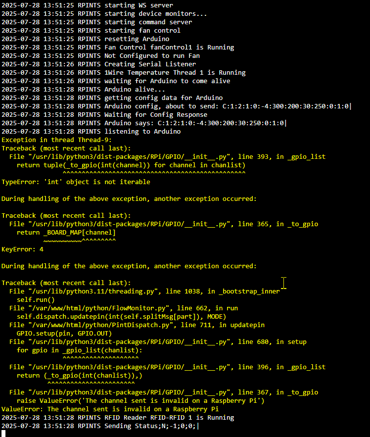
Is not working, please see below the error from a CONFIG FILE

RPI 4B GPIO 27 - PIN 7 - Not working
Exception in thread Thread-9:
Traceback (most recent call last):
File "/usr/lib/python3/dist-packages/RPi/GPIO/__init__.py", line 393, in _gpio_list
return tuple(_to_gpio(int(channel)) for channel in chanlist)
^^^^^^^^^^^^^^^^^^^^^^^^^^^^^^^^^^^^^^^^^^^^^^^^
TypeError: 'int' object is not iterable

During handling of the above exception, another exception occurred:

Traceback (most recent call last):
File "/usr/lib/python3/dist-packages/RPi/GPIO/__init__.py", line 365, in _to_gpio
return _BOARD_MAP[channel]
~~~~~~~~~~^^^^^^^^^
KeyError: 27

During handling of the above exception, another exception occurred:

Traceback (most recent call last):
File "/usr/lib/python3.11/threading.py", line 1038, in _bootstrap_inner
2025-07-30 20:55:11 RPINTS RFID Reader RFID-RFID 1 is Running
2025-07-30 20:55:11 RPINTS Sending Status;N;-1;0;0;|
self.run()
File "/var/www/html/python/FlowMonitor.py", line 662, in run
self.dispatch.updatepin(int(self.splitMsg[part]), MODE)
File "/var/www/html/python/PintDispatch.py", line 711, in updatepin
GPIO.setup(pin, GPIO.OUT)
File "/usr/lib/python3/dist-packages/RPi/GPIO/__init__.py", line 680, in setup
for gpio in _gpio_list(chanlist):
^^^^^^^^^^^^^^^^^^^^
File "/usr/lib/python3/dist-packages/RPi/GPIO/__init__.py", line 396, in _gpio_list
return (_to_gpio(int(chanlist)),)
^^^^^^^^^^^^^^^^^^^^^^^
File "/usr/lib/python3/dist-packages/RPi/GPIO/__init__.py", line 367, in _to_gpio
raise ValueError('The channel sent is invalid on a Raspberry Pi')
ValueError: The channel sent is invalid on a Raspberry Pi
2025-07-30 20:55:11 RPINTS Sending Status;N;-1;0;0;|
---------------------------------

RPI 4B GPIO 17 - PIN 6 - Not working
Exception in thread Thread-13:
Traceback (most recent call last):
File "/usr/lib/python3/dist-packages/RPi/GPIO/__init__.py", line 393, in _gpio_list
return tuple(_to_gpio(int(channel)) for channel in chanlist)
^^^^^^^^^^^^^^^^^^^^^^^^^^^^^^^^^^^^^^^^^^^^^^^^
TypeError: 'int' object is not iterable

During handling of the above exception, another exception occurred:

Traceback (most recent call last):
File "/usr/lib/python3/dist-packages/RPi/GPIO/__init__.py", line 365, in _to_gpio
return _BOARD_MAP[channel]
~~~~~~~~~~^^^^^^^^^
KeyError: 17

During handling of the above exception, another exception occurred:

Traceback (most recent call last):
File "/usr/lib/python3.11/threading.py", line 1038, in _bootstrap_inner
self.run()
File "/var/www/html/python/FlowMonitor.py", line 662, in run
self.dispatch.updatepin(int(self.splitMsg[part]), MODE)
File "/var/www/html/python/PintDispatch.py", line 711, in updatepin
GPIO.setup(pin, GPIO.OUT)
File "/usr/lib/python3/dist-packages/RPi/GPIO/__init__.py", line 680, in setup
for gpio in _gpio_list(chanlist):
^^^^^^^^^^^^^^^^^^^^
File "/usr/lib/python3/dist-packages/RPi/GPIO/__init__.py", line 396, in _gpio_list
return (_to_gpio(int(chanlist)),)
^^^^^^^^^^^^^^^^^^^^^^^
File "/usr/lib/python3/dist-packages/RPi/GPIO/__init__.py", line 367, in _to_gpio
raise ValueError('The channel sent is invalid on a Raspberry Pi')
ValueError: The channel sent is invalid on a Raspberry Pi
2025-07-30 20:56:58 RPINTS RFID Reader RFID-RFID 1 is Running
2025-07-30 20:56:58 RPINTS Sending Status;N;-1;0;0;|
 
RPI 4B GPIO 22 - PIN 8 - Not working - NO ERROR - LED STIIL OFF

I read RPI GPIO status by this command pinctrl get


rpints@rpints:~ $ pinctrl get
0: ip pu | hi // ID_SDA/GPIO0 = input
1: ip pu | hi // ID_SCL/GPIO1 = input
2: ip pu | hi // GPIO2 = input
3: ip pu | hi // GPIO3 = input
4: ip pn | hi // GPIO4 = input
5: ip pu | hi // GPIO5 = input
6: ip pu | hi // GPIO6 = input
7: op -- pu | hi // GPIO7 = output
8: op -- pu | hi // GPIO8 = output
9: a0 pd | lo // GPIO9 = SPI0_MISO
10: a0 pd | lo // GPIO10 = SPI0_MOSI
11: a0 pd | lo // GPIO11 = SPI0_SCLK
12: ip pd | lo // GPIO12 = input
13: ip pd | lo // GPIO13 = input
14: ip pn | hi // GPIO14 = input
15: ip pu | hi // GPIO15 = input
16: ip pd | lo // GPIO16 = input
17: ip pd | lo // GPIO17 = input
18: op -- pn | lo // GPIO18 = output
19: ip pd | lo // GPIO19 = input
20: ip pd | lo // GPIO20 = input
21: ip pd | lo // GPIO21 = input
22: ip pd | lo // GPIO22 = input
23: ip pd | lo // GPIO23 = input
24: ip pd | lo // GPIO24 = input
25: op -- pn | hi // GPIO25 = output
26: ip pd | lo // GPIO26 = input
27: ip pd | lo // GPIO27 = input
28: a5 pu | hi // RGMII_MDIO/GPIO28 = RGMII_MDIO
29: a5 pd | lo // RGMIO_MDC/GPIO29 = RGMII_MDC
30: a3 pu | lo // CTS0/GPIO30 = CTS0
31: a3 pn | lo // RTS0/GPIO31 = RTS0
32: a3 pn | hi // TXD0/GPIO32 = TXD0
33: a3 pu | hi // RXD0/GPIO33 = RXD0
34: a3 pn | lo // SD1_CLK/GPIO34 = SD1_CLK
35: a3 pu | hi // SD1_CMD/GPIO35 = SD1_CMD
36: a3 pu | hi // SD1_DATA0/GPIO36 = SD1_DAT0
37: a3 pu | hi // SD1_DATA1/GPIO37 = SD1_DAT1
38: a3 pu | hi // SD1_DATA2/GPIO38 = SD1_DAT2
39: a3 pu | hi // SD1_DATA3/GPIO39 = SD1_DAT3
40: a0 pn | lo // PWM0_MISO/GPIO40 = PWM1_0
41: a0 pn | lo // PWM1_MOSI/GPIO41 = PWM1_1
42: op -- pu | lo // STATUS_LED_G_CLK/GPIO42 = output
43: ip pu | hi // SPIFLASH_CE_N/GPIO43 = input
44: ip pu | hi // SDA0/GPIO44 = input
45: ip pu | hi // SCL0/GPIO45 = input
46: ip pu | lo // RGMII_RXCLK/GPIO46 = input
47: ip pu | lo // RGMII_RXCTL/GPIO47 = input
48: ip pd | lo // RGMII_RXD0/GPIO48 = input
49: ip pd | lo // RGMII_RXD1/GPIO49 = input
50: ip pd | lo // RGMII_RXD2/GPIO50 = input
51: ip pd | lo // RGMII_RXD3/GPIO51 = input
52: ip pd | lo // RGMII_TXCLK/GPIO52 = input
53: ip pd | lo // RGMII_TXCTL/GPIO53 = input
54: ip pd | lo // RGMII_TXD0/GPIO54 = input
55: ip pd | lo // RGMII_TXD1/GPIO55 = input
56: ip pd | lo // RGMII_TXD2/GPIO56 = input
57: ip pd | lo // RGMII_TXD3/GPIO57 = input
 
looks to me that the pin number its trying to update is not a valid integer. Can you puts the part of the log that traces the configuration, it should start with
Arduino config, about to send: C:

If you dont see it turn on the Debug option and restart Flowmon
in python/Config.py change line
config['flowmon.debug' ] = False#True
to
config['flowmon.debug' ] = True
 
Please see below

RPI 4B GPIO 27 - PIN 7

#logging settings for flowmon
config['flowmon.debug' ] = True

2025-07-31 19:54:08 RPINTS resetting alamode to try to force it to listen to us...
2025-07-31 19:54:09 RPINTS giving it a short break to wake up again...
2025-07-31 19:54:11 RPINTS reflashing Arduino via:
/var/www/html//arduino/avrdude/avrdude64 -C/var/www/html//arduino/avrdude/avrdude.conf -patmega328p -carduino -P/dev/ttyACM0 -b115200 -D -Uflash:w:/var/www/html//arduino/raspberrypints/raspberrypints.cpp.hex:i
2025-07-31 19:54:16 RPINTS Reading 11056 bytes for flash from input file raspberrypints.cpp.hex
Writing 11056 bytes to flash
Writing | ################################################## | 100% 1.80s
Reading | ################################################## | 100% 1.43s
11056 bytes of flash verified

Avrdude64 done. Thank you.

2025-07-31 19:54:16 RPINTS starting WS server
2025-07-31 19:54:16 RPINTS starting device monitors...
2025-07-31 19:54:16 RPINTS starting command server
2025-07-31 19:54:16 RPINTS starting fan control
2025-07-31 19:54:16 RPINTS resetting Arduino
2025-07-31 19:54:16 RPINTS Fan Control fanControl1 is Running
2025-07-31 19:54:16 RPINTS Not Configured to run Fan
2025-07-31 19:54:17 RPINTS Creating Serial Listener
2025-07-31 19:54:17 RPINTS 1Wire Temperature Thread 1 is Running
2025-07-31 19:54:17 RPINTS waiting for Arduino to come alive
2025-07-31 19:54:19 RPINTS Arduino alive...
2025-07-31 19:54:19 RPINTS getting config data for Arduino
2025-07-31 19:54:19 RPINTS Arduino config, about to send: C:1:2:1:0:-27:300:200:30:250:0:1:0|
2025-07-31 19:54:19 RPINTS Waiting for Config Response
2025-07-31 19:54:19 RPINTS Arduino says: C:1:2:1:0:-27:300:200:30:250:0:1:0|
2025-07-31 19:54:19 RPINTS listening to Arduino
Exception in thread Thread-9:
Traceback (most recent call last):
File "/usr/lib/python3/dist-packages/RPi/GPIO/__init__.py", line 393, in _gpio_list
return tuple(_to_gpio(int(channel)) for channel in chanlist)
^^^^^^^^^^^^^^^^^^^^^^^^^^^^^^^^^^^^^^^^^^^^^^^^
TypeError: 'int' object is not iterable

During handling of the above exception, another exception occurred:

Traceback (most recent call last):
File "/usr/lib/python3/dist-packages/RPi/GPIO/__init__.py", line 365, in _to_gpio
return _BOARD_MAP[channel]
~~~~~~~~~~^^^^^^^^^
KeyError: 27

During handling of the above exception, another exception occurred:

Traceback (most recent call last):
File "/usr/lib/python3.11/threading.py", line 1038, in _bootstrap_inner
self.run()
File "/var/www/html/python/FlowMonitor.py", line 662, in run
self.dispatch.updatepin(int(self.splitMsg[part]), MODE)
File "/var/www/html/python/PintDispatch.py", line 711, in updatepin
GPIO.setup(pin, GPIO.OUT)
File "/usr/lib/python3/dist-packages/RPi/GPIO/__init__.py", line 680, in setup
for gpio in _gpio_list(chanlist):
^^^^^^^^^^^^^^^^^^^^
File "/usr/lib/python3/dist-packages/RPi/GPIO/__init__.py", line 396, in _gpio_list
return (_to_gpio(int(chanlist)),)
^^^^^^^^^^^^^^^^^^^^^^^
File "/usr/lib/python3/dist-packages/RPi/GPIO/__init__.py", line 367, in _to_gpio
raise ValueError('The channel sent is invalid on a Raspberry Pi')
ValueError: The channel sent is invalid on a Raspberry Pi
2025-07-31 19:54:19 RPINTS RFID Reader RFID-RFID 1 is Running
2025-07-31 19:54:19 RPINTS Sending Status;N;-1;0;0;|
 
KeyError: 27
so i was thinking there was an error the conversion of the string value to a valid int, but no it is correctly changing 17 and 27 to their correct values.

The issue is pins 17 and 27 are not valid to use as pins for relays.
17 is 3.3dc and 27 is reserved (SDA for SPI)

Use any Pin Marked as GPIO
1754050845977.png
 
so i was thinking there was an error the conversion of the string value to a valid int, but no it is correctly changing 17 and 27 to their correct values.

The issue is pins 17 and 27 are not valid to use as pins for relays.
17 is 3.3dc and 27 is reserved (SDA for SPI)

Use any Pin Marked as GPIO
View attachment 881266
WOW, Finally working here @RandR+, you are my HERO :rock:

So choose a Physical Pin 11 - GPIO 17

1754060783815.png


1) LED(FUTURE VALVE) is always ON, and the Screen shows Red X
1754061259086.png


2) After RFID readsthe FOB, the LED goes OFF, and the Screen shows a Green Check Mark(ready to pour)
1754061328175.png


3) After a 30-second LED back ON, and the Screen shows Red X.

Next Steps
Buy a relay and a 12V power supply to connect a RPIO to the valve.

Buy a box to put Raspberry and Uno together.

Make a connector to the Flow Meter/Valve/Temperature Sensor.
 
A few more questions:

1) Any way to have an audible beep when the RFID reads? or saying username name like "Reay to pour VIER".

2) Instead, use HDMI output. Is there any way to use an Android Tablet? I would like to have a 10-inch tablet around the tower.
Edit: I found some information about use a tablet in Kiosk Mode I will try it, But I am still open for other ideas 💡.

3) Is there any reason not to use RPI for the Flow Meter? So, we wouldn't have to use Alamode/Uno R3.
 
Last edited:
I do have a screen blanking/screen wake-up function running, but it seems they are looking for audible notification of an RFID read or recognition.

Some tablets can accept a video input. My 7th and 9th gen Samsung tablets can act as an auxiliary display for my peecee. Some gamers use them to display performance stats, for example, using an hdmi to usb-c adapter - and a camera app if there isn't native support.

As for the "Why not wire flow meters directly to the RPi", the presumption has always been that it (and the definitely non-rtOS Raspbian) could miss ticks while it's busy elsewise 🤷‍♂️

Cheers!
 
1) LED(FUTURE VALVE) is always ON, and the Screen shows Red X
Looking at that there is a configuration value that defines what value triggers the valves. this was put in because of reverse valves where they open when the pin is low. But i dont have it visible (i dont know why) but if you are getting the LED lit up when triggering im guessing its setting the bit high which by default is not allowed to pour.
if you run this sql statement it should correct the display (from the terminal)
sudo mysql -e "UPDATE raspberrypints.`config` SET configValue='1' WHERE configName = 'relayTrigger';commit;"


1) Any way to have an audible beep when the RFID reads? or saying username name like "Reay to pour VIER".
There is logic in the motion detection to play a sound file, it could be copied to the RDIF logic in python/FlowMonitor.py
My local file would look like this (replacing <PATHTOSOUNDFILE> with the actual path)
1754321832306.png

os.system("mpg321 -q <PATHTOSOUNDFILE>")

To say the user name would be more work either record the user name and play the sound file based on the user id or use text-to-speech.
Both would be nice to haves but im still working on getting PI 5 working with the latest RPints

2) Instead, use HDMI output. Is there any way to use an Android Tablet? I would like to have a 10-inch tablet around the tower
Just connect the tablet to the wifi as the pi and point a browser to the PI's IP. I have router where i can assign IPs to a Mac Address so it doesnt change.
 
do you think it's possible to only use RPi 5
it should be possible to use python to do the same thing as the Arduino code. One thing i ran into with 8 taps (1 pin for flow and 1 pin for valve), RFID, and Motion Sensor, it gets crowded trying to find pins to use but if you are only going to have 1 or 2 taps the Pi should be able to handle it.

I bet the simplest way to accomplish that, is to create python logic that acts like the shield and uses serial to communicate to the current code.
 
Hi guys I am still working in my project here, where did you install the RPI and Arduino? May I install it inside Kegerator?
My Kegerator is set up for 35C, but I am afraid or humidity can damage the components in long term.

Tks.
 
Oooh. No, I definitely would not stick the complex inside a fridge or freezer, that's just asking for corrosion issues.
I have a dolly under my keezer and have my control system inside in a slide-out chassis.

1755053356258.jpeg


1755053403372.jpeg
1755053464388.jpeg


If you have a chest freezer with a wood collar you might find a way to attach your controller to the back of it.
For a fridge, perch it on top.

Cheers!
 
Hi guys I am still working in my project here, where did you install the RPI and Arduino? May I install it inside Kegerator?
My Kegerator is set up for 35C, but I am afraid or humidity can damage the components in long term.

Tks.
I thought you Americans liked cold beer, I ferment my Kveik at 35C.
You probably mean Fahrenheit 35 ?

I have my Pi and Arduino outside the kegfridge. I suppose it could go inside but you'd have to keep it from getting condensation on it so it would need sealing and a dehumidifier packet. But then it would get too hot and you don't want hot things in a cold fridge.
So work out how to have it outside and a portal will be needed for the wires.
 

Latest posts

Back
Top