Hello All,
I have been working on a custom brew controller based on a craftbeerpi and am running into an issue with my setup tripping my GFCI breaker.
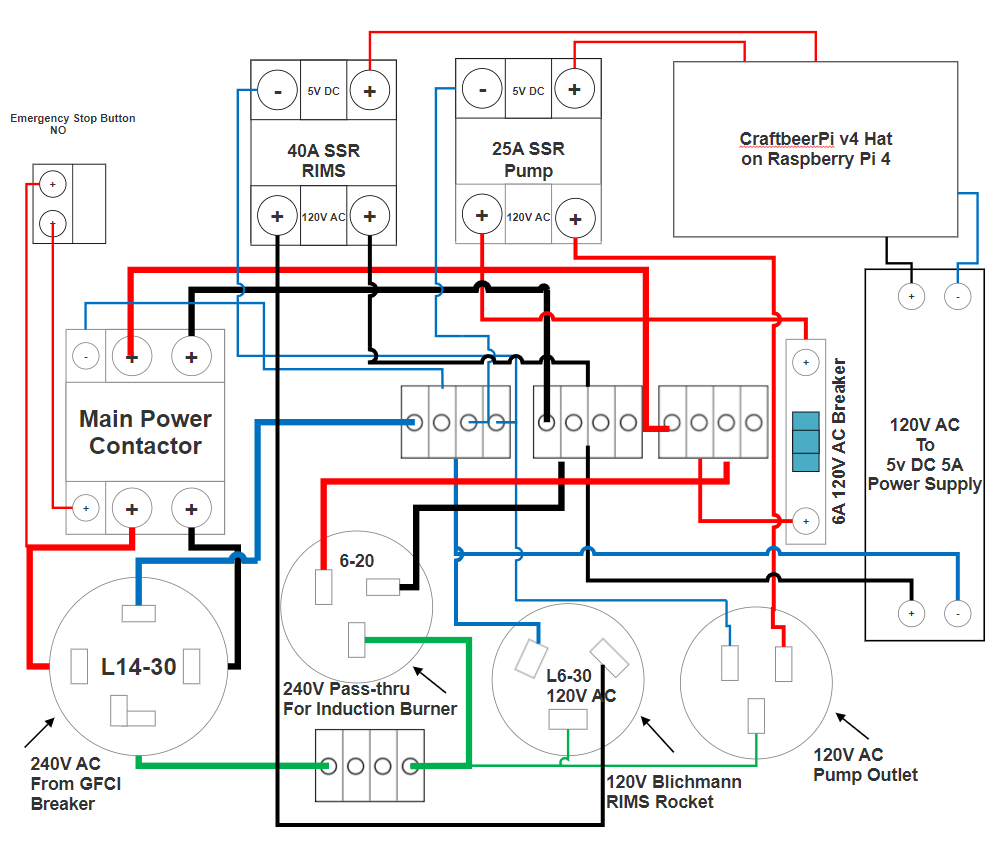
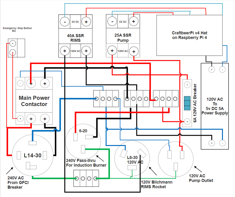
Background: I have an Avantco IC3500 induction burner I'm using for the boil side and a Blichmann RIMS Rocket for the mash. The circuit shown below is the goal layout with an eventual eye towards changing to a traditional electric element down the road. I have used the circuit before just powering the induction burner on its own and running the RIMs/Pi circuit off a separate 120v GFCI circuit.
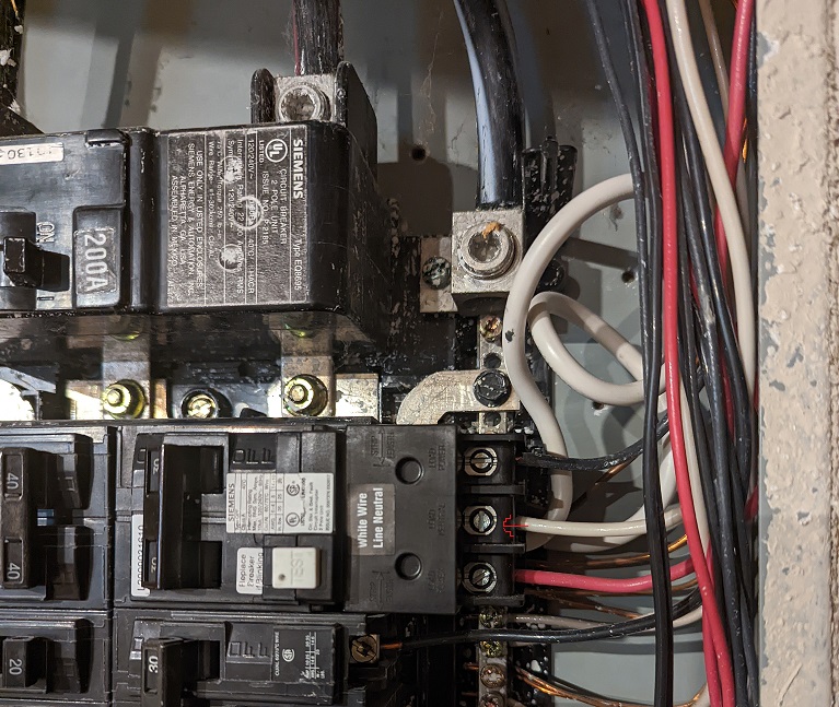
My issue as I stated above is that as soon as I plug in the circuit, the breaker trips. I've tried taking the circuit down to its very basic levels and have found that the breaker is happy if I direct wire the IC3500 alone and that the breaker will trip if I only use one leg of the 240v. For the one leg test, I wired up a 120v outlet and plugged in the pump I will be using. I've seen multiple controllers that take in 240v and have a 120v pump. What am I missing?


![Craft A Brew - Safale S-04 Dry Yeast - Fermentis - English Ale Dry Yeast - For English and American Ales and Hard Apple Ciders - Ingredients for Home Brewing - Beer Making Supplies - [1 Pack]](https://m.media-amazon.com/images/I/41fVGNh6JfL._SL500_.jpg)


