Totally building an electric biab system

Homebrew Talk - Beer, Wine, Mead, & Cider Brewing Discussion Forum

Help Support Homebrew Talk - Beer, Wine, Mead, & Cider Brewing Discussion Forum:

This site may earn a commission from merchant affiliate links, including eBay, Amazon, and others.
I like the one temperature probe idea. I am still contemplating modifying my setup to go that direction.

I also wish I knew about the solderless tri-clamp fitting at brew hardware, I would have used that for the element.

Looking good!
 
Nice build! Would you be able to post the parts list and your final wiring schematic? I would love to build something like this but very limited in wiring skill. Thanks!!!
 
Nice build! Would you be able to post the parts list and your final wiring schematic? I would love to build something like this but very limited in wiring skill. Thanks!!!

I don't have much in the way of a parts list but I kept the wiring diagrams in this thread up to date as things changed and they are currently exactly the way it is now wired.

One picture I forgot to add is the cleaned up wiring in the panel, just wrapped things up with zip ties as I had planned.

More importantly! I still have not brewed on the system yet! I have done a few strike water and boil temp timings but that is all so far. Life happened and our second kid arrived so that has been taking a "little" bit of my time. Hope to be brewing soon though.

zY9LGik.jpg
 
Nice build, So much has advanced in the e-Brewing field since I started my build 3 or 4 years ago.

1) I like the way you mounted you element with the TC. (I mounted mine Kal style with a outdoor box except its a single gang instead of double gang)

2) I love that Auber came out with the EZ Boil, If I was building a panel today I think I would use this over the PID

3) I like the simplicity of your design, I do have a few extra components like a Emergency Stop and DIN Mounted Contractors and DIN Mounted breakers

4) I like that you put an Elbow on the lid for re-circulation (I might have to borrow that Idea to remove strain from return line.

5) Your ripple Element appears to be totally stainless.

Can't wait to hear how you first brew session with it goes.
 
Well as with many of us, a bit of life happened and it was not until a few weeks ago that I could finally brew on the new setup.

Brewed up a session blonde ale, and it was probably my smoothest brew day ever.

Roughly 16 minutes to go from 63F to 150F to mash in, and another 16 minutes to take it from 150F to boiling. Couldn't be more pleased with those times.

Only a few minor things.

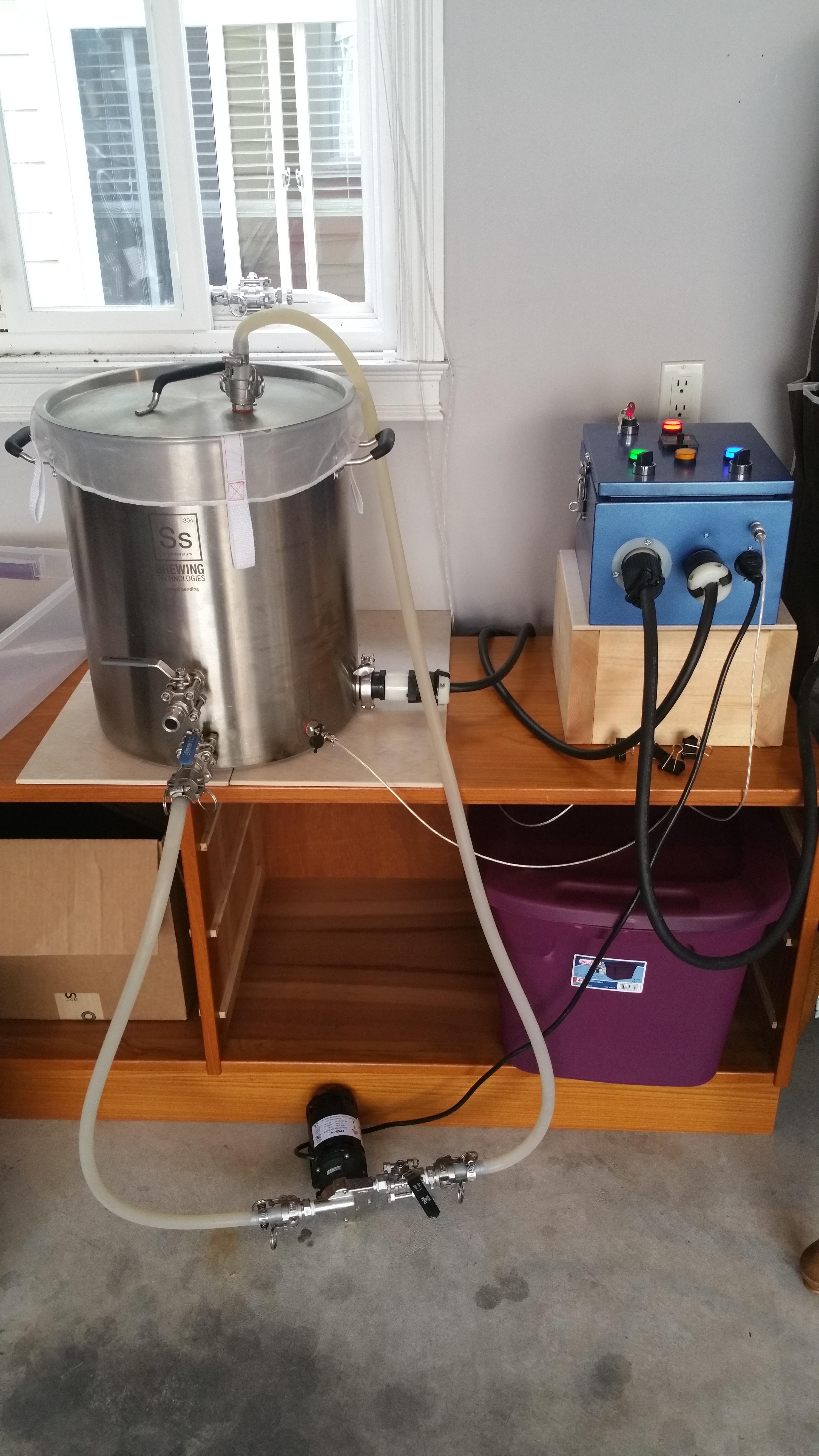
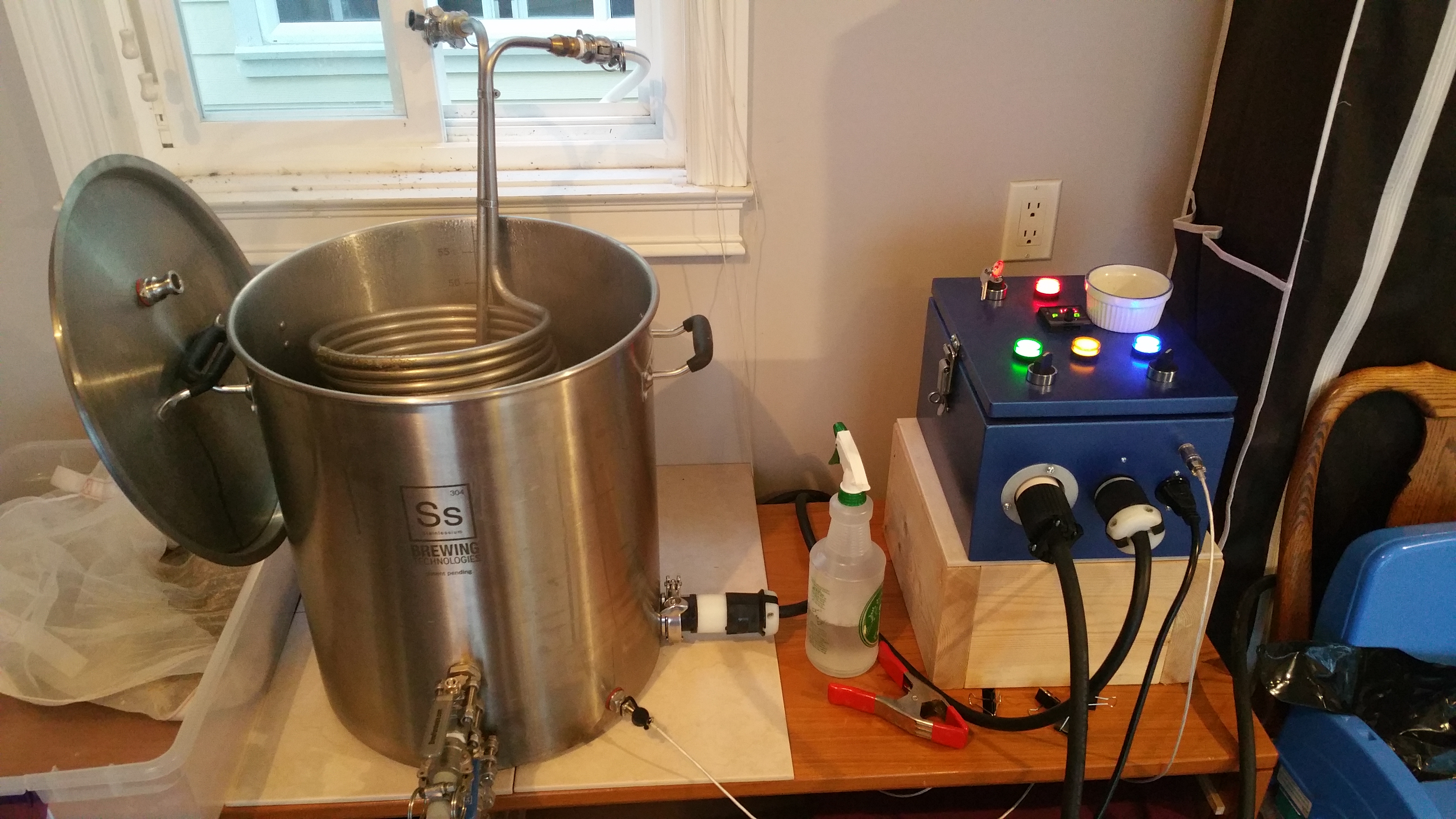
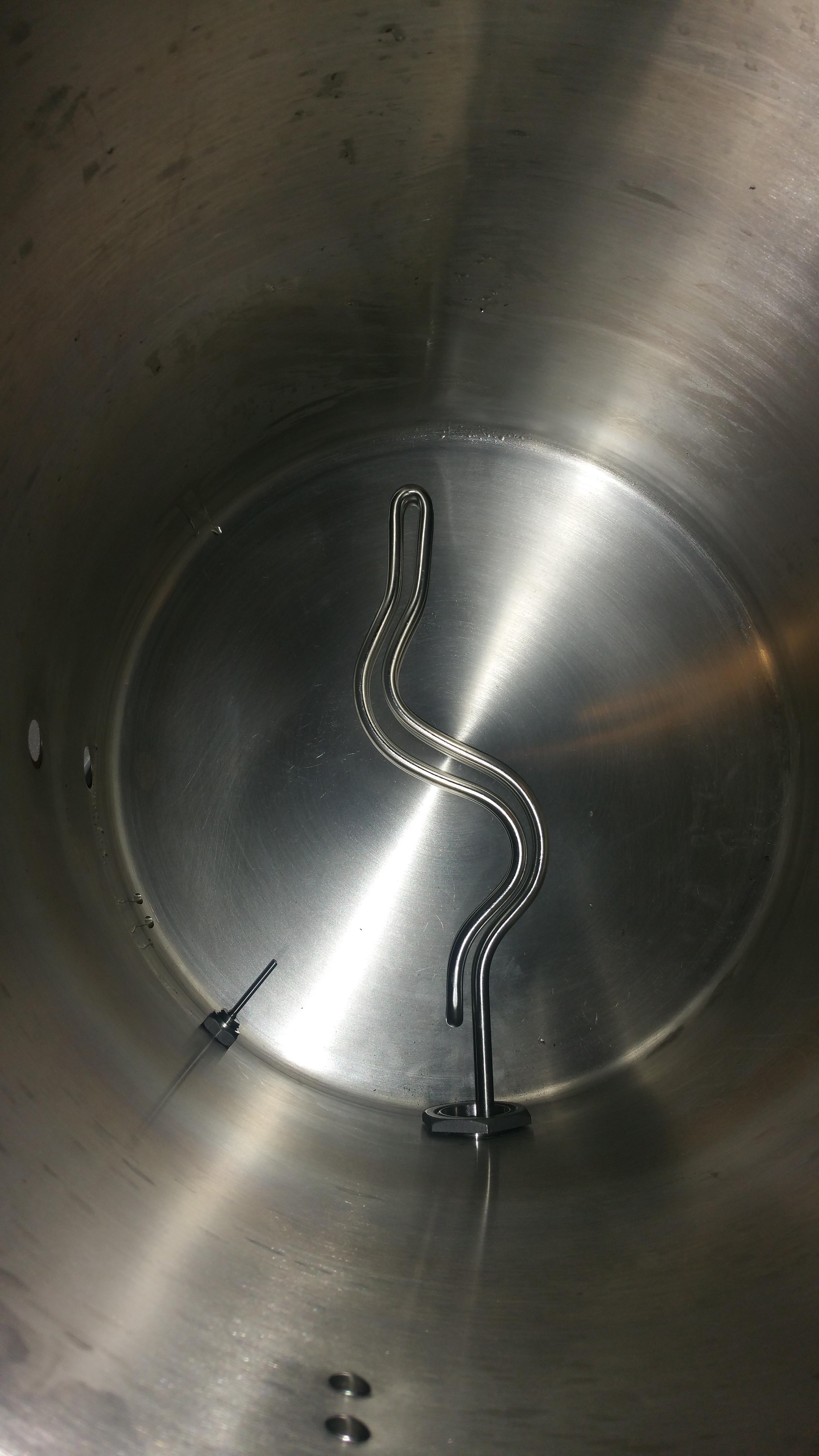
My immersion chiller is fairly tall since I originally got it for this 15 gallon kettle to do both 5 and 10 gallon batches. Now it doesn't sit on the bottom, actually I had it sitting on my false bottom so it's not on the element. Most of it is really out of the wort now, not sure how i'm going to deal with that but I am really considering moving to a counterflow chiller. Chilling time was not horrible but much slower than it was before when it could sit on the bottom.

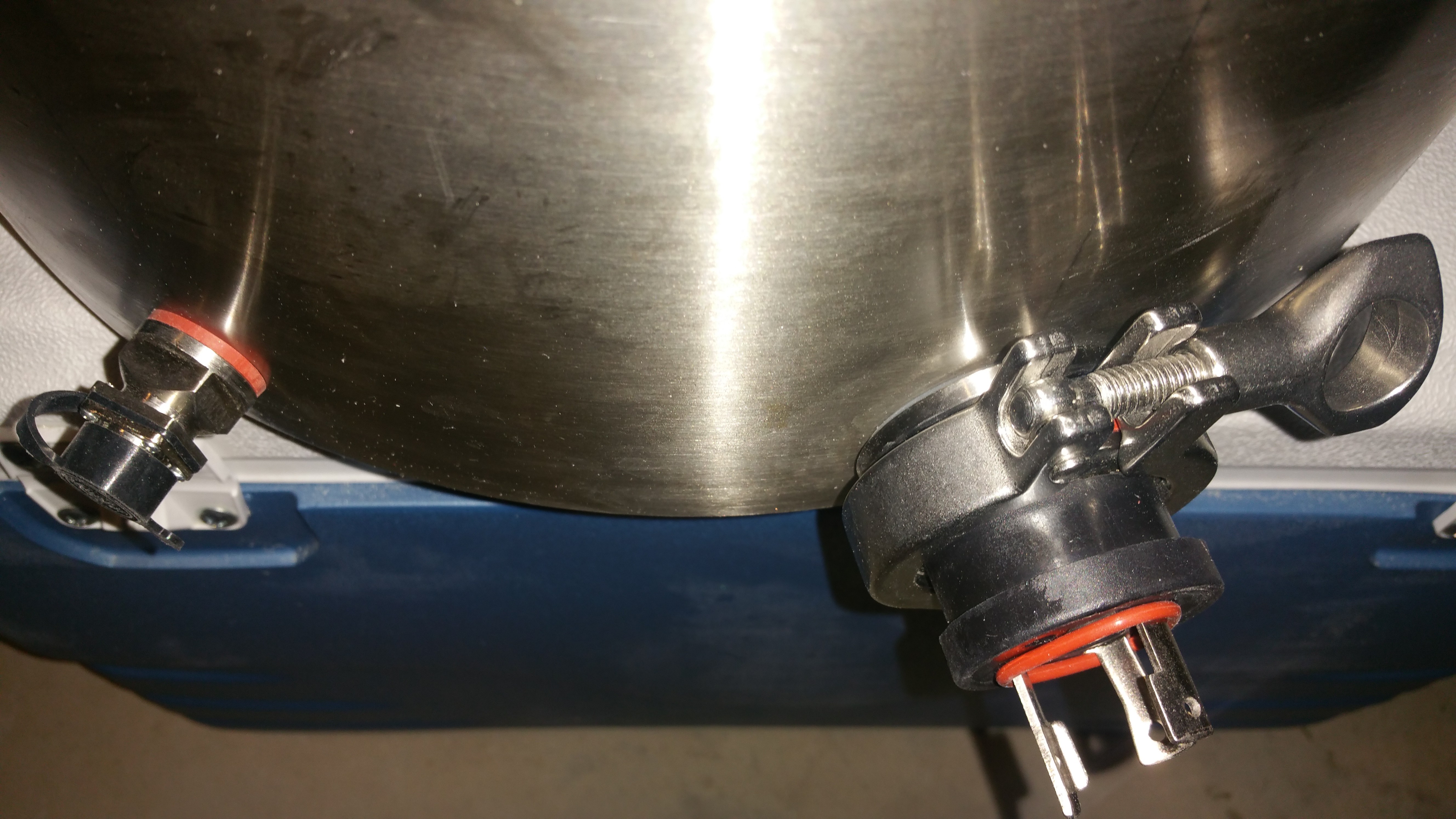
The elbow on my lid connection would not stop leaking so its a vertical connection for this brew, I have since remedied that and it connects at the proper angle again without the hose bending at an angle.

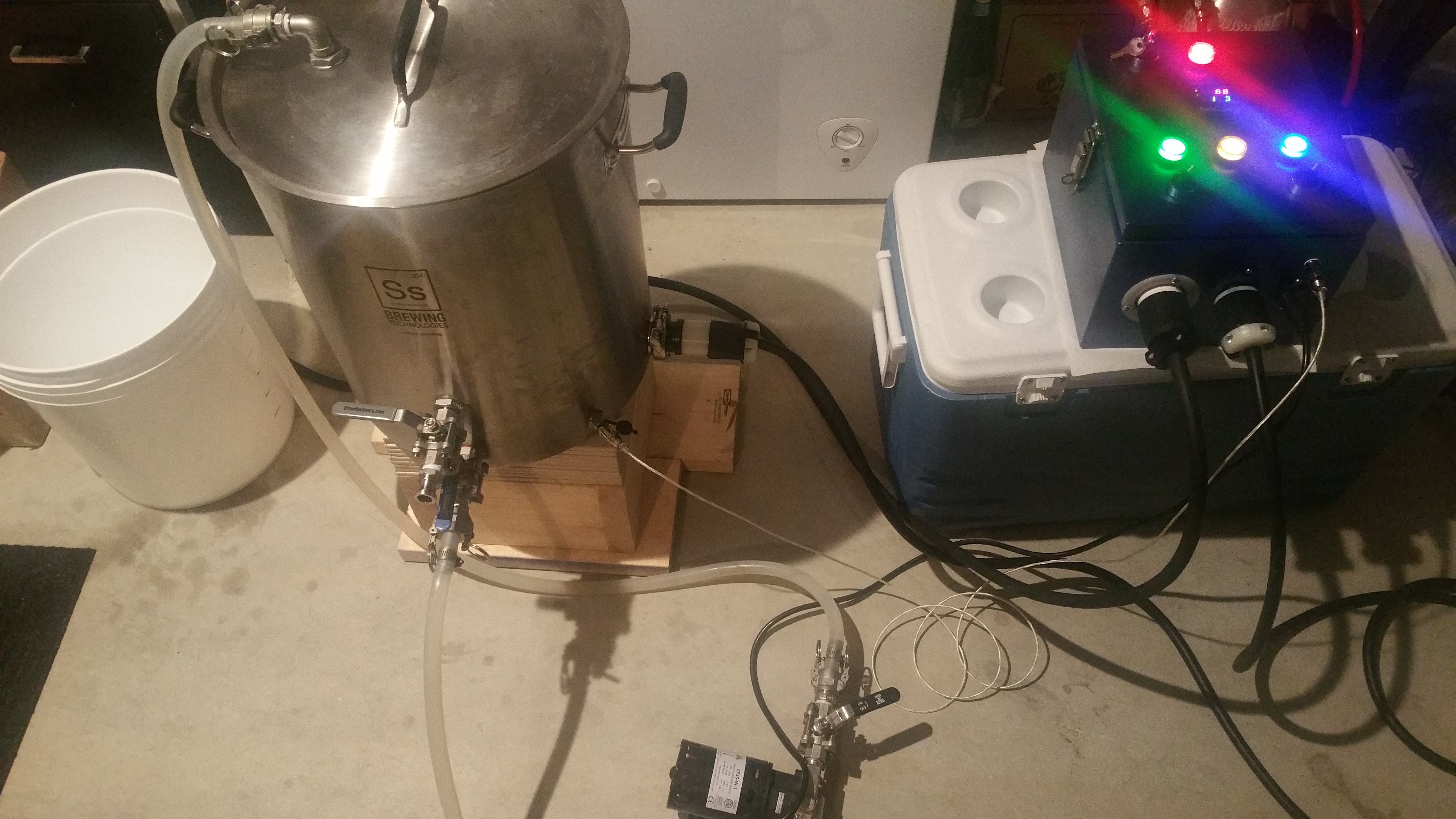
So happy to have gone electric!


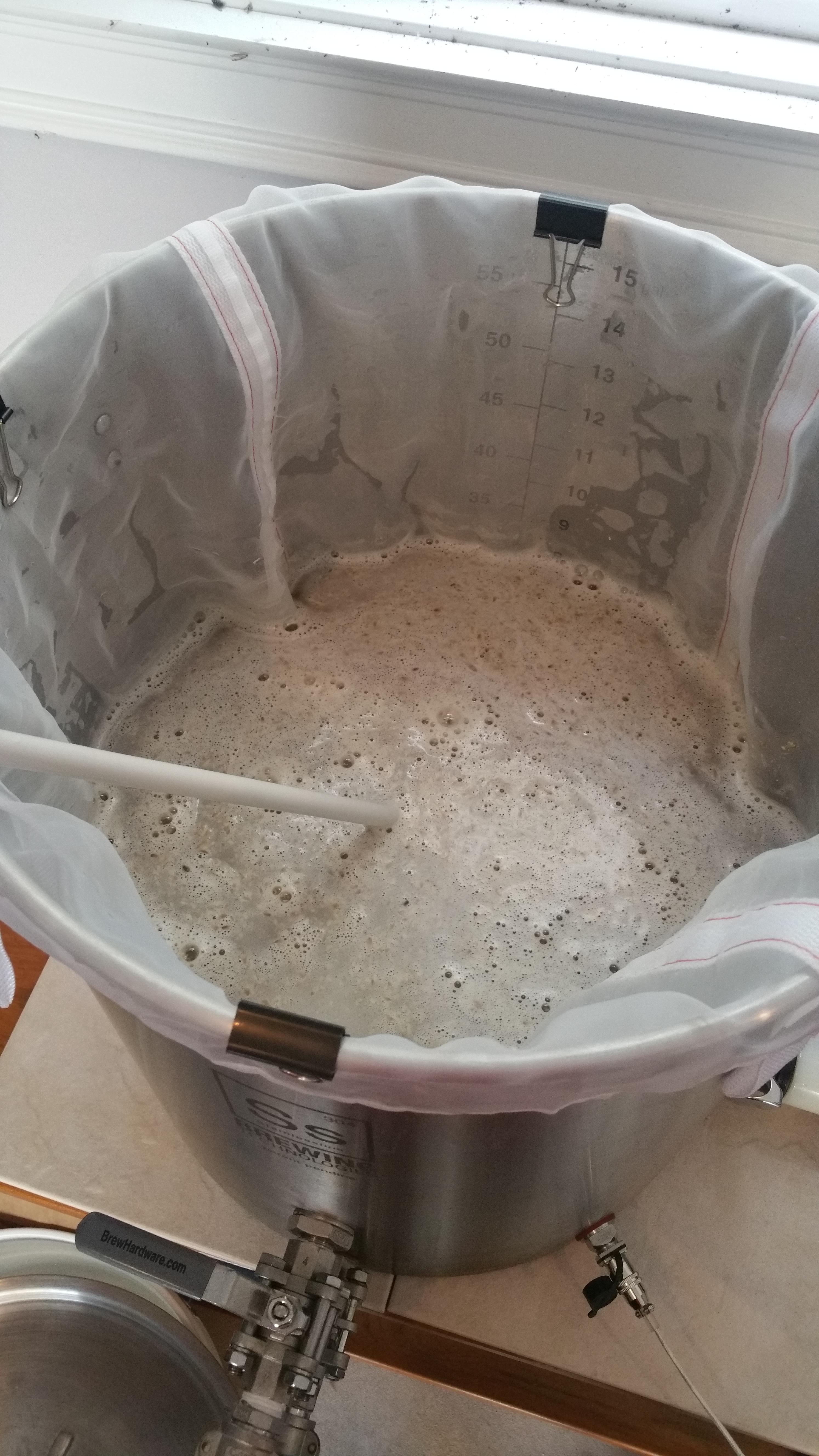
Just mashed in about to give a stir, put in the recirc attachment and close the lid.

SypyXXb.jpg


System is so compact yet super powerful, I am very happy with my brew days.

gLW569M.jpg


Boil complete, just threw the chiller in about to shut off the elements and start chilling.

iybaHj5.jpg
 
Looking great!

I personally remove my false bottom before the boil, and place the immersion chiller directly on the element. No issues for ~1.5 years now. Though my chiller is 25ft copper coil, so take that for what its worth.
 
Looking great!

I personally remove my false bottom before the boil, and place the immersion chiller directly on the element. No issues for ~1.5 years now. Though my chiller is 25ft copper coil, so take that for what its worth.

Thank you, I appreciate the comment. I just worry the weight of the 50ft stainless steel coil might be too much for the element or start torquing the weldless TC connection too much.

Either way I would like a shorter more condensed coil or maybe just think about a counterflow chiller. I have heard decent things about some of the counterflow chillers as far as time and not having the clogging issues that plate chillers have sometimes.

Not trying to start a chiller type war :) There are already enough of those here. Just thinking out loud about what I should do in my situation.
 
I ended up scrunching my 50' 1/2" copper immersion chiller down so that most of the coils were overlapped once or twice, that keeps most of it submerged, even when I only run 6g batches. If you were worried about the weight you could use stainless rods to make feet and attach them directly to the coil. I just set my heavy copper IC right on the element.

If I was buying again today I might go the counterflow route, mostly to let me keep the lid on during chilling/whirlpool. Since I already own the IC I have had a hard time justifying the new expense...
 
You could fairly easily make a copper IC that is customized for your 5gal batches, and keep your existing one for 10gal batches.

The designs that have a coil within a coil, or interleaved coils, might be the most appropriate, because more of the coil tubing can be down beneath the surface of the wort.
 
Another couple test fit shots.


O1YLbyO.jpg


cN1ArOJ.jpg
Could you please clarify how you attached the heating element. On one of the pictures above to looks like its a TC element, but later there is a nut. Did you use a weldless kit and if so how badly it deforms the pot when tightened? Thanks!
 
You are correct, that is the exact fitting that I used from brewhardware. I have taken it off once or twice since installing it and I have not noticed any deforming of the pot at all. I would think you would have to crank it down pretty tight to deform the pot. It seals great and was the perfect solution for my build.
 
I know you’re build has been done for a while now but I have been building mine for a few months now and have a question on your wiring schematic. Maybe it’s a question
I wanted to fully understand the schematic before ordering parts and starting to wire it up, after looking over the great schematics from @doug293cz I decided to redraw the one that fit the closest in an effort to better understand it as well as have a modifiable version in case I wanted changes. The most obvious being the DSPR120, and marking the exact parts I would be using.

I drew it using Gliffy Diagrams if anyone is interested, its a Chome App.
Gliffy Diagrams

r9qPSVh.jpg

I know you’re build has been done for a while now but I have been building mine for a few months and have a question on your wiring schematic. Maybe it’s a question for @doug293cz?
These LED indicator lights. Is there a specific reason you have the 220v one? In my mind you could wire it with 110 from the active side of the SSR to know it’s firing. Unless there is more information you get from having it wired with 220...🤔
 
I know you’re build has been done for a while now but I have been building mine for a few months now and have a question on your wiring schematic. Maybe it’s a question


I know you’re build has been done for a while now but I have been building mine for a few months and have a question on your wiring schematic. Maybe it’s a question for @doug293cz?
These LED indicator lights. Is there a specific reason you have the 220v one? In my mind you could wire it with 110 from the active side of the SSR to know it’s firing. Unless there is more information you get from having it wired with 220...🤔

I think the reason to use 220V is so if the SSR or contactor is stuck closed you have a good indicator of that.
 
I don't have much in the way of a parts list but I kept the wiring diagrams in this thread up to date as things changed and they are currently exactly the way it is now wired.

One picture I forgot to add is the cleaned up wiring in the panel, just wrapped things up with zip ties as I had planned.

More importantly! I still have not brewed on the system yet! I have done a few strike water and boil temp timings but that is all so far. Life happened and our second kid arrived so that has been taking a "little" bit of my time. Hope to be brewing soon though.

zY9LGik.jpg

Is it just me or are the two contactors shown in the bottom of the picture (on the orange pad) wired in series? No matter what path I follow, one of the two conctactors follows the other in series.

Maybe one is used for a safety lockout?
 
I know you’re build has been done for a while now but I have been building mine for a few months now and have a question on your wiring schematic. Maybe it’s a question


I know you’re build has been done for a while now but I have been building mine for a few months and have a question on your wiring schematic. Maybe it’s a question for @doug293cz?
These LED indicator lights. Is there a specific reason you have the 220v one? In my mind you could wire it with 110 from the active side of the SSR to know it’s firing. Unless there is more information you get from having it wired with 220...🤔
A 120V LED indicator wired from the load side of the SSR to neutral will always be on. This is because when the SSR is off, the LED is connected in series with the element to the other hot line. The element is a low value resistor, and the LED has a high impedance, so the voltage drop will mostly be across the LED, turning it on.

Brew on :mug:
 
Is it just me or are the two contactors shown in the bottom of the picture (on the orange pad) wired in series? No matter what path I follow, one of the two conctactors follows the other in series.

Maybe one is used for a safety lockout?
Yes the contactors are in series to the SSR and element, but the power for the pump and EZBoil does not go thru the second (element enable) contactor. The first contactor (closest to the power input) is the main power contactor, which controls all power to the panel, not just the element.

Using a contactor for the main power control does allow a safe start interlock to be implemented, although the design in this thread does not do that. The safe start interlock prevents the main power from being turned on if either the pump or element enable switch is on. So, you would have the pump or element come on unexpectedly when turning on the main power.

Here's a design very similar to OP's that implements the safe start interlock:

DSPR300 1-Pump 1-Element 240V rev-2.PNG


Brew on :mug:
 
Back
Top