Totally building an electric biab system

Homebrew Talk - Beer, Wine, Mead, & Cider Brewing Discussion Forum

Help Support Homebrew Talk - Beer, Wine, Mead, & Cider Brewing Discussion Forum:

This site may earn a commission from merchant affiliate links, including eBay, Amazon, and others.

Totally

Well-Known Member
Joined
Feb 11, 2016
Messages
249
Reaction score
86
Location
Vancouver
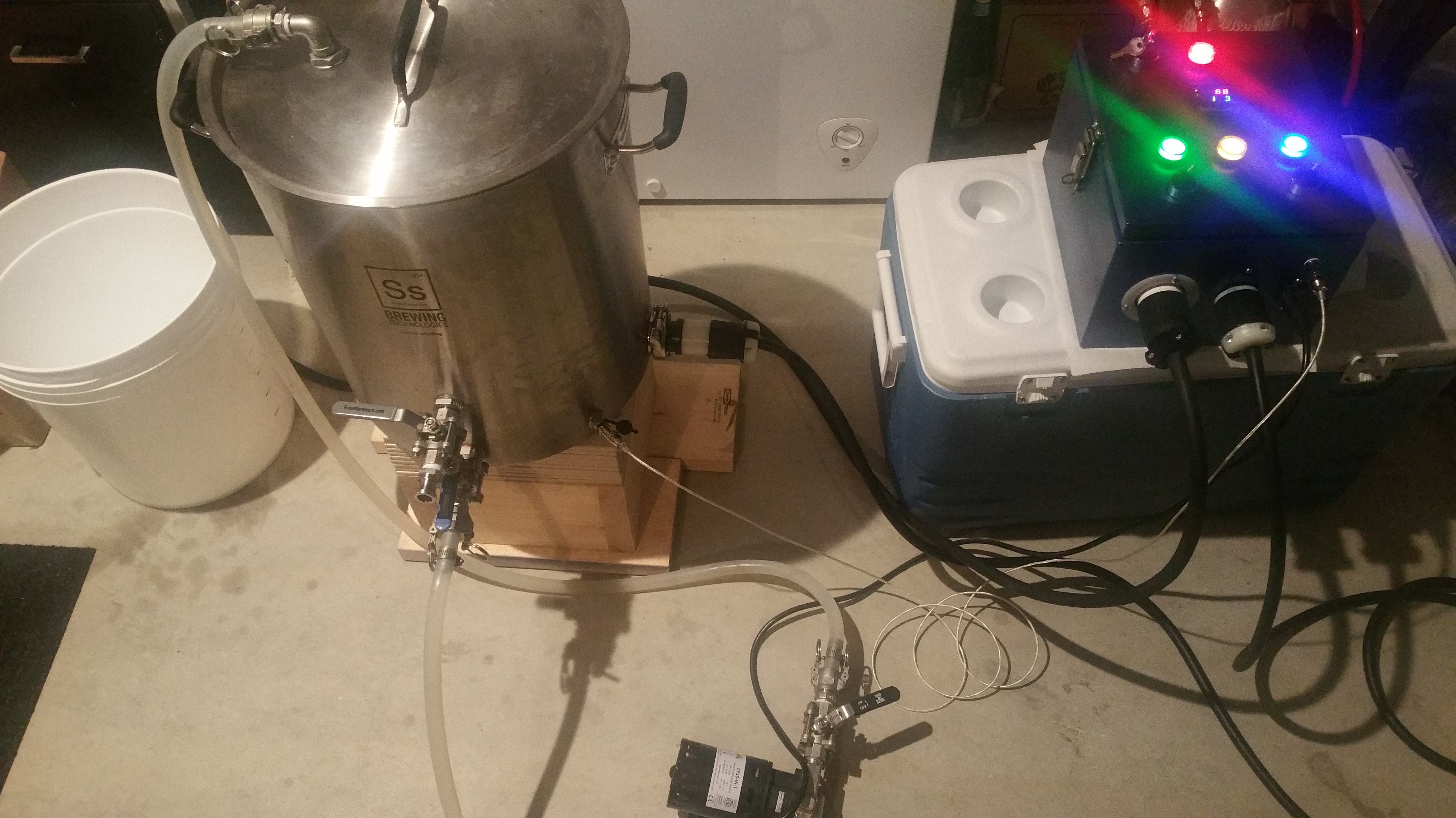
Finally it is happening.

I had started thinking about electric some time ago and first started a thread about trying to build it using a bottom drain keggle.

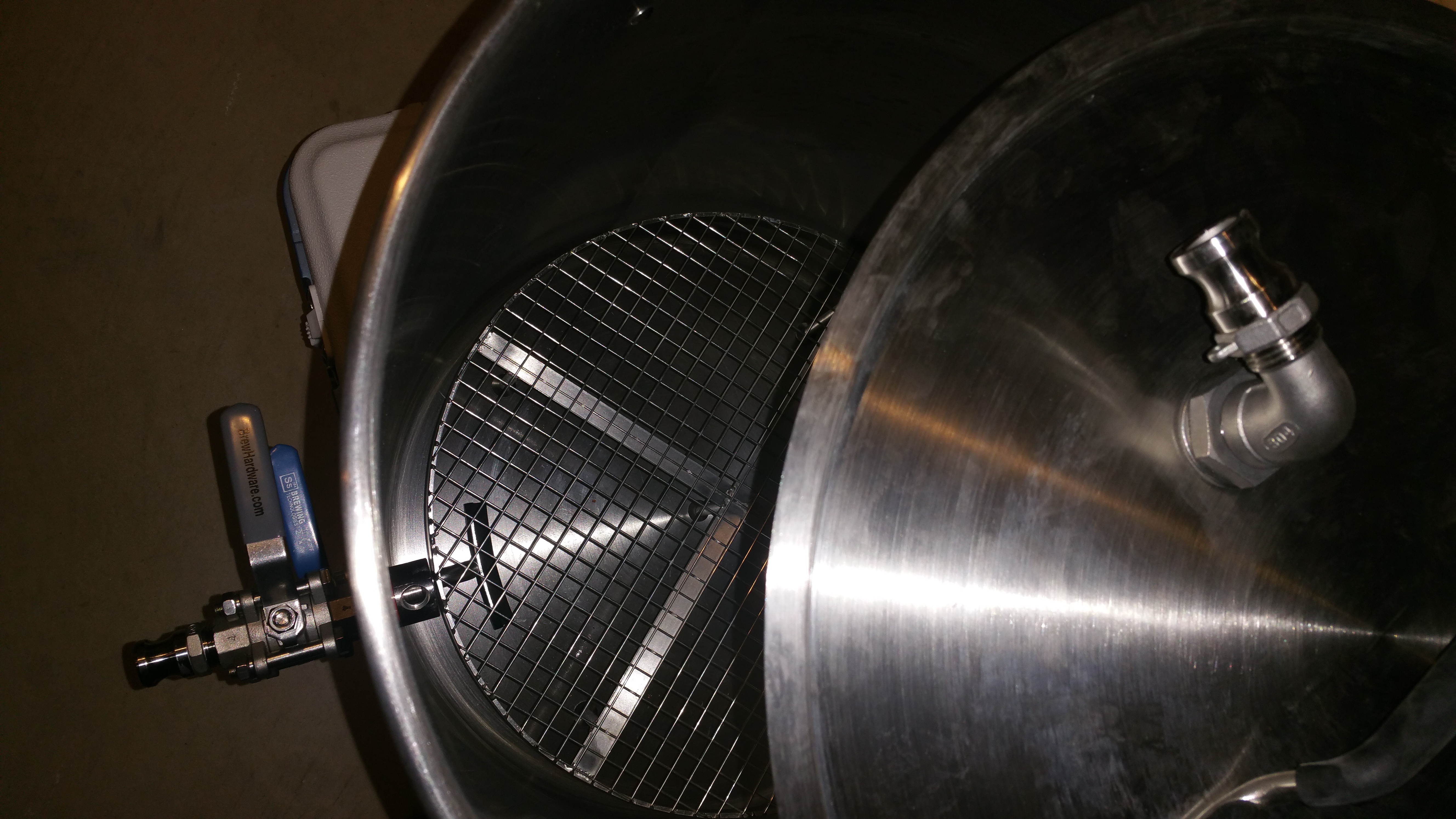
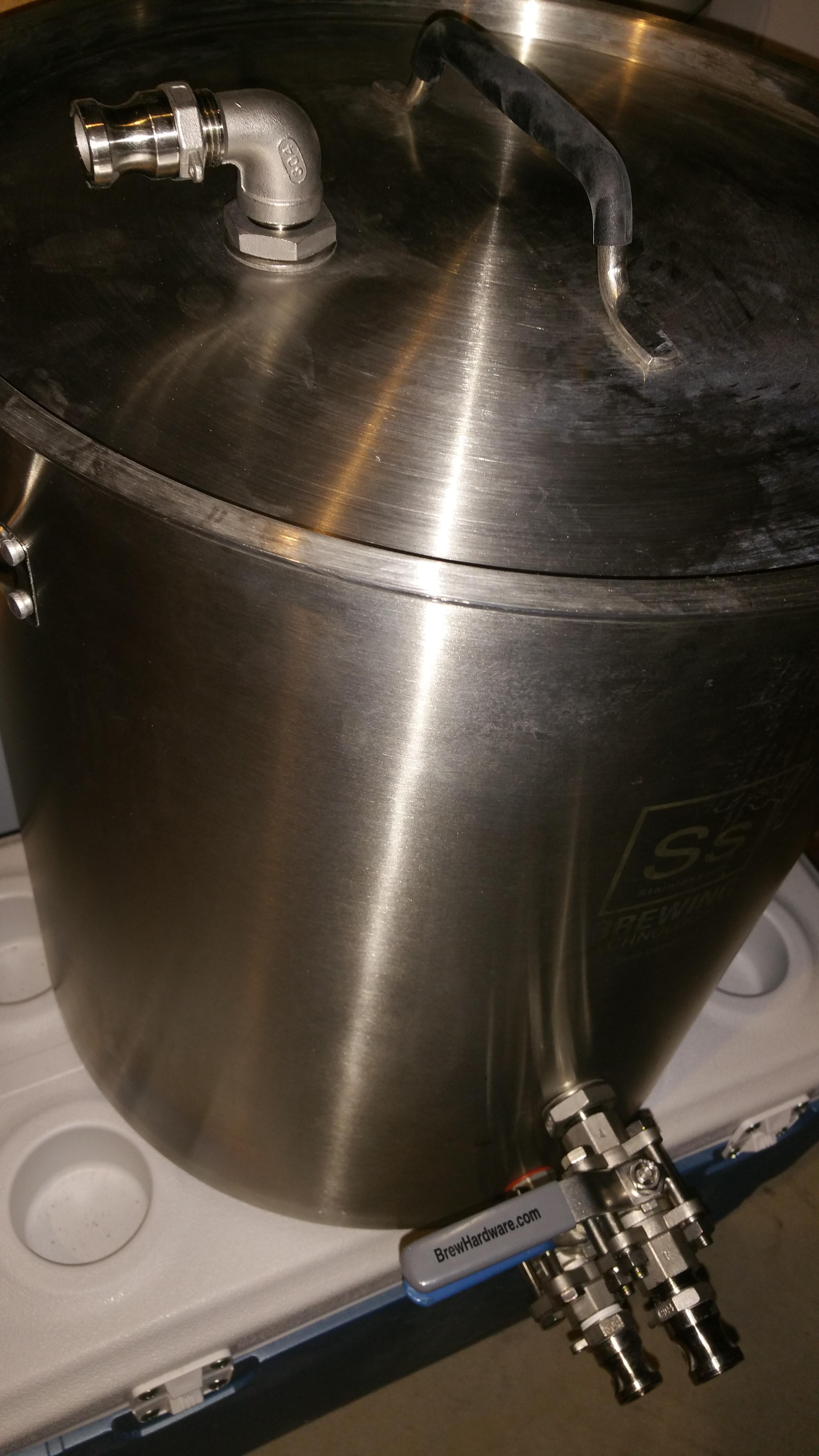
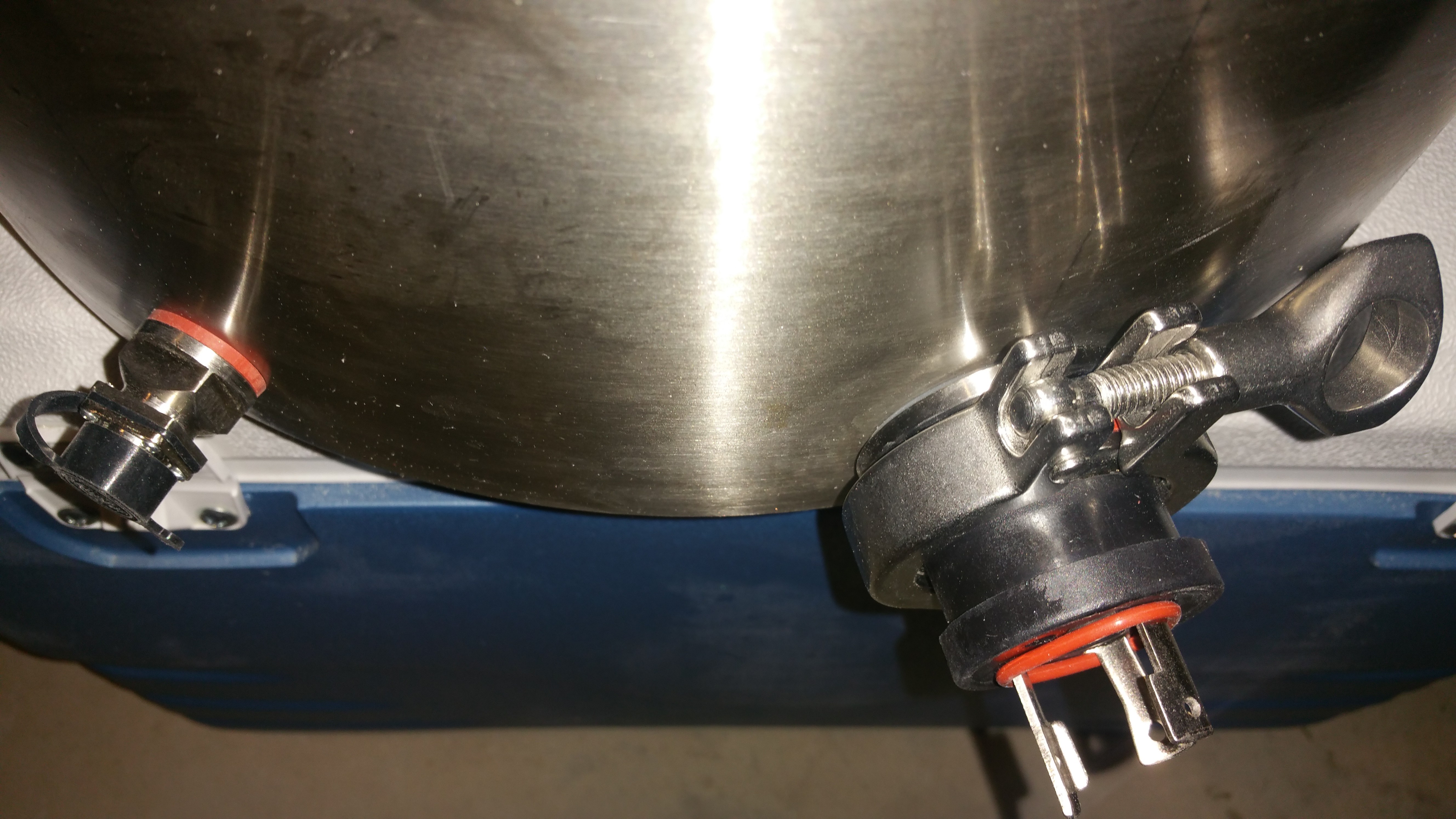
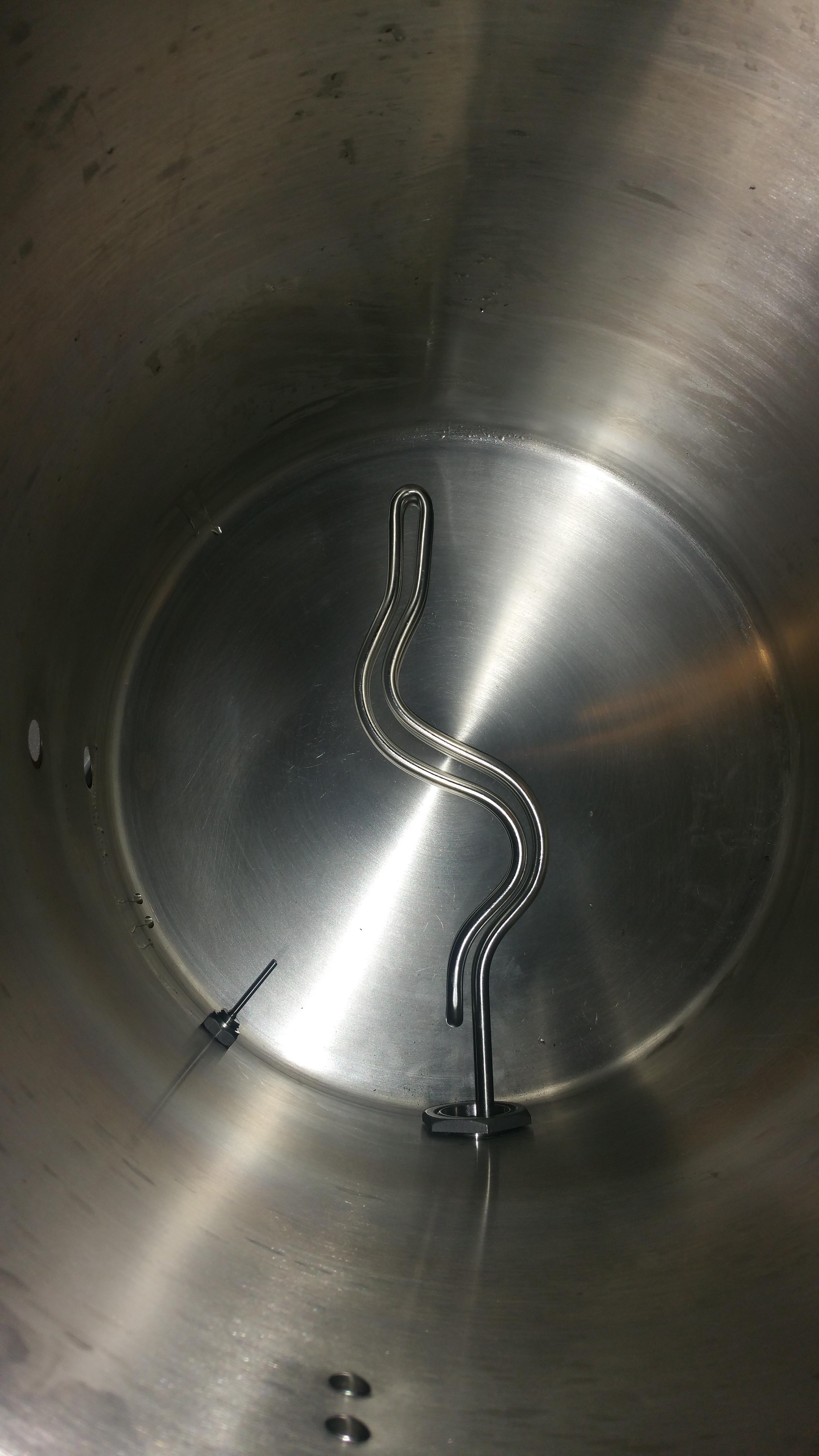
The more I got into the design I realized I should just drill my beautiful 15gallon ss brewtech pot and forget the keggle. Partially due to a great thread from @tofuguy here:
https://www.homebrewtalk.com/showthread.php?t=621165

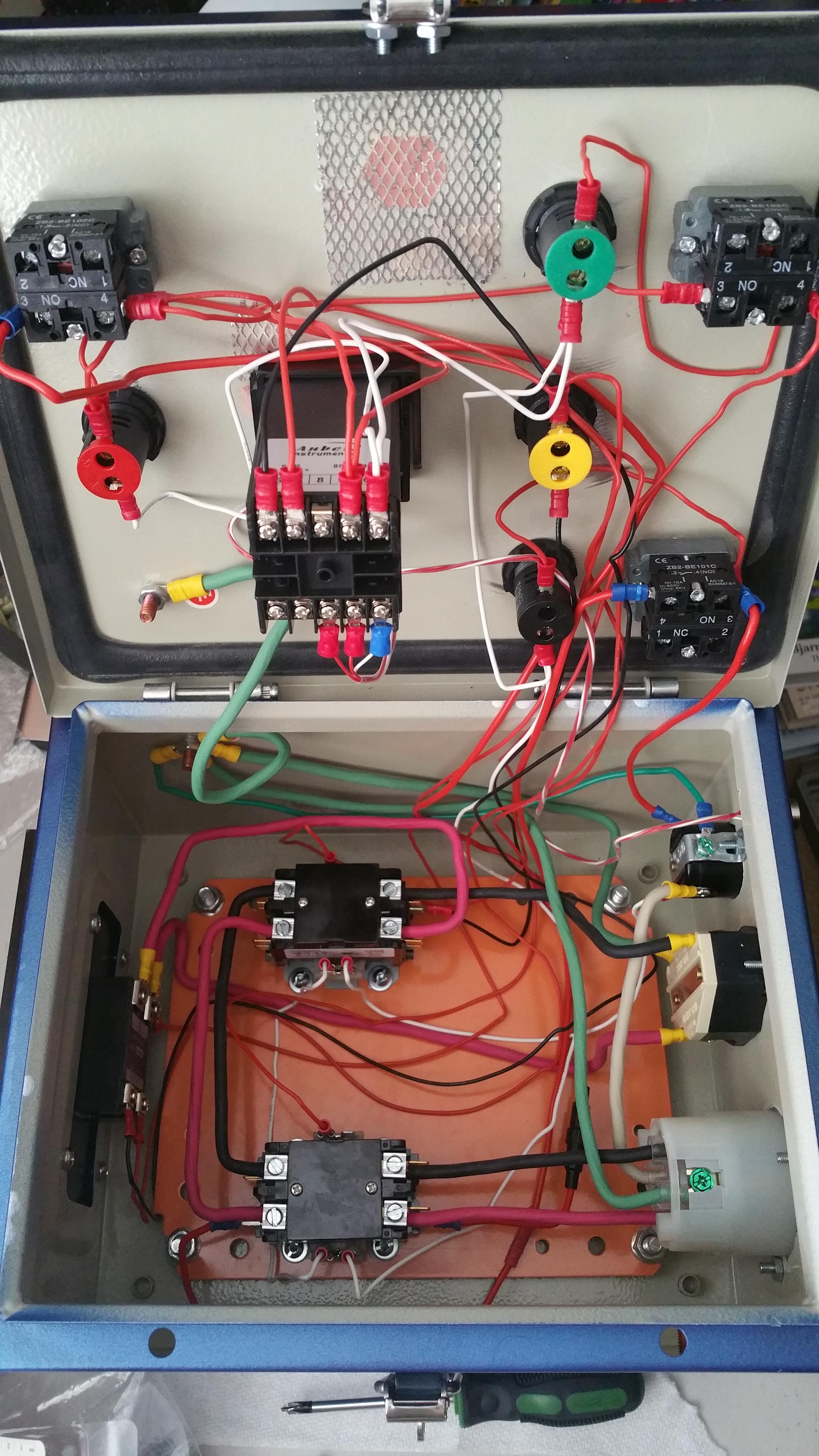
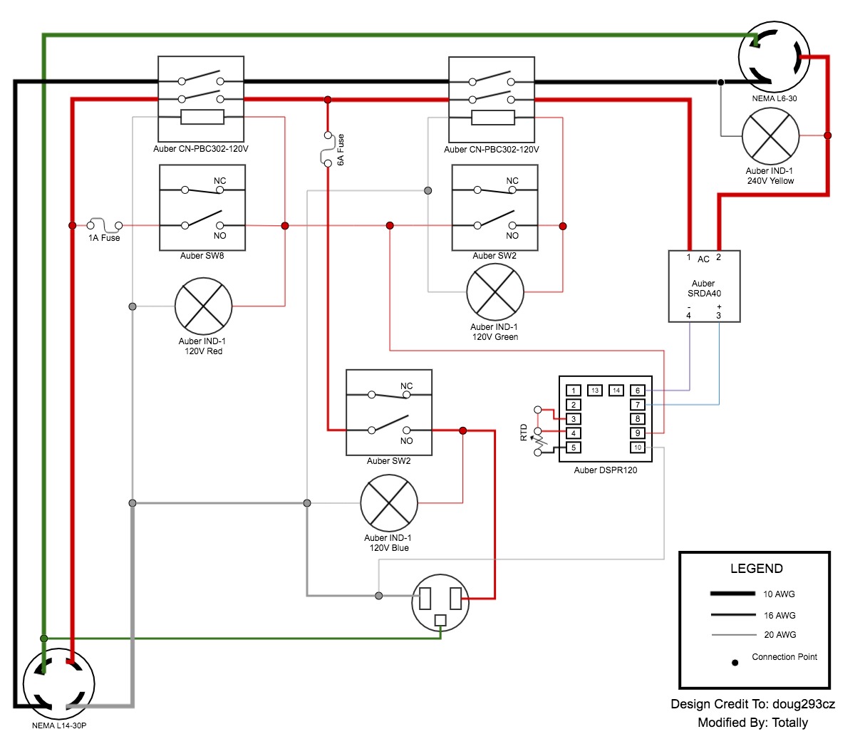
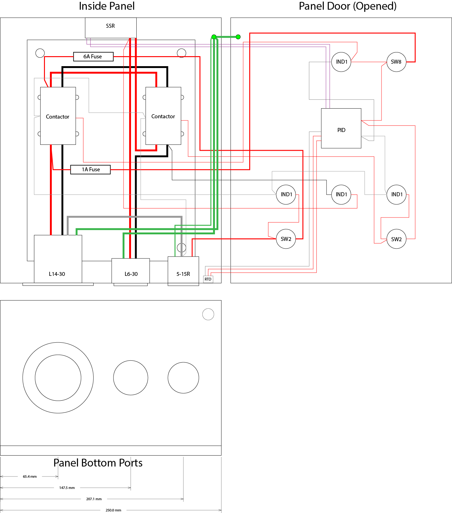
I had some great help from @doug293cz in my original thread about panel schematics as one would expect.

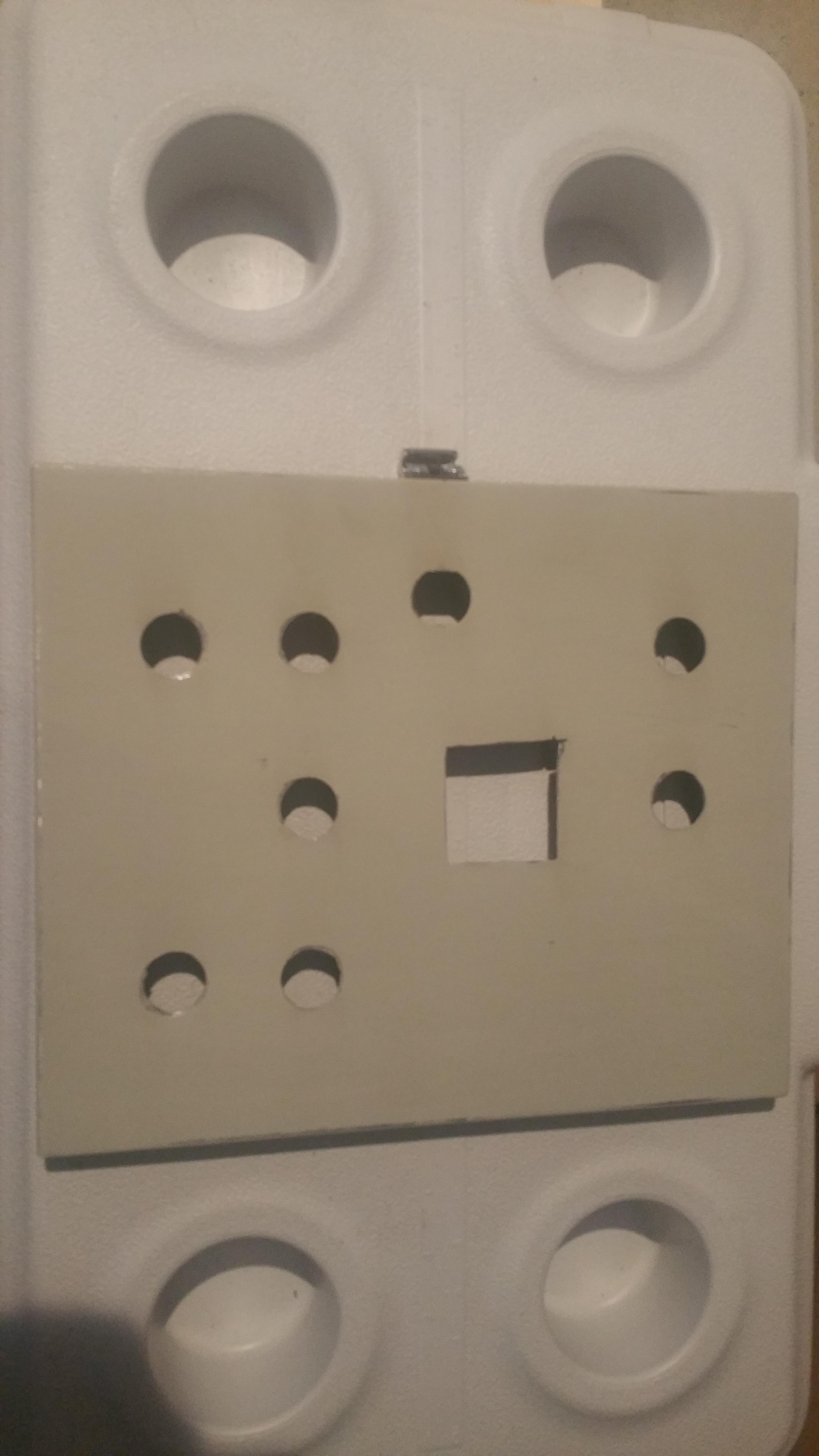
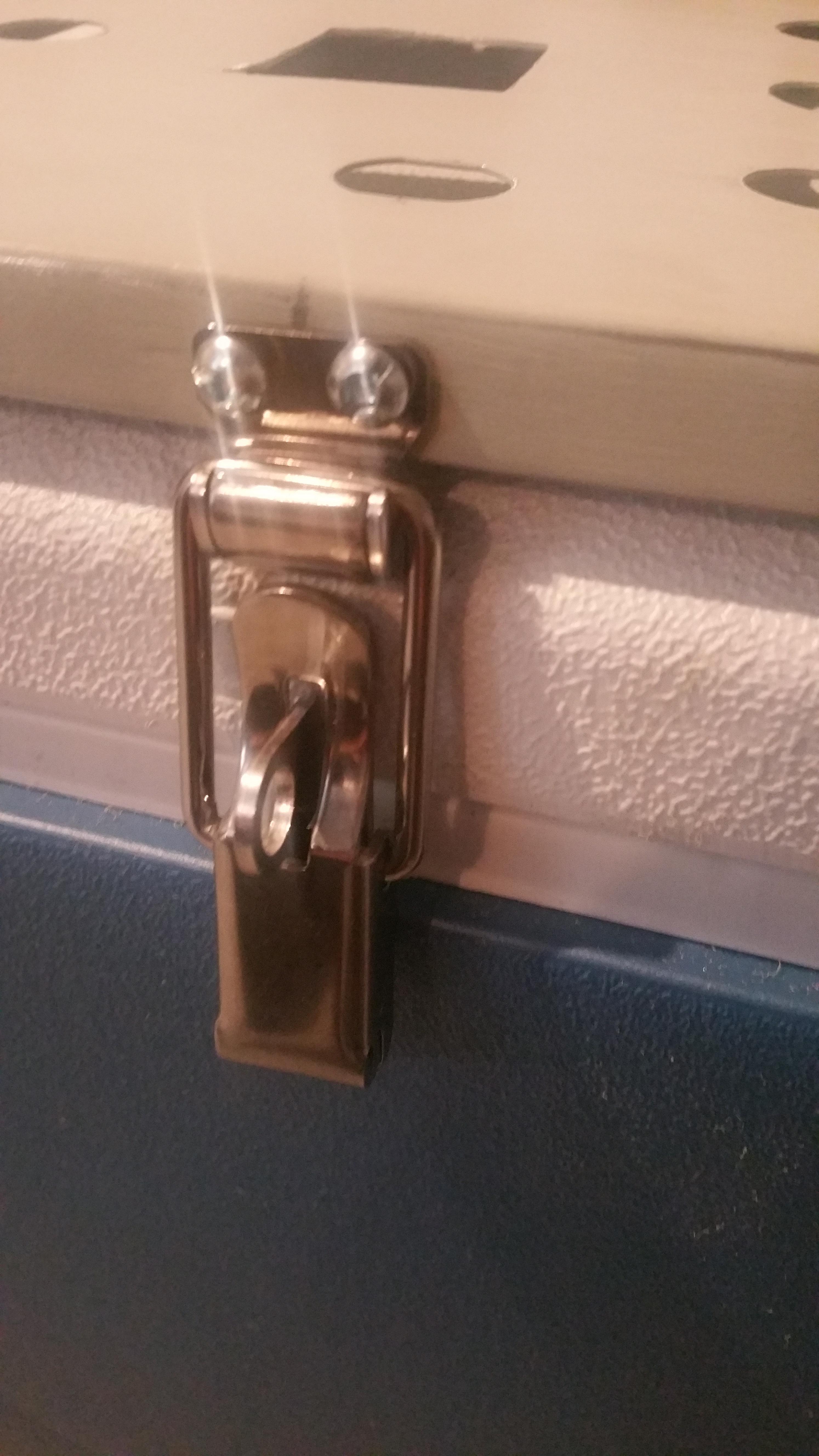
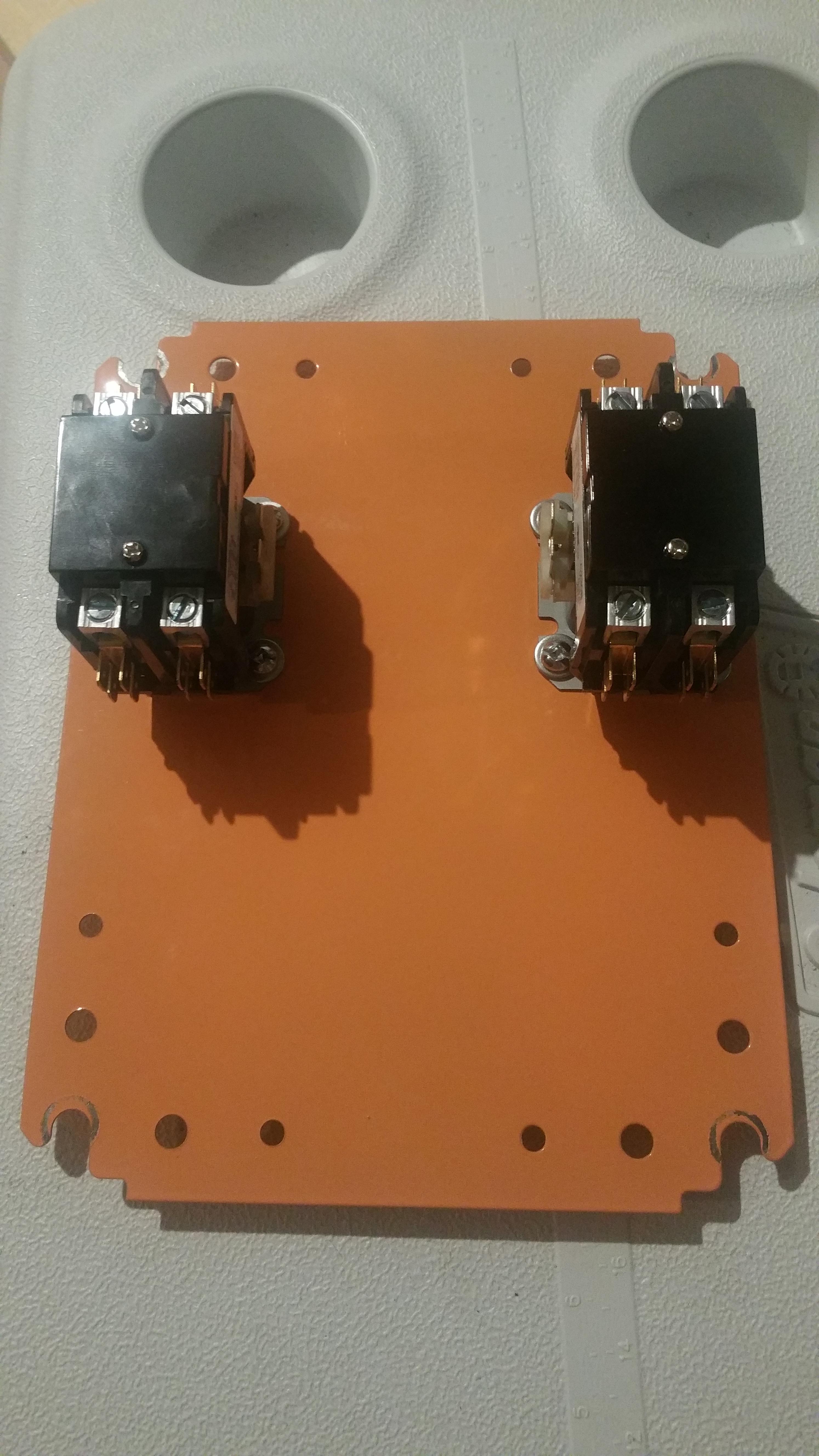
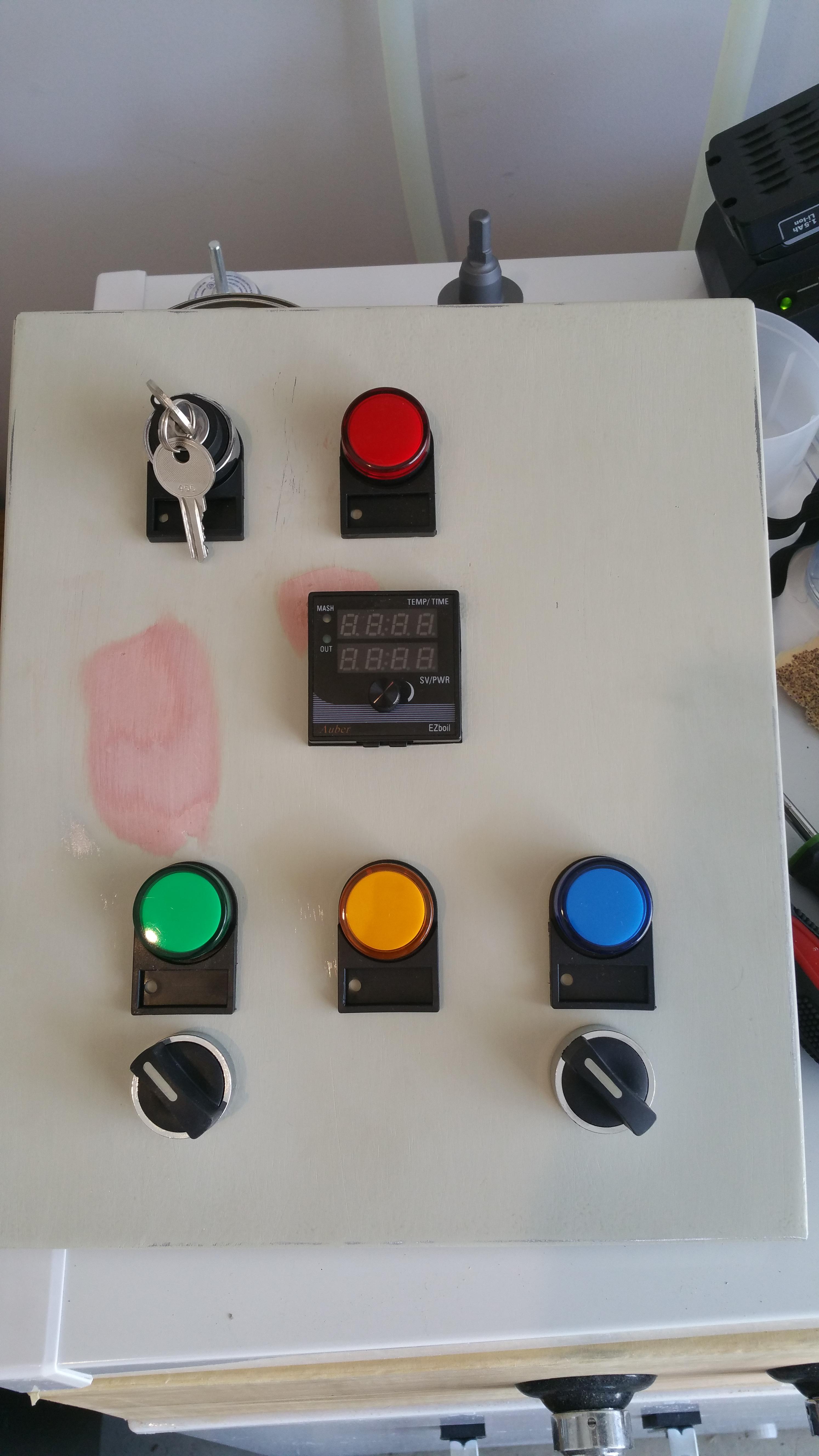
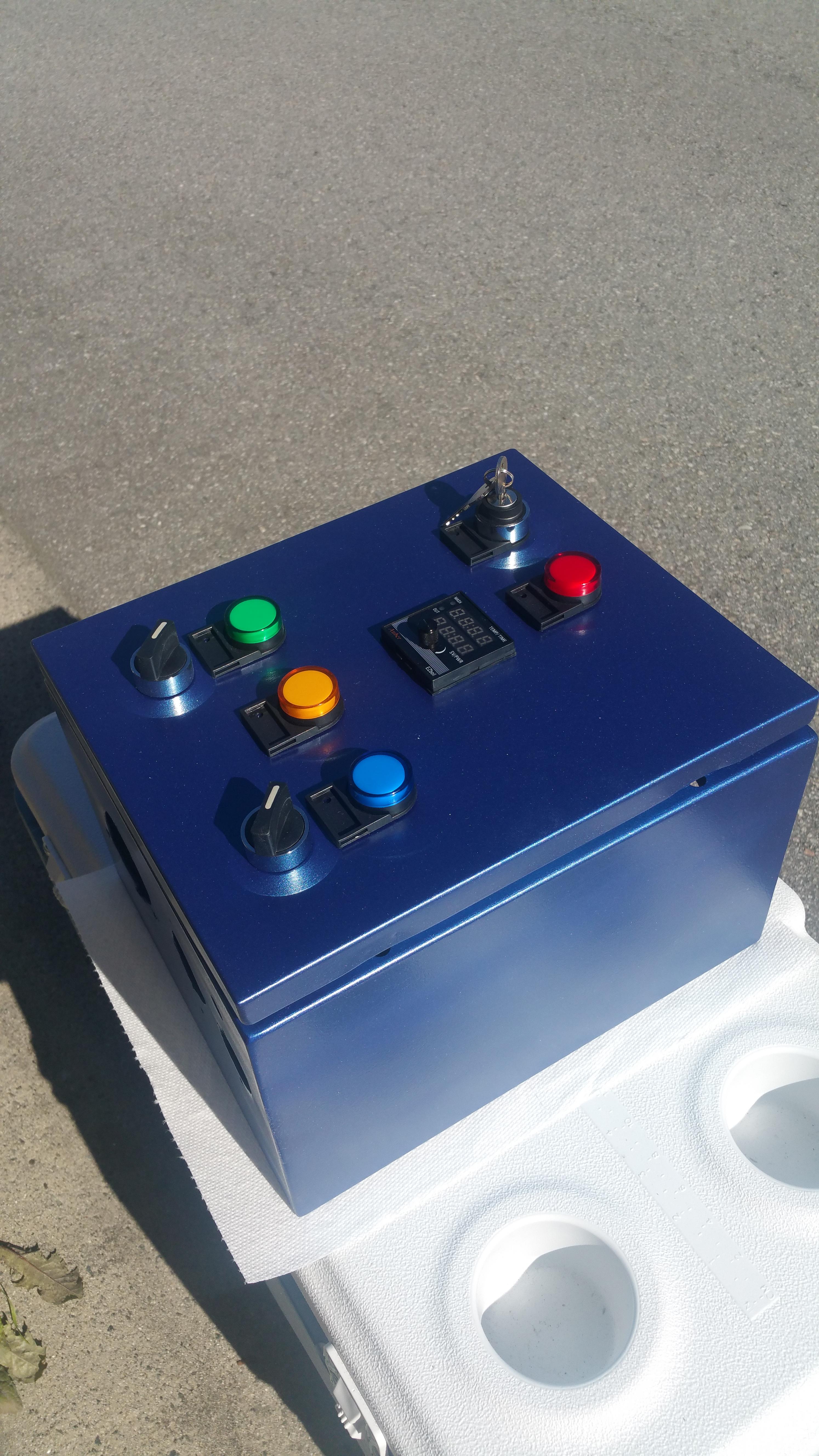
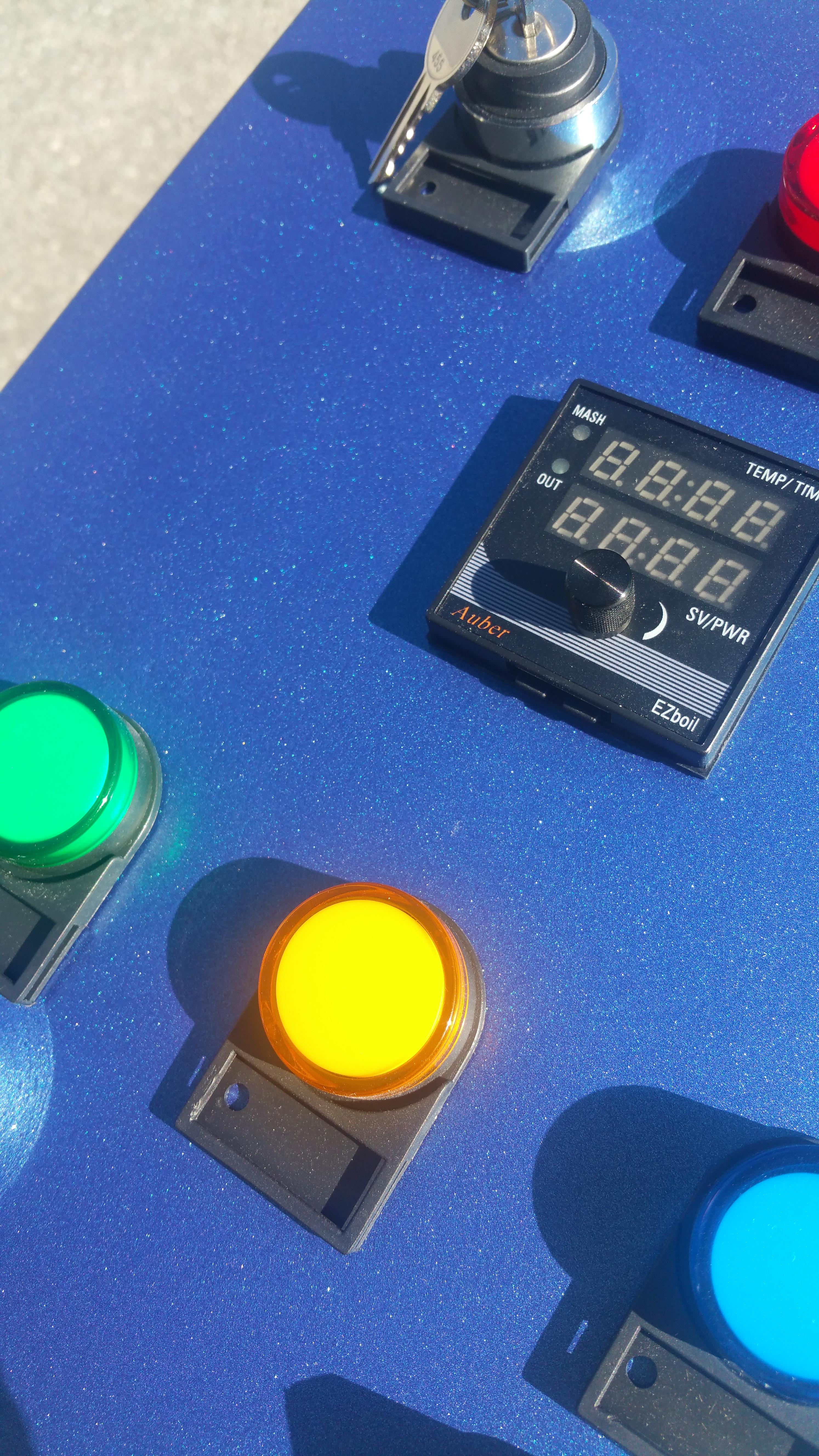
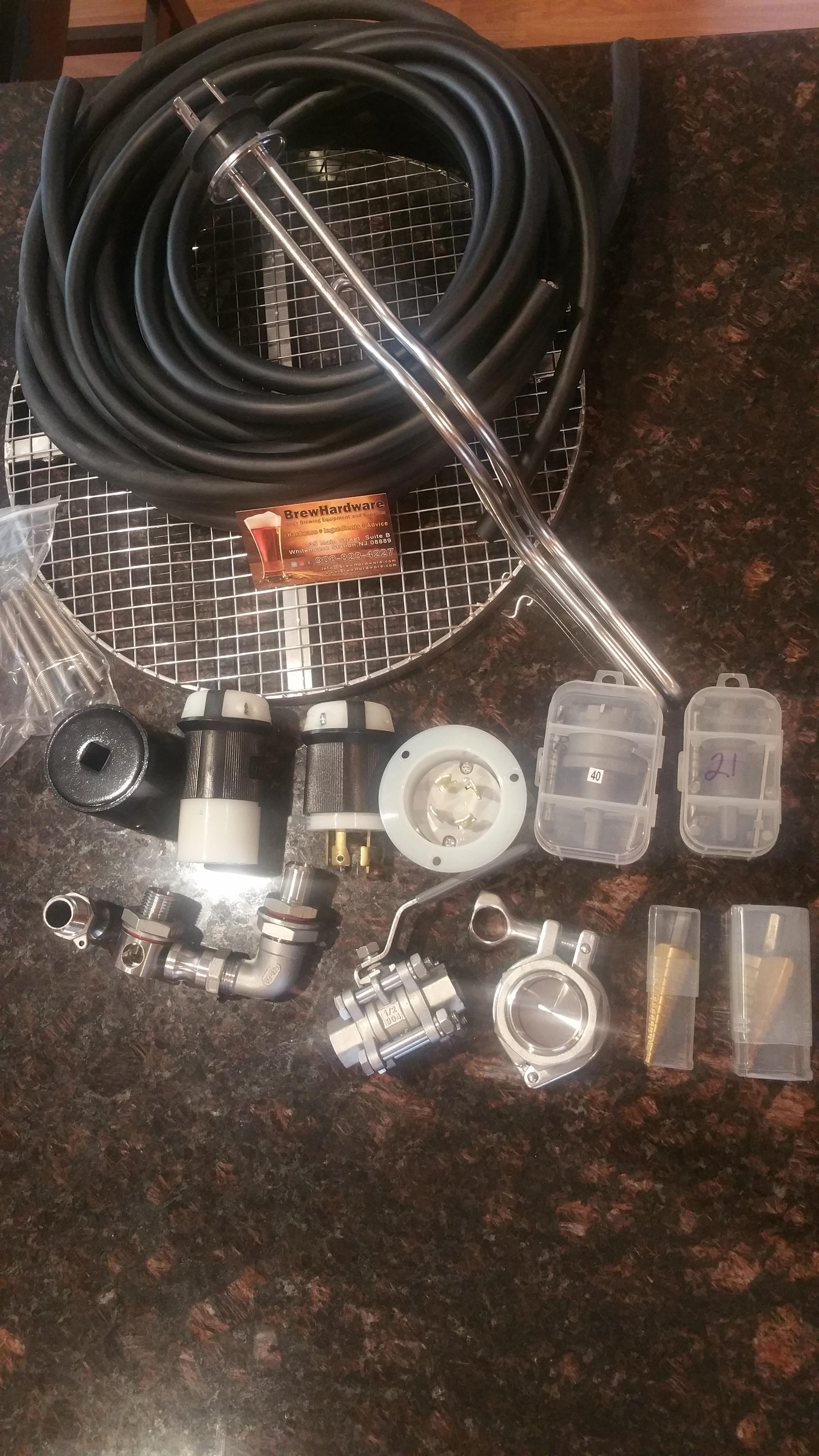
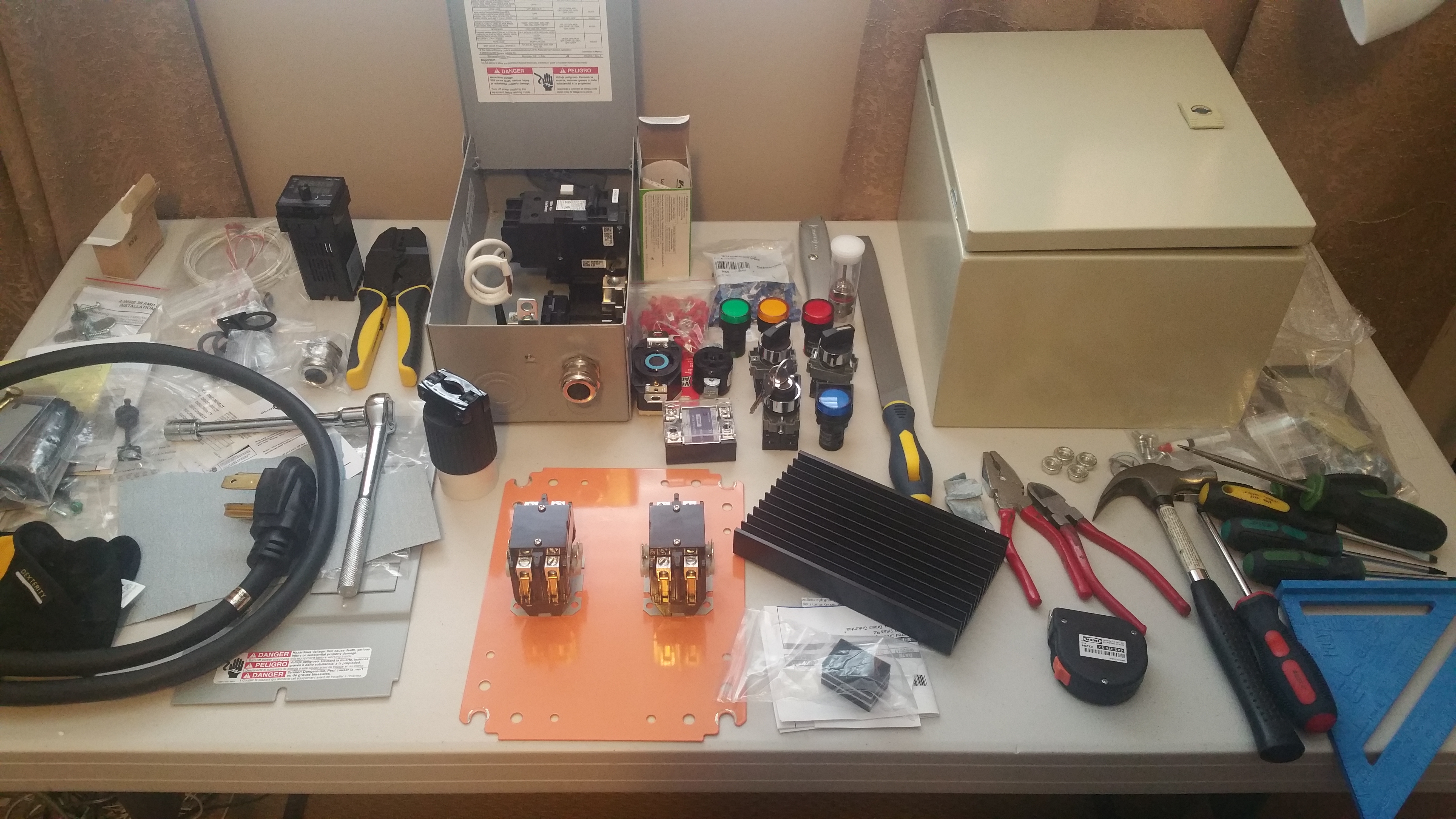
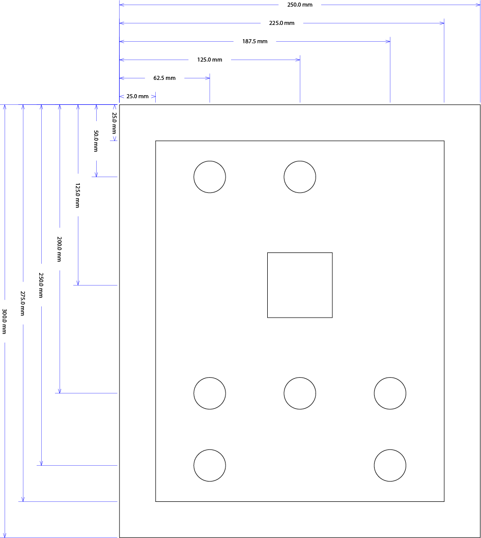
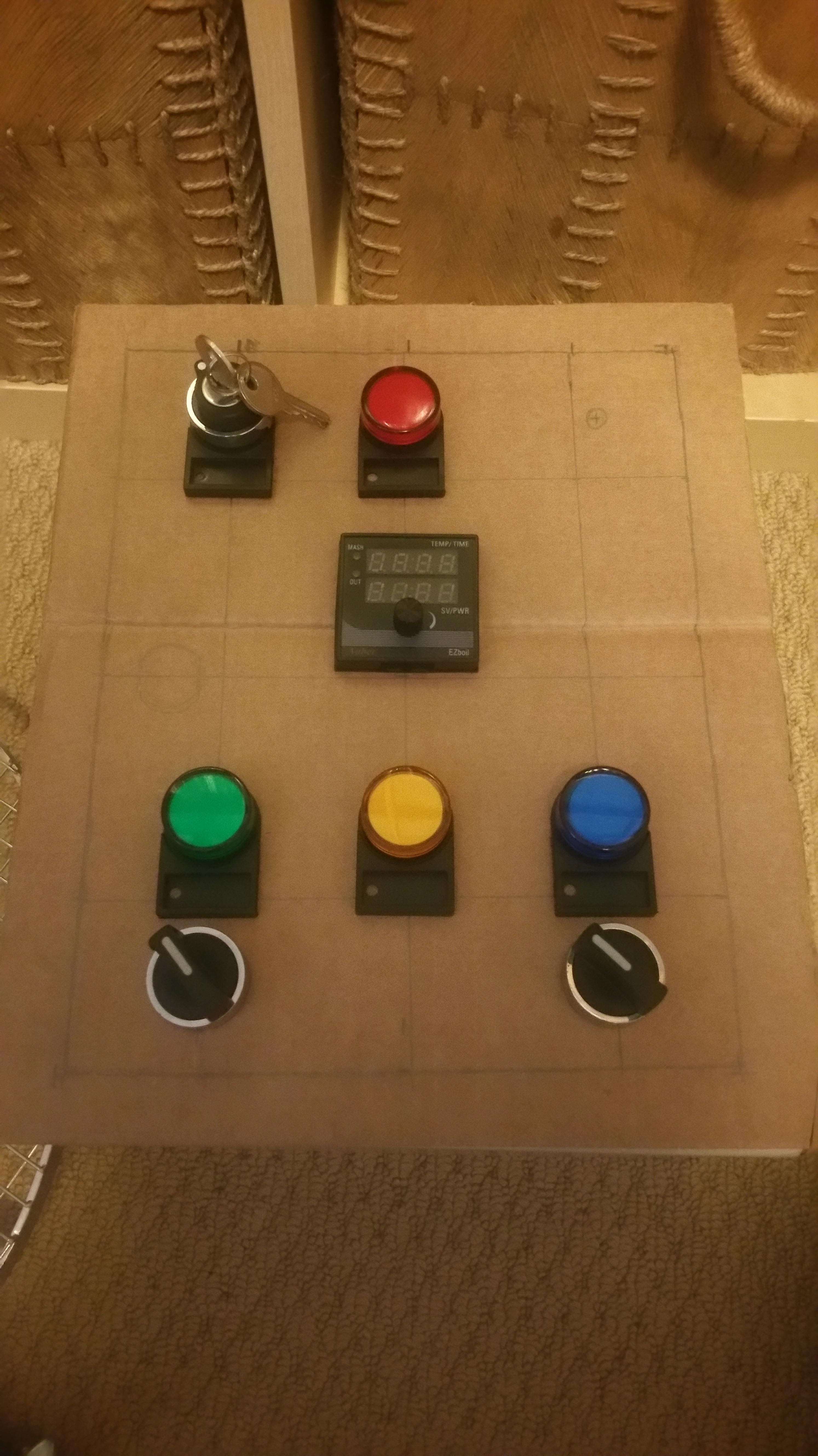
So I spent some time drawing things, making lists, learning and finally ordering up a ton of stuff from @Bobby_M , Auber and Amazon.

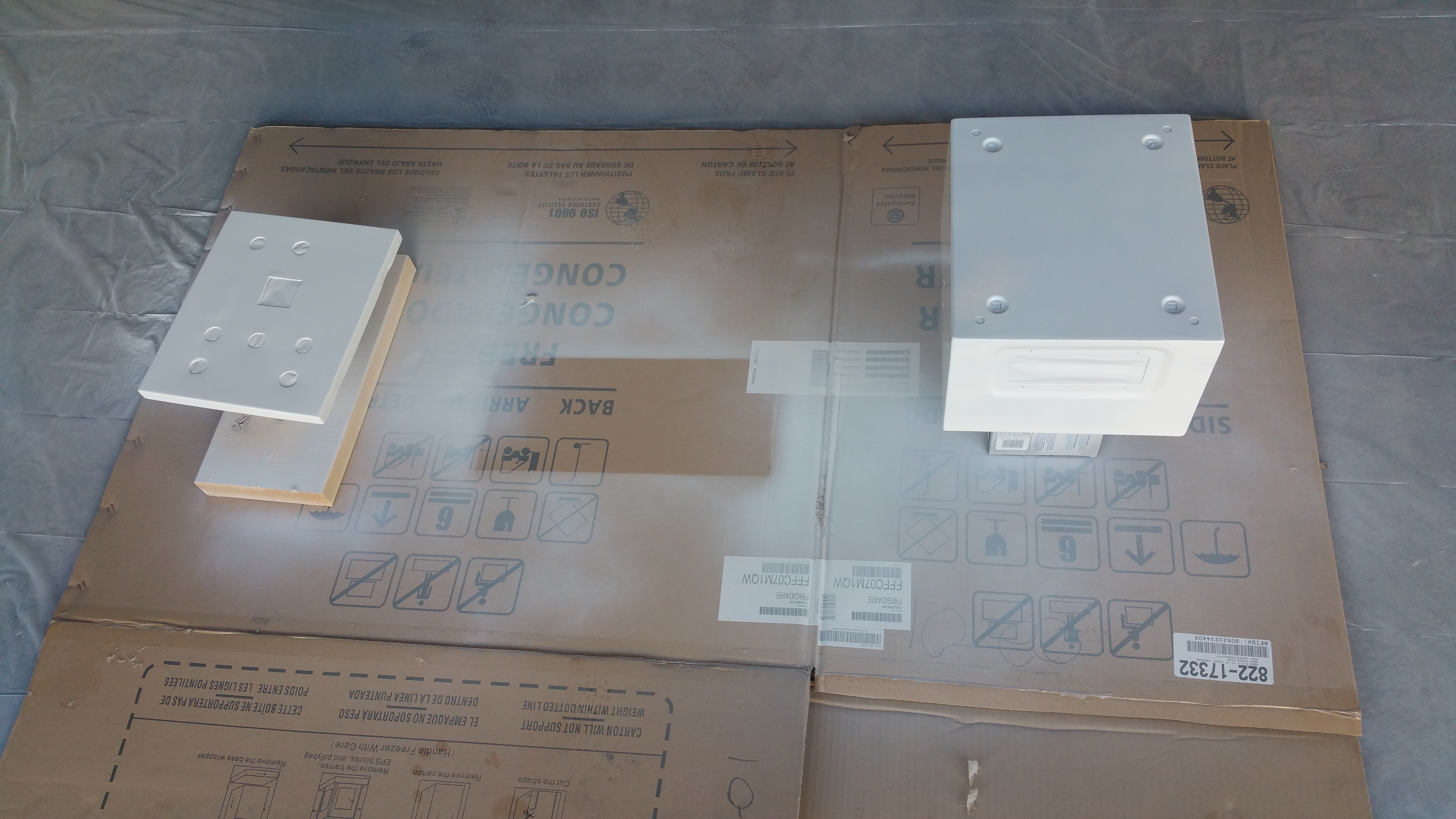
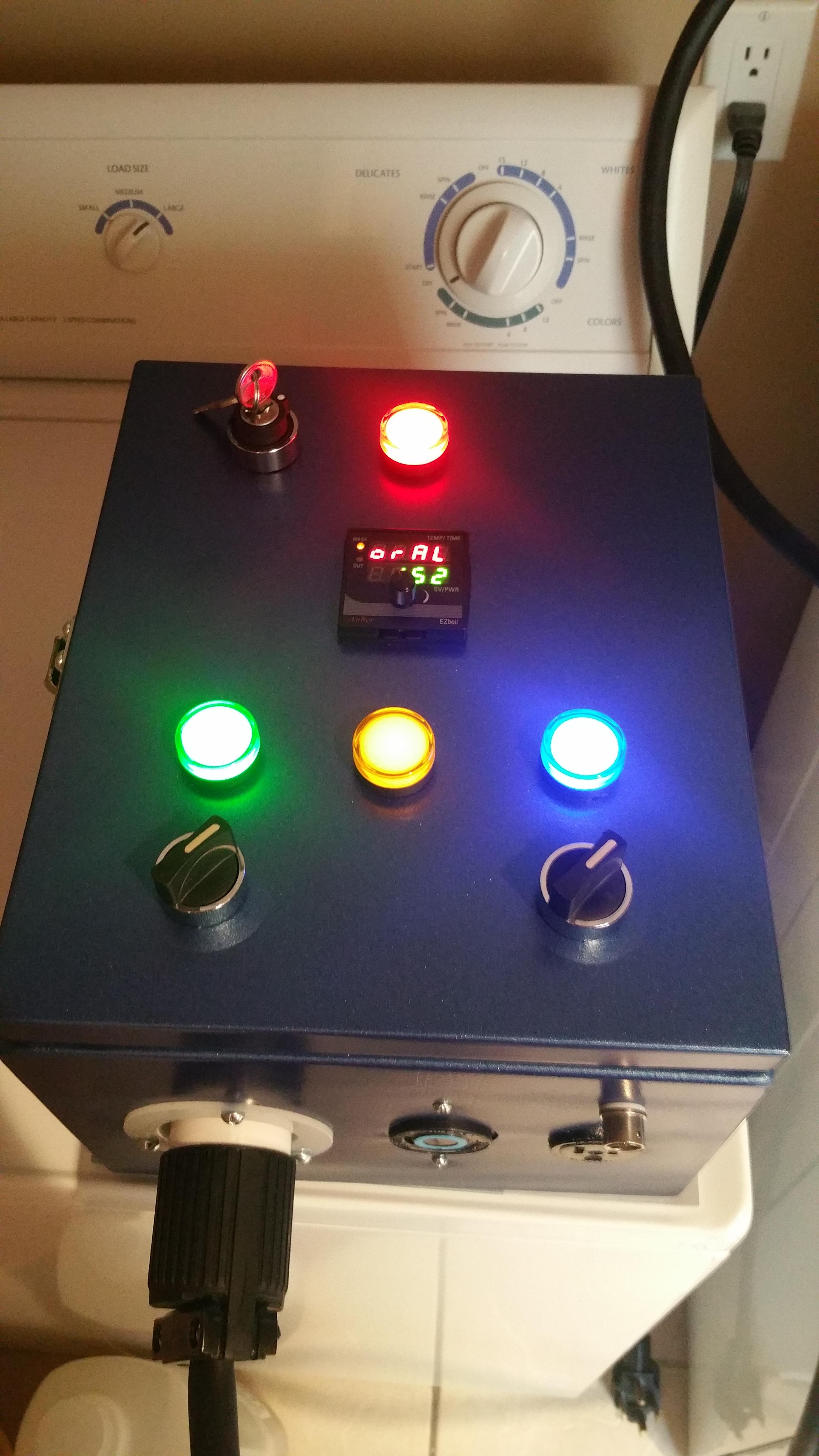
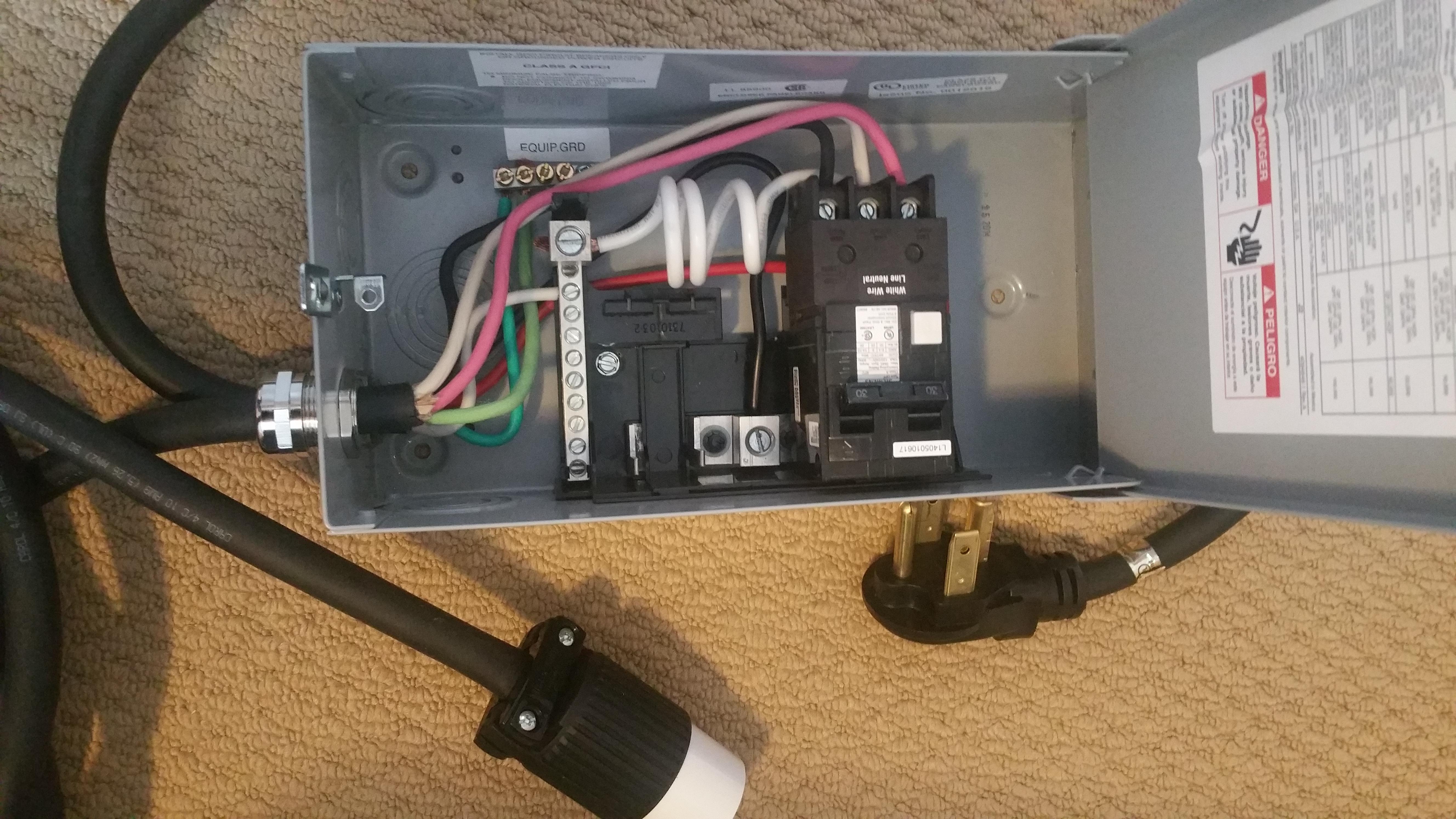
I will post some pics of where I am at currently and try to update things as the build progresses.
 
I wanted to fully understand the schematic before ordering parts and starting to wire it up, after looking over the great schematics from @doug293cz I decided to redraw the one that fit the closest in an effort to better understand it as well as have a modifiable version in case I wanted changes. The most obvious being the DSPR120, and marking the exact parts I would be using.

I drew it using Gliffy Diagrams if anyone is interested, its a Chome App.
https://chrome.google.com/webstore/detail/gliffy-diagrams/bhmicilclplefnflapjmnngmkkkkpfad?hl=en

r9qPSVh.jpg
 
I started a panel mockup drawing and came up with this.

b1XQBbA.png


Then I cut it out into a piece of cardboard as a realistic mockup to check fittings and spacing.

J0o0Kvh.jpg
 
I put the cable that runs from the control panel to the heater together, I am using the TC integrated element from @Bobby_M

u1RiwCT.jpg
 
I believe I am satisfied with my panel layout and have measured and marked it up on the actual panel to be drilled and cut. I hope to get that done in the next couple of days.

I will also be building up the spa panel and gfci portion as well.

I have some crazy ideas about not using the panel lock mechanism that came with the panel because I really dislike how it looks. We will see how that idea goes on my next few trips to homedepot.
 
I got my spa panel with 30A GFCI breaker all wired up and ready to go.

I will have this sitting on my dryer with the long 10/4 cord running to my brewing area and control panel.

gzy40LX.jpg
 
I wanted to get a better idea of where every wire would connect to be sure there was clearance for the number of connections at each device.

I put together this physical layout diagram of the internal components, the opened door (opens to the right) and the wiring layout.

I will likely run the wires crossing over to the door in a closer bundle, but this gives me a good idea how things will look.

(IMAGE UPDATED)
I have updated this image a few times to reflect the missing wire that was pointed out, as well as to show the ground wires hooking up to the panel and door posts. There were also a few small wiring location changes due to easier places to attach multiple wires while going through the actual wiring process.


kjST7Ua.png
 
Last edited:
Drilled out and cut the front panel for the switches, indicators and PID. Went fairly well, but the jigsaw got away on my on one side of the PID as you can see.

I can probably fix that in post-production.. or it will buff out.. or some such thing. :)

Front panel is sanded down for prime and paint, I just have to fill the original lock mechanism hole and see how much I can clean up the PID hole.

IDmeGW6.jpg
 
Here is a shot of the latch I will be using on the side to replace the original ugly front panel mechanism. This should look much nicer once the panel is all painted up and the parts are installed.

rH14ljj.jpg
 
I wanted to get a better idea of where every wire would connect to be sure there was clearance for the number of connections at each device.

I put together this physical layout diagram of the internal components, the opened door (opens to the right) and the wiring layout.

I will likely run the wires crossing over to the door in a closer bundle, but this gives me a good idea how things will look.

QdYTprk.png

You appear to be missing a neutral wire connection to the "Main Power On" indicator lamp (the one above the PID.)

Brew on :mug:
 
You appear to be missing a neutral wire connection to the "Main Power On" indicator lamp (the one above the PID.)

Brew on :mug:

Thanks! I knew I would miss something converting over to the layout. Will fix and update.
 
I believe your patience and research will pay off. I am sure you will have great satisfaction when you end up running your inaugural brew day.
 
Realized I really only have two components to mount on the backplane, the two contactors.

I had thought about using some terminal strips for wiring but with such a small ebiab build it was not really required after working out the physical wiring layout.

Drilled and mounted the contactors.

sSGv3Ot.jpg
 
Finished bondo job over the original lock mechanism hole and sanding. Pretty happy with how its looking so far, this part I was most worried about as it was going off the map a little.

Test fit all of the panel components again before priming.

CyHiAoz.jpg
 
My impromtu paint station in the garage and view of front panel after a few primer coats.

Going to let these fully cure and lay down the paint.

Can hardly wait to start assembly and wiring!

WemiaEg.jpg


KDC7YeA.jpg
 
Laid on the paint, its a Metallic Cobalt Blue.

Super happy with how its looking.

Going to let it dry a bit longer and put start putting the panel back together and attaching the hardware.

Uv0FXaU.jpg


zbHLjWO.jpg
 
Love the paint by the way. I’m getting depressed I sprayed mine black. And now I can’t change the color. I’m building another control panel and I want them to match. :(
 
Drilled the hole in the lid for the recirculation port. Used a 9/64 cobalt bit for the pilot hole and the Tungsten Carbide tipped hole saw from BrewHardware for the actual hole. I used a 3-in-1 oil to lube the process.

On the kettle side I still have to measure up the location for the 1.5" Triclover weldless bulkhead flange where the element will install and also the location for the temp probe.

Image of the test fit of the recirculation bulkhead and the whirlpool port (yes i realize its pointing up, just a test fit)

ljwZjD0.jpg


o7RGKYD.jpg
 
Last edited:
I still need to drill my lid. I’ll check out brewhardware

I wanted a barb for 1/2" silicone hose on the inside and camlock on the outside, brewhardware had what I needed. Not sure yet if I will just hang a hose down or run something more complex in there later, but for now thats what I wanted.

I went with this setup:
https://www.brewhardware.com/product_p/truebulkheadbarb.htm
https://www.brewhardware.com/product_p/nptelbowstreet.htm
https://www.brewhardware.com/product_p/cama.htm
 
I believe I have completed the wiring. Somewhat worried that I have missed something, so I will probably review my layout and schematic diagrams a few thousand more times before pulling everything into place with the zip ties and tie mounts. The wiring will hopefully look cleaner then, it follows a pretty consistent set of pathways but is currently hanging out of place due to weight and tension.

I am also going to cover the metal tape backing the bondo spots as it is pretty sharp and may cut into the wire if it rubs over time.

iOGBw4r.jpg
 
Took the system for a first power up test.

Put power to the spa panel first before plugging in the panel. Flipping the main breaker in my house panel to the dryer outlet and then the gfci breaker in the spa panel the first time was more than a little nerve wracking.

That went fine, so I plugged the panel in and turned the key. Main power light and PID came to life, turned the pump switch and the light for that came on, turned the element switch and that light and the element firing light came on.

I plugged in the temp probe to play with the PID a little and noticed that the element firing lamp is basically on all the time. It seems like once the element contactor is turned on and the lamp is getting one side of its hot plus maybe the SSR leakage is enough to light it about 50%

I do see it blinking between 50% & 100% when the element is firing rabidly when I adjust the PID temp close to its current temp. I am not sure if this is correct or how it works for everyone using this design, I guess I wish it was off/on not 50/100

Maybe @doug293cz or someone else could offer some suggestions here?

So far so good though. Probably move on to drilling more holes in my kettle next.

Can hardly wait for a wet test!


MfUkiJT.jpg
 
Maybe @doug293cz or someone else could offer some suggestions here?

You can put a small resistor parallel to the indicator inside the panel which should provide an alternative path for the leakage current in the SSR.

<edit> Also, your element should function as a nice big resistor when it's plugged in and should fix the problem ;)
 
You can put a small resistor parallel to the indicator inside the panel which should provide an alternative path for the leakage current in the SSR.

<edit> Also, your element should function as a nice big resistor when it's plugged in and should fix the problem ;)

Yes, the element firing light will illuminate as soon as the element contactor is engaged when the element is not plugged in. And yes, this is due to the leakage current thru the "off" SSR. It's the nature of the beast. With the element plugged in, it shunts the leakage current around the lamp, so the voltage across the lamp is very low (V = I * R, 5mA * 10ohm = 0.05V), The element firing light also pulses every time the SSR switches on and off, just like the element does. To stop this, you would have to put a low pass filter, with a time constant of about 2 seconds, in series with the element firing light. Would require a couple of 500V rated capacitors, and a high value inductor.

Edit: after rereading, it seems that you don't like the way the firing light pulses when the element is not plugged in. This will change when the element is plugged in.

Do not put a small resistor in parallel with the indicator light(s), it will burn up relatively quickly when the element SSR actually turns on. And they smell really bad when they burn. The element is a "small" resistor as far as resistance value. A 5500W element has a nominal resistance of 10.5 ohms.

Brew on :mug:
 
Last edited:
Right! I totally forgot that the circuit there would be different once the element is plugged in. I am OK with it pulsing and just want it to reflect the element state.

I will wait to see how it looks during the first firing test after the wet test. Can hardly wait.

Thanks again for the help!
 
Do not put a small resistor in parallel with the indicator light(s), it will burn up relatively quickly when the element SSR actually turns on. And they smell really bad when they burn. The element is a "small" resistor as far as resistance value. A 5500W element has a nominal resistance of 10.5 ohms.

Brew on :mug:

Thanks for jumping in Doug, although I am a bit curious now...

To fix the LED couldn't you use a 1watt 100k resistor across the 240?
 
Thanks for jumping in Doug, although I am a bit curious now...

To fix the LED couldn't you use a 1watt 100k resistor across the 240?

Without knowing the detailed IV characteristics of the LED lamp, you don't really know what value of resistor to use. 100K might do it, or it might not (and 100K is not a "small" resistance.) In any case, once you understand that it is an artifact of not having the element connected, it isn't a problem that needs to be solved.

Brew on :mug:

Very true, and you're quite right, my brain was thinking physically small.

Much better to just consider the half-lit indicator as a signal that you forgot to plug in your element :D
 
Got over my nervousness to drill holes in the side of my precious 15 gallon Ss Brewtech kettle.

Using the 9/64 carbide bit as a pilot bit along with a step bit for the temp probe and the 40mm Tungsten Carbide tipped hole saw made quick work of the holes. Super happy with the tools from BrewHardware for this build.

At this point I believe I have everything done and should be able to assemble everything and go for a wet leak test.

I guess one more thing I still need to sort out is how to hang the ratchet pulley that I got with my bag from The Brew Bag.

Another couple test fit shots.


O1YLbyO.jpg


cN1ArOJ.jpg
 
I have been busy but I had time to run an overnight leak test, filled kettle with 6 gallons above the whirlpool port and left it. Sitting on paper towel to better see any drips that may have happened overnight. The paper was clean in the morning, yay it seems to be sealed.

Later I hooked my pump first up to the kettle output and to the recirculation port in the lid and ran it for 10 mins then hooked it to the whirlpool port and ran it again for 10 mins. All ports seem to be working just fine.

Pumped all the water out and hopefully tomorrow I will replace the TC cap currently on there with the actual heating element. Then test heating some water and take some timings to mash and boil temps.

I have been reading over some of the other threads on eye bolts and how best to mount my ratchet pulley.
 
Filled the kettle to 8 gallons of water at roughly 15°C (60°F)

Raised it to 65°C (150°F) my test mash temperature in 22 minutes.

Left that to circulate for a while to see how it held and it was pretty good, I am happy with the ezboil so far.

Then I set it to boil mode and raised it up to boiling which took another 15 minutes.

I am VERY happy with the times, and so glad that I went all the way to build a 240V system. One of my big reasons to move to this ebiab system is to shave time off my brew day. I believe I will start looking into 45min or even less mash and boils soon as well.

I will continue to post any system updates and my first actual brew day, hopefully soon! Still need to sort out that darn ratchet pulley...


Edit:

Forgot to mention, the element light works perfectly and as expected with the element attached. Thanks everyone.
 
Last edited:
One of my big reasons to move to this ebiab system is to shave time off my brew day.

My favorite part about electric is the ability to ignore it during the brew day. I can set it to strike temperature before I start and then not worry if I get distracted, the water will be waiting for me whenever I've got the grain milled.

Same for the mash if you are able to get a stable recirculation going.
 
Still have to build up my table/stand and a few other things to keep things organized and going smooth on my brew days.

Today I will mostly be cleaning, my build took over much of my brewing areas and my keezer is covered in power tools, drill bits, files and bits of wire. Hopefully I will find time to get a brew going very soon to take the new system for a spin!

I will likely do an initial brew as things look below though since I can hardly wait.

A quick shot of the first water run test.

vtGJUZM.jpg
 
Back
Top