
Kayos
Well-Known Member
I put together a stir plate last night. Have tried 2 different 6v power adapters (cell phone chargers) and they won't turn the 80m comp. fan even when it's straight from the wall. 12v turns it fine. I hooked it all up and it's wayyy to fast. Dialed all the way down and the vortex is much too high.
Why won't the 6v charger do anything? Doesn't even sound like it's getting juice.
Why won't the 6v charger do anything? Doesn't even sound like it's getting juice.

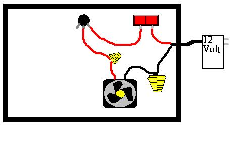
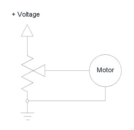


 The trouble is, he specifies part numbers for most components, and then just says "computer fan". Different fans have different RPMs, different current draws, etc. Digikey.com stocks 2400 different computer fans, and 1300 of them are 12v. Add in variation in magnets, power supplies, and mounting techniques and it gets complicated. 1-25ohms is a fairly narrow band for a potentiometer, and there are a lot of assumptions that go into getting that band to map properly from the right speed and torque for this application.