• Please visit and share your knowledge at our sister communities:
  • If you have not, please join our official Homebrewing Facebook Group!

    Homebrewing Facebook Group

StillDragon DIY Controller Kit

Homebrew Talk

Help Support Homebrew Talk:

This site may earn a commission from merchant affiliate links, including eBay, Amazon, and others.
Wow, good find. You could add another gfci for a 120 circuit as well, and be all set. Sure looks better than my spa panel

Sent from my SCH-I545 using Home Brew mobile app
 
If you aren't using 120 Volt (no 120v pump, PID powered by both hots etc ).you can install this GFCI:
http://www.ebay.com/itm/DIN-Rail-Mo...age-Circuit-Breaker-AC-230V-32A-/310571189555
or similar.

That looks great. 30ma sensitivity with less than 0.1s response time should be perfectly adequate, if I read the inverse-time curve charts correctly.

Back to the drawing board, lol.

Addendum: It looks like if I were to go with this GFCI and a 120v 15a duplex GFCI outlet, and change my plan to use DIN rail components, then I would net about $60 under the spa panel solution, with a cleaner build. YMMV
 
After pondering this a bit more, wouldn't you need a completely separate power feed for 120v? It seems to me that if you were to derive a 120v circuit from one leg of the 240v, this GFI would trip if current flowed through the neutral, unbalancing the two hots. Am I missing something here?
 
Not true, a 240V GFCI breaker manages 120V fine. It senses current between the red, white and black wires and as long as all three are in balance the breaker is happy. Only when the three are not in balance - current returning on the green wire or passing to ground, will the GFCI trip.

A connection between the red or black wire to white will be 120 VAC.

The GFCI in the link is 2 wire, not 3.

The little diagram shows the flux coil around only two wires, i.e., it is verifying that current down one leg = current back up the other. If you were to run a 120v circuit on this, the current down one hot leg would come back on the neutral, and appear like a ground fault. So that doesn't work.

If you have the two GFCI circuits in parallel, they should act just fine though. You are just creating two separate circuits, both with their own protection.

The problem is that you would then need 2 cords going between the panel and wherever your GFCI protection circuit enclosure is. You do not want the GFCI (or GFCIs) where the rest of the control electronics are.
 
No problem. Hope it will help:

dinrail.jpg


cover.jpg
 
As an aside, many households here in the states now have the 4 conductor plug/receptacles for the range and dryer circuits. Previously the 3 conductor solution would have been typical. But modern appliances now have control panel accessories (think clock) that are energized with 110/120 volts.

Previously the ground wire would have been used also as a neutral and then the clock would piggy back off of one of the 110/120 volt legs.
Evidently this became a no no. And so enter the 4 conductor solution we now see more and more of. Where by an extra wire would be needed to energize the lower voltage control panels on the modern appliances.

The StillDragon controllers are set up for HHG. However if you wish to add a 120 volt fan to your box, please do take advantage of your 4 conductor accommodation.

For setting up a "replacement" plug head for your service cord, simply do not install the contactor that would ordinarily be used to facilitate the neutral wire.

#10 service cord is recommended. Get the kind that has the soft rubber jacket. It's about $2 per ft.

The 300 volt is best if you want it to fit our PG-19 strain relief glands. The 600 volt will require a much larger gland.....Sorry I don't know how large.

The 300 volt service cord has a Blk/Wht/Grn set of wires. If you find the white wire to be too confusing then simply wrap some black or red electrical tape around it to identify it as HOT.

We do also offer larger size boxes for those of you who wish to add extra bells and whistles (or fans) to your control systems.

Though most systems (with a 5500 watt element) will not likely pull more than 22 amps, I am nearly positive your AHJ (building department) would insist on a 30 amp dedicated circuit if your work were to be inspected? They may accept a 25 amp? But I suspect many of you are not having your electrical work inspected.

Hope this helps.

Cheers
Larry
 
The peeps on the still dragon site are putting fans in their boxes. I thought drilling out some holes for vent would be sufficient?

http://www.stilldragon.org/discussion/comment/8961#Comment_8961

The holes are sufficient. I have been using one of these for about 5 years with out any issues. However many of our customers are installing fans to insure that they get an optimal service life out of the controller.

Furthermore, some users are installing multiple control stations in one (larger) box and so a fan in this instance would be best for displacing the heat generated.

I hope this helps
Larry
 
Perhaps I was being rather too charitable. This is the point that I was trying to get across.

The kit is advertised as a 5500W controller. But Lloyd StillDragon recommends a fan to operate at 5500W. So why isn't the fan in the kit :|

Firstly, the controller that we offer is originally intended for distilling. The 5500 watts (on a 5-10 gallon kettle charge) is only for rapid heat up. Once running temps are achieved, the controller would typically be dial back to 2200-3000 watts or so.

Secondly, the kits are just that. Kits to be assembled, modified, pimped out by the end user. For what is included, we really do offer the best value available.
All of the parts can also be ordered individually in case the end user wishes to source any other components else where.

I hope this helps.
 
Here is an example with no fan but does have a digital meter that displays Amperage and voltage.

little controller.jpg
 
Here is an example of a 3 station (element) controller. With this unit, a fan is used to help rapidly shed heat.

3 station controller.jpg
 
Glad I stumbled upon this. It'll help control my heating elements a hell of a lot easier.
 
This 3 wire breaker youve referenced is for only 240 right? Then if I want a simple 120 outlet for my pump then I'd need the four wire type breakers?
 
How does one wire an ammeter and a 3 selector switch into this box?

I'd like to pick up one of these but I want an ammeter for precise control as well as a 3 selector switch (two elements with off in the middle) to switch from one element to the other.
 
How does one wire an ammeter and a 3 selector switch into this box?

I'd like to pick up one of these but I want an ammeter for precise control as well as a 3 selector switch (two elements with off in the middle) to switch from one element to the other.

You're going to need a bigger box. You'll need two contactors, a three position (on-off-on) switch, and the ammeter at a minimum. Assuming 240V operation, one hot line gets connected to one input terminal on each contactor. The other hot line connects to the SSR power in. The SSR power out goes thru the coil on the ammeter, and then connects to the other input on each contactor. The outputs of the first contactor connect to the first heater, and the outputs of the second contactor connect to the second heater. One on position of the 3 way switch powers the coil of the first contactor, and the other on position powers the coil of the other contactor.

Might be cheaper and easier to get two of these controllers, one for each heater.

Brew on :mug:
 
6e0b170c61c03862837e4c77f264d5.jpg


This is the typical wiring I see on SD forums. Where does the switch, ammeter, and contactor fill in? What exactly is the contactor? I've seen a ton of wiring diagrams and I don't know what's needed or the order of them. My learning in electricity stopped at high school physics.

Does anything special have to happen for adding a 120V outlet as well for my pump?

And I priced the parts out and it's still cheaper I believe to get the stilldragon kit and go from there. I would get the larger box as well. HxWxL: 3.75"x7.25"x10.38"

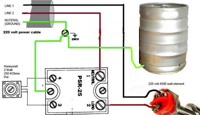
Here's a schematic of how to switch an SSVR (what the StillDragon controller is) between two different heating elements:

StillDragon 2 Heaters.JPG

If you don't understand the drawing, or how to actually implement the wiring, you should contact an electrician (or someone else knowledgeable.) Electricity can kill you if you get it wrong! :eek:

A contactor is an electromagnetic relay designed for switching high currents. They are activated using much smaller currents than they are controlling. The contactors for this application would be Auber Instruments CN-PBC302-120V (http://www.auberins.com/index.php?main_page=product_info&cPath=2_31&products_id=129), or similar. To control the contactors you need a three position, ON-OFF-ON switch like the Auber SW3 (http://www.auberins.com/index.php?main_page=product_info&cPath=7_32&products_id=235). Using this type of switch insures that you cannot connect the SSVR output to more than one heater at a time.

A 4 A slow-blow fuse will handle the contactor coil currents and a typical Chugger pump. You want a slow-blow fuse as the pump motor starting current is usually higher than the running current.

The Black, Red, and Purple hot wires, and the ground wires for the heaters all need to be 10 gauge stranded in order handle 30 A safely. The Hot Pink hot, and Gray neutral wires can be 14 or 16 gauge stranded as they don't have to handle more than 4 amps.

In order to have 120 volts available in your control box, the input power feed needs to be 4 wires (2 hot, 1 neutral, 1 ground). Without the neutral, you cannot have 120 V available.
This power feed should be protected by a 30 amp GFCI breaker or spa panel (which has a GFCI breaker.)

I forgot to add the ammeter to the schematic. Maybe I can get that done tomorrow.

Brew on :mug:
 
Last edited by a moderator:
Thanks! I don't get all the squiggly lines but I know someone who will haha.

That helps me get a parts list together. Think this will all fit in the larger box?

Also, my pump plugs into 120 AC plug (it's the tan little guy with AC adapter). Does the wiring change or would I just put an outlet where you see pump on there?

and is the potentiometer the blue box under the SSVR?
 
Thanks! I don't get all the squiggly lines but I know someone who will haha.

Good! Based on your questions, you need some guidance from someone more knowledgeable. It's for your own safety.

That helps me get a parts list together. Think this will all fit in the larger box?

I don't know how big that box is, or how big each of the component parts is, so I can't tell you if they will fit. Anyone who has built a control box will tell you that cramming everything into the smallest possible box will make it much more difficult to wire and service, and it will require service at some point. So, it's best to plan for that now.

The specific parts I linked are not the only options. They are examples of parts that are suitable for the job. Any part with equivalent specs should also work. You can often find cheaper parts on e-bay than the sources I linked.

Also, my pump plugs into 120 AC plug (it's the tan little guy with AC adapter). Does the wiring change or would I just put an outlet where you see pump on there?

Yes. People normally wire to an outlet in the control box, rather than hard wiring to a pump. Makes life easier.

and is the potentiometer the blue box under the SSVR?

The blue lines represent wires. The zigzag black line with an arrow touching it is the standard schematic symbol for a potentiometer (a variable resistor.)

Brew on :mug:
 
ok cool thanks. I'll try to finalize design plans and should I require more help maybe I trade you for help since we're both in Renton. Beer for electrical counseling? sounds like good ol fashioned bartering
 

Latest posts

Back
Top