Stc-1000+

Homebrew Talk - Beer, Wine, Mead, & Cider Brewing Discussion Forum

Help Support Homebrew Talk - Beer, Wine, Mead, & Cider Brewing Discussion Forum:

This site may earn a commission from merchant affiliate links, including eBay, Amazon, and others.
Yes, that's the instruction I followed to make the modification. As far as I know I completed it correctly and can't see that I could have caused the alarm to sound when on heating. Am I doing something wrong in my setup in manual mode that's causing the alarm to come on when heating? I've made sure the set point is above the ambient temperature.

try and run a profile and see if the alarm comes on then?
 
I've worked out what the issue is, when I made the modification I believe you are surposed to remove the relays, but I struggled to get them out so thought I'd leave them in. The noise I can hear is the relays buzzing and not the alarm.
 
@lewisash: Glad you worked it out. I was late to the discussion, but my suggestion would have been to check your soldering, as is seemed like a short between ICSPDAT and the relay control line. But, if the relay is still in there, then I agree with you, that is most likely the issue. You can't bridge if the relay is still there, you'll short it on contact, and that is why you get the buzzing. It will close, then then short and can't drive the coil, so it'll open, then voltage rises again and it'll close. This happening fast and repeatingly as long as the relay is driven or the tranny burns out from the shorts.

@IslandLizard: FYI, driving an SSR requires way less current than the mechanical relays. So, replacing the relay with an SSR is no problem.
 
I've worked out what the issue is, when I made the modification I believe you are surposed to remove the relays, but I struggled to get them out so thought I'd leave them in. The noise I can hear is the relays buzzing and not the alarm.

Good to see you got it sorted.
 
All sorted, I removed the relays and resoldered the connections and it works fine! Thanks for your help and suggestions.
 
Those STC 1000 units are tough little guys, they seem to take a lot of punishment. I thought that it might have been a jumper to the wrong place or something. (I have punished one unit badly and it still works)

Or that you found a bug in the code, but that seems extremely unlikely given that this version has been regularly used successfully. That and Mats is a gun at what he does... [emoji13]
 
... @IslandLizard: FYI, driving an SSR requires way less current than the mechanical relays. So, replacing the relay with an SSR is no problem.

Thank you, @alphaomega, Good to know, wasn't aware of that!
I was thinking along the line of an overload or a (near) short.
 
Hi folks.. I just signed up to participate in this thread.

I'm a homebrewer from Ottawa by night, and an embedded software guy by day. Looking forward to toying around with this code and looking for ways to optimize and improve for starters (sdcc is apparently a very sloppy compiler). For seconds, I'm looking to build a more robust ferm chamber algorithm. I typically tend to fab my own boards and stuff, but the STC is just so cheap off-the-shelf, that this is a great starting point.

Cheers!
Sean
 
while waiting for mods to approve my first posts, I did a bit of hand-optimizing of one if() statement and managed to save 110 bytes!
this if going to be fun!
 
Hi folks.. I just signed up to participate in this thread.

I'm a homebrewer from Ottawa by night, and an embedded software guy by day. Looking forward to toying around with this code and looking for ways to optimize and improve for starters (sdcc is apparently a very sloppy compiler). For seconds, I'm looking to build a more robust ferm chamber algorithm. I typically tend to fab my own boards and stuff, but the STC is just so cheap off-the-shelf, that this is a great starting point.

Cheers!
Sean

while waiting for mods to approve my first posts, I did a bit of hand-optimizing of one if() statement and managed to save 110 bytes!
this if going to be fun!

Hi Sean!

I'm glad you registered to HBT! I like to keep discussion of STC-1000+ here and not on github and I really welcome your input!
I agree that SDCC might not be the best compiler for the target (and I think the PIC targets are not their prime concern), but it is open and was a deciding factor. The STC-1000+ project is open and I like to use open tools as well as far as possible.

I agree that the price point is compelling :) Also, they are quite reasonably well designed (well, at least the A400_P ones).

Very cool! Did you modify the generated asm? STCC does support inline assembly and I would be open to use that if there are places where it does a lot of good. I have actually tried a couple of times to refactor the C code to make it generate smaller code. But I guess there are still places that could be improved or where asm would save space.

I've already told you, but I'll say it again, I really don't like PIC ASM. It seems like a mess to me (particularly the bank switching stuff). But still, if there is significant benefit to use it, then I'm for it. But I'd like to keep SDCC (and C), I don't want to switch to a closed source compiler or ASM altogether.

If you make progress (that is in line with STC-1000+) feel free to send pull requests (I'd prefer smaller chunks/changes if you do so). I'd also be open to suggestions.

If you want to discuss privately, send me a PM with your e-mail, and we can talk over mail if you feel you have stuff to talk about that does not belong here, otherwise I like to keep it public so others can benefit from the discussion as well.

Cheers!

Edit: Oh, and if you do write some C code, beware that there is a bug in SDCC, that local static variables are not initialized. You need to make them global. Bit me in the a$$ when I started this project.
 
Very cool! Did you modify the generated asm? STCC does support inline assembly and I would be open to use that if there are places where it does a lot of good.

I didn't bother modifying any of the generated code.. just some refactoring of the C was enough to start seeing savings. I'm going to just probably profile the compiler output and see what sort of constructs it is absolutely horrid at and see if there are any common patterns that produce smaller code. Agree, the bank-switching is a bit klunky.. keeping variable accesses grouped would be one way to reduce that, but the compiler seems very naive sometimes (for example: if (condition) { bank switch; set variable } else { bank switch; set same variable }. bank switched on both branches :( Some of those areas are pretty low value for optimization though... but some others like int = int >> 8; also produce wasteful code with unnecessary extra instructions. something like that is a good candidate for hand-coding in assembler as a SHIFT8 macro or similar.

I've started putting together a list of best practices for this development environment, and we can sync up on that as I learn more.. it's only been a few hours working with this architecture :p

Edit: Oh, and if you do write some C code, beware that there is a bug in SDCC, that local static variables are not initialized. You need to make them global. Bit me in the a$$ when I started this project.

I saw that in your docs.. thanks for the heads up!
Expect some simple diffs shortly :)
 
I didn't bother modifying any of the generated code.. just some refactoring of the C was enough to start seeing savings. I'm going to just probably profile the compiler output and see what sort of constructs it is absolutely horrid at and see if there are any common patterns that produce smaller code. Agree, the bank-switching is a bit klunky.. keeping variable accesses grouped would be one way to reduce that, but the compiler seems very naive sometimes (for example: if (condition) { bank switch; set variable } else { bank switch; set same variable }. bank switched on both branches :( Some of those areas are pretty low value for optimization though...

I hear ya! I have done some C optimization, but I haven't analyzed the generated code, but I think you are totally right. I've just tweaked until what I needed to fit, would fit :)

but some others like int = int >> 8; also produce wasteful code with unnecessary extra instructions. something like that is a good candidate for hand-coding in assembler as a SHIFT8 macro or similar.

That should actually generate no code at all :) That should just be the top 8 bits (i.e. the high register) of a 16 bit variable. (Depending a bit on the usage, but in all probability, what is ment by your example is rather char = int >> 8).

[/QUOTE]
I've started putting together a list of best practices for this development environment, and we can sync up on that as I learn more.. it's only been a few hours working with this architecture :p
[/QUOTE]

Very nice!!! I'll gladly add this to the wiki on github, if you're willing to share :)

I saw that in your docs.. thanks for the heads up!
Expect some simple diffs shortly :)

Looking forward to it!!!
 
That should actually generate no code at all :) That should just be the top 8 bits (i.e. the high register) of a 16 bit variable.

it's a shift & store. but they go and unnecessarily zero things in some spots. Perhaps better described as int >>= 8; it crops up in the eeprom programming code :)

here's a tip along the same lines: if you've got an int, but it's not going to be >255, then it's best to just assign it to a new variable (space permitting) if it's going to be used much subsequently. e.g., in value_to_led(), assigning unsigned char v=divu10(value) saves a fair bit.

anyhow.. I'll aggregate some of these tonight and see about pushing something over.. I hate git ;)
 
Nice!
Can't wait :)
I love git, I just can't wrap my head around it :) I grew up with CVS and SVN, and as much as they sucked, at least I understood them :)
 
First I need to thank smithabusa since it was his website that helped me find this great thread. I purchased a STC1000 from a local brew supply store when I was getting ready to control my first batch of beer to be fermented from my new Pico Brew Zymatic. Later I learned I was lucky enough for it to be one I could flash to this great software. Since then I purchased 6 more from smithabusa and they all flashed no problems.

One of them however doesn't want to power the screen when connected to 110VAC. It still power up just fine off the Arduino Nano and I'm using this one at my tester for now. Anyone else have this kind of issue with an STC1000?

I flashed all 5 of my units with the picprog_com software version in F and 2 others C for a buddy. I have left the 5v line off since I didn't have diode handy and there is not a single place where I live to get any electronics. I have a batch fermenting right now with the arduino connect to a Gen 1 RPi and I can VPN to my home network and VNC to the RPi and check the status. I'm noticing some weird things with the register mapping. Then I use the Arduino serial monitor I can read the Temp, heating and cooling status, then all report back normal. But the SP and hy parameters are not working like they should. My SP is 73.0 and it reports back as 0 and my hy is set to 0.5 and reports back as 73.0 I flashed v1.09 I went looking through he code as best I could and could not find details on the mapping or how I can fix what I suspect is a mistake in the register mapping. I was not sure where to ask this question here or Git.

My plan is to as some code to stream Temp, SP, Heating and Cooling status every 5 seconds. The have the RPi read and log that. I will then use a script to upload to my Dropbox every hour so even from work I can look at my progress and the heating or cooling duty cycles. I'm eventually (next few weeks) going to have 4 fermentors going each with their own STC all reporting to a RPi 2 and the fith STC1000+ will running my glycol chiller for my SSBrewtech Mini Buckets that have chilling coils installed.

Thanks,

Lee

Screen Shot 2016-01-22 at 7.12.18 PM.png
 
First I need to thank smithabusa since it was his website that helped me find this great thread. I purchased a STC1000 from a local brew supply store when I was getting ready to control my first batch of beer to be fermented from my new Pico Brew Zymatic. Later I learned I was lucky enough for it to be one I could flash to this great software. Since then I purchased 6 more from smithabusa and they all flashed no problems.

One of them however doesn't want to power the screen when connected to 110VAC. It still power up just fine off the Arduino Nano and I'm using this one at my tester for now. Anyone else have this kind of issue with an STC1000?

Measure the 5v line when powered from mains. Sounds like the voltage regulator, it's a TO-92 package component between two capacitors and just to the side of the buzzer.

I flashed all 5 of my units with the picprog_com software version in F and 2 others C for a buddy. I have left the 5v line off since I didn't have diode handy and there is not a single place where I live to get any electronics. I have a batch fermenting right now with the arduino connect to a Gen 1 RPi and I can VPN to my home network and VNC to the RPi and check the status. I'm noticing some weird things with the register mapping. Then I use the Arduino serial monitor I can read the Temp, heating and cooling status, then all report back normal. But the SP and hy parameters are not working like they should. My SP is 73.0 and it reports back as 0 and my hy is set to 0.5 and reports back as 73.0 I flashed v1.09 I went looking through he code as best I could and could not find details on the mapping or how I can fix what I suspect is a mistake in the register mapping. I was not sure where to ask this question here or Git.

Doesn't matter, now I know :) Thanks for that I'll look into it when I get a chance. It does sound like a register mapping that is off.

My plan is to as some code to stream Temp, SP, Heating and Cooling status every 5 seconds. The have the RPi read and log that. I will then use a script to upload to my Dropbox every hour so even from work I can look at my progress and the heating or cooling duty cycles. I'm eventually (next few weeks) going to have 4 fermentors going each with their own STC all reporting to a RPi 2 and the fith STC1000+ will running my glycol chiller for my SSBrewtech Mini Buckets that have chilling coils installed.

Thanks,

Lee

Sounds cool! Post a pic if you can!
Thank you!
 
@ldzielak: Hopefully I have fixed the com.ino sketch now. At one point I refactored the menu system in the STC-1000+ code and forgot to change com.ino. Unfortunately, with my current setup, I cannot test com stuff, so I couldn't verify that the change I made is correct, but it'll hardly make it worse at least ;)

Cheers!

Sounds good, I will test it out tonight. I'm away for work till the 2nd but I have one unit with to do some testing.

So do you think it will be possible for me to modify your com.ino to print a simple CSV formatted string with Temp, SP, Cooling and heating status, while retaining all the existing features? I really want to log the data, but don't want to loose any of the great features you have created.

I don't have much for pictures on me with my setup, I was sent the wrong thermowells for the mini buckets so I didn't drill the holes in the lids yet. Here are some in progress pictures.

Cheers Lee

IMG_1112.jpg


IMG_1114.jpg


IMG_1123.jpg


IMG_1132.jpg
 
So do you think it will be possible for me to modify your com.ino to print a simple CSV formatted string with Temp, SP, Cooling and heating status, while retaining all the existing features? I really want to log the data, but don't want to loose any of the great features you have created.

Sure, it is kind of the point with the com firmware. Just a tip though, don't send commands too quickly (that is, use a delay beween each command sent of at least 10ms). Due to limitations with the protocol, communication state resets after 10ms, so if there is a cimmunication error, it allows next command to have a chance to start 'clean'. Otherwise the error may propagate.

Thanks for the pics! Let me know if the fix I put up doesn't work out. Good luck!

Cheers!
 
Hi all...long time lurker, first time contributor here. First, I want to thank Mats for all of his hard work on this project. I appreciate it more than I can ever repay you for your contributions.

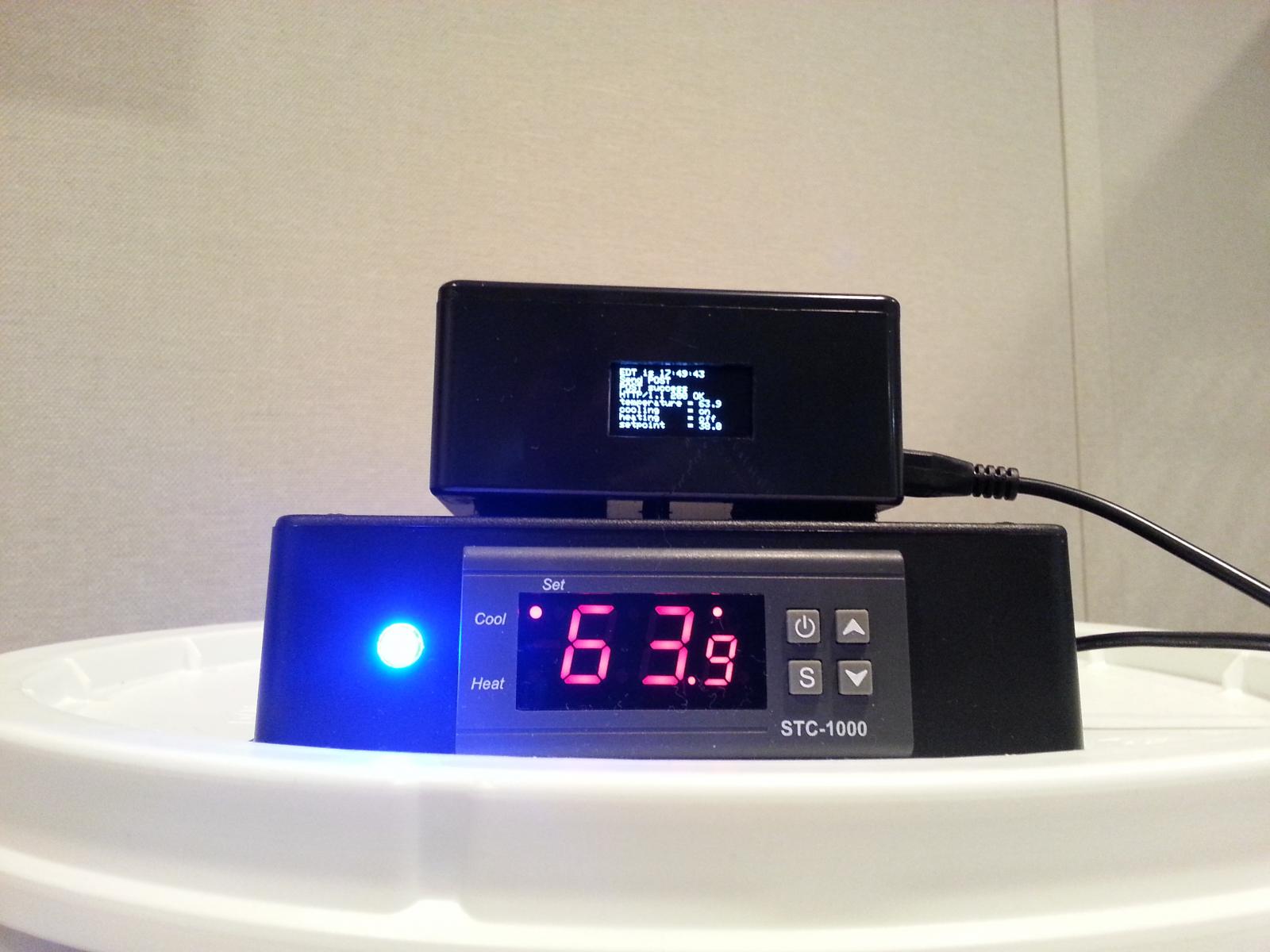
For some time I've been working on a wireless logger for the STC-1000+, based on the communications firmware Mats wrote. I've been through a number of iterations on this going back almost a year now, and have something I'd finally like to share. It's based on the Adafruit Huzzah ESP-8266 package, which I find quite stable and love the 4M flash available. It also is cheap (about $10).

I've set up a Git repository with the code (written in / for the Arduino IDE) and additional details. The project also supports an OLED display to keep track of what's happening in real time. It gathers information from the running STC (setpoint, status of heating / cooling relays, current probe temp, run-mode (profile or thermostat), step (for profile), and duration hours. This data is streamed to an on-line datastream at Sparkfun (data.sparfun.com), or you can change this to a local Phant server if you prefer.

The repository includes a (crude) Fritzing diagram to show how I connected the components. When I started this, I was a noob working with electronics, soldering, using the Arduino, Github, Fritzing, etc., so please be kind in your criticisms / feedback.

There are a number of things that need to be edited in the code before compiling it, such as specifying your SSID, password, network IP info, NTP settings, timezone offset, Sparfun datastream keys, etc. These are all flagged in the code and detailed in the README. I hope to continue to enhance this by adding a web configurator in the future to handle these settings rather than having to edit the code directly, but it is what it is for now.

Good luck and please let me know if you get a chance to try it out how it works for you.

Here's the Github link: https://github.com/fowlerk/STC1000Logger.git

20160124_175003.jpg
 
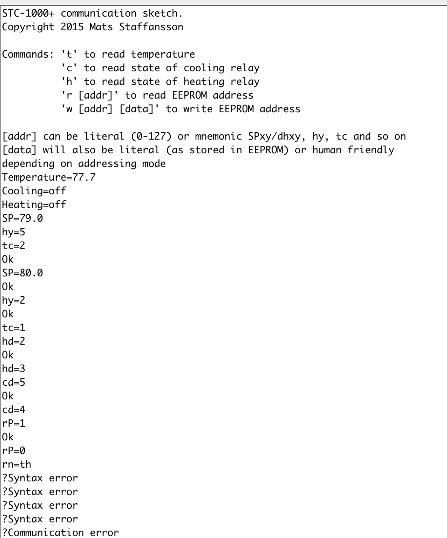
Well here is some testing results from the new com.ino

I tested both reads and writes. Looks like the only things I can find wrong are a few of the variables need to be divided by 10, hy, tc & SA (not a very big deal at all!)

rn parameter had me confused based on the comments next to them in the code. I could not write 0-6, but I can write th or Pr0... So I guess this works as intended. All other parameters I have tried writing to work just like they should.

Reading St and dh would not work until I had used a profile for a moment, then even after being back in th mode, I could read these parameters. Make sense now.

It kinda would be nice to see more info than just Ok after a write, like echo back what the parameter and value written was, but on the other hand from a script confirmation, this is all that is needed.

Thanks for the quick fix.

Lee

Screen Shot 2016-01-24 at 8.23.02 PM.png
 
Sure, it is kind of the point with the com firmware. Just a tip though, don't send commands too quickly (that is, use a delay beween each command sent of at least 10ms). Due to limitations with the protocol, communication state resets after 10ms, so if there is a cimmunication error, it allows next command to have a chance to start 'clean'. Otherwise the error may propagate.

Thanks for the pics! Let me know if the fix I put up doesn't work out. Good luck!

Cheers!

So my thinking was this, please correct me if I'm miss understanding your com.ino It is always waiting for a request and simply carries out orders when it gets a new command, then goes back to waiting for the next command.

My concept is after waiting for 5 seconds, Arduino would query to STC for current SP, Temp, Cooling/Heating status (Maybe checking rn and if running a profile, report back the St and dh) These questions would be asked one at a time with 10+ms between them, compact the results into a single string (coma separated) and then print to serial. Something like "80.0,79.9,off,on,PR0,1,48" this would then take say 80-100ms to collect and print. Then go back to monitoring for the next command for another 5 seconds.

Next step after getting this to work is a GUI or virtual control panel where I can see my STC1000+, being updated every 5 seconds, and maybe make the buttons function just like I was really at the STC. Depending on what you select, the equivalent command would be sent to the STC and GUI would update. I would build my 5 STCs into a single interface and I could manipulate as desired from anywhere I can VPN and VNC to my RPi 2. (Want to go real crazy, make an iPhone/andriod app and interface / trend results from anywhere)

I come from an instrumentation/ advanced controls and analyzer background, 18yrs in pulp and paper and now 3yrs in oil. I have been programming Emerson DeltaV DCS for 8 years now, Metso DNA before that. I'm used to multi million dollar control systems and multi billion dollar plants. I now do controls consulting and configuration for a big oil company. I'm dreaming of having the same control over my fermentation at home as I do every day over massive advanced processes!

Cheers
 
Hi all...long time lurker, first time contributor here. First, I want to thank Mats for all of his hard work on this project. I appreciate it more than I can ever repay you for your contributions.

For some time I've been working on a wireless logger for the STC-1000+, based on the communications firmware Mats wrote. I've been through a number of iterations on this going back almost a year now, and have something I'd finally like to share. It's based on the Adafruit Huzzah ESP-8266 package, which I find quite stable and love the 4M flash available. It also is cheap (about $10).

I've set up a Git repository with the code (written in / for the Arduino IDE) and additional details. The project also supports an OLED display to keep track of what's happening in real time. It gathers information from the running STC (setpoint, status of heating / cooling relays, current probe temp, run-mode (profile or thermostat), step (for profile), and duration hours. This data is streamed to an on-line datastream at Sparkfun (data.sparfun.com), or you can change this to a local Phant server if you prefer.

The repository includes a (crude) Fritzing diagram to show how I connected the components. When I started this, I was a noob working with electronics, soldering, using the Arduino, Github, Fritzing, etc., so please be kind in your criticisms / feedback.

There are a number of things that need to be edited in the code before compiling it, such as specifying your SSID, password, network IP info, NTP settings, timezone offset, Sparfun datastream keys, etc. These are all flagged in the code and detailed in the README. I hope to continue to enhance this by adding a web configurator in the future to handle these settings rather than having to edit the code directly, but it is what it is for now.

Good luck and please let me know if you get a chance to try it out how it works for you.

Here's the Github link: https://github.com/fowlerk/STC1000Logger.git

Very cool :)
I don't know if you have followed this thread, but I actually played around with the ESP myself. I used a framework called Sming, which has Arduino support + a lot of other cool things. But I never got it working reliably. So, I kind of lost faith in it for a while.

Turns out though, that there was a bug in the JSON library that Sming uses (memory leak), that recently got fixed. Tried it out a few days ago, and it seems to work a lot better now, so I'm kind of in the mood to get started with it again.

I had a PoC going that starts an AP (WiFi access point) when not configured. Connect to it and configure your network (or simply use the AP if you want to). It can do all the COM stuff via simple REST interface AND you can FTP a HEX file and update the STC-1000+ firmware.

It needs some polishing, I'd like to get a modified version of the profile editor running, so you can simply edit your profile, upload and run it directly. Some logging (either to flash or cloud) would be cool as well. Waddaya think?

I don't mean to steal you thunder, on the contrary, that is a very cool project! Kudos! (Maybe I should have lead with that...)
But I don't have a lot of spare time on my hands, and if I can get others interested in contributing, that would make it a lot more likely to happen. I can share what I got right now, but I'd probably need to clean it up a bit first. So far it is mainly based on the Sming examples + the COM and picprog sketches. It is still very crude... But it shows potential. It would be cool to combine the cheap but reliable STC, with the cheap (but somewhat less reliable) WiFi capabilities of the ESP to make something really great.

Well here is some testing results from the new com.ino

I tested both reads and writes. Looks like the only things I can find wrong are a few of the variables need to be divided by 10, hy, tc & SA (not a very big deal at all!)

rn parameter had me confused based on the comments next to them in the code. I could not write 0-6, but I can write th or Pr0... So I guess this works as intended. All other parameters I have tried writing to work just like they should.

Reading St and dh would not work until I had used a profile for a moment, then even after being back in th mode, I could read these parameters. Make sense now.

It kinda would be nice to see more info than just Ok after a write, like echo back what the parameter and value written was, but on the other hand from a script confirmation, this is all that is needed.

Thanks for the quick fix.

Lee

Ok, I buckled down and broke out an STC that I could use for COM stuff and think I've fixed the remaining issue.
Reading/writing St and dh should be doable, even without first running a profile.
Yes, rn accepts "th", "Pr0"-"Pr5" (just as it shows them that way).
It can't really do more than write "Ok" as, all it knows is that the communication worked. You really need to read the same value again, if you want to verify that it really was written correctly.

So my thinking was this, please correct me if I'm miss understanding your com.ino It is always waiting for a request and simply carries out orders when it gets a new command, then goes back to waiting for the next command.

My concept is after waiting for 5 seconds, Arduino would query to STC for current SP, Temp, Cooling/Heating status (Maybe checking rn and if running a profile, report back the St and dh) These questions would be asked one at a time with 10+ms between them, compact the results into a single string (coma separated) and then print to serial. Something like "80.0,79.9,off,on,PR0,1,48" this would then take say 80-100ms to collect and print. Then go back to monitoring for the next command for another 5 seconds.

Next step after getting this to work is a GUI or virtual control panel where I can see my STC1000+, being updated every 5 seconds, and maybe make the buttons function just like I was really at the STC. Depending on what you select, the equivalent command would be sent to the STC and GUI would update. I would build my 5 STCs into a single interface and I could manipulate as desired from anywhere I can VPN and VNC to my RPi 2. (Want to go real crazy, make an iPhone/andriod app and interface / trend results from anywhere)

I come from an instrumentation/ advanced controls and analyzer background, 18yrs in pulp and paper and now 3yrs in oil. I have been programming Emerson DeltaV DCS for 8 years now, Metso DNA before that. I'm used to multi million dollar control systems and multi billion dollar plants. I now do controls consulting and configuration for a big oil company. I'm dreaming of having the same control over my fermentation at home as I do every day over massive advanced processes!

Cheers

Ok, first off. It wouldn't be that hard to change the loop function in the com.ino sketch to every 5 seconds fart out the stuff you want over serial. That would be a very good beginning exercise.

Next, if you modify the sketch, I don't see a problem in communicating with 5 STC's with one Arduino. You really only need one data pin per STC. But you'd need to write some code to address them. You could add an arduino per STC as well. If you're gonna write a GUI, then you can't have it blurt out stuff every 5 secs, so you'd need to go back and just have the GUI poll the stuff it needs over serial. But I guess that is a given.

From experience, I know serial can be a bit tricky, so you'd need some decent error handling. And for the GUI, I'd suggest you use absolute addressing (i.e. "r 125" and "w125 0" for example) instead of the mnemonics. That is why the absolute addressing is there, to make it easier to interface with a computer. The mnemonics is easier on a human :)

Good luck!
 
Very cool :)
I don't know if you have followed this thread, but I actually played around with the ESP myself. I used a framework called Sming, which has Arduino support + a lot of other cool things. But I never got it working reliably. So, I kind of lost faith in it for a while.

Turns out though, that there was a bug in the JSON library that Sming uses (memory leak), that recently got fixed. Tried it out a few days ago, and it seems to work a lot better now, so I'm kind of in the mood to get started with it again.

I had a PoC going that starts an AP (WiFi access point) when not configured. Connect to it and configure your network (or simply use the AP if you want to). It can do all the COM stuff via simple REST interface AND you can FTP a HEX file and update the STC-1000+ firmware.

It needs some polishing, I'd like to get a modified version of the profile editor running, so you can simply edit your profile, upload and run it directly. Some logging (either to flash or cloud) would be cool as well. Waddaya think?

I don't mean to steal you thunder, on the contrary, that is a very cool project! Kudos! (Maybe I should have lead with that...)
But I don't have a lot of spare time on my hands, and if I can get others interested in contributing, that would make it a lot more likely to happen. I can share what I got right now, but I'd probably need to clean it up a bit first. So far it is mainly based on the Sming examples + the COM and picprog sketches. It is still very crude... But it shows potential. It would be cool to combine the cheap but reliable STC, with the cheap (but somewhat less reliable) WiFi capabilities of the ESP to make something really great.

Yeah, I didn't elaborate in my original post (it was long enough already!), but you were my inspiration for this! I took a quick look at Sming and played around with the ESP-01, but then ESP support was added to the IDE (with which I was already familiar), and I was having issues with the ESP hanging. So, I looked around and found the Cactus Micro (combo ESP and ATmega32U4), and got the initial version running on it. Again, had issues with it hanging after anywhere from hours to days, and I didn't have flash to add much error handling. That's when I moved on to the Huzzah. So far, it's been rock-solid. It's a little more expensive ($10 US), but I like the flash size (4M= lots of future functionality!) I'm actually working on adding the web configuration you mentioned, but I really like your ideas on the OTA updates, profile editing, and local logging options. I'm not nearly at your level of coding expertise (or electronics), but I can generally read and follow other's code. (Oh, and borrow judiciously!)

All that said, I'd be happy to contribute where I can once you can get the opportunity to put up what you've written.
 
hey folks.. does anyone have a part number for an appropriate 3-pin terminal block to replace the 2-pin probe one for a multiprobe setup?

Anyone happen to know the pitch of the holes? looks like 5mm?

No need to use the same 10A/300V rated ones that are on there already... maybe this one here? http://www.digikey.ca/product-detail/en/1935174/277-1578-ND/568615
(Edit: I was sorting by price, and wouldn't you know it, a HIGHER current part was cheaper :p Here's a similar 10A/300V one for a few cents more I guess -- http://www.digikey.ca/product-detail/en/OSTYC032150/ED2903-ND/1588995 )

Cheers,
Sean


Just going from memory, I think the 2nd one looks like what I got. But I got mine off eBay from Hong Kong.
 
Could you please give me a hand understanding the use of programs with ramping enabled?

Lets say that I program the controller such PR0 is:

SP0 20.0
dh0 72
SP1 18.0
dh1 24
SP2 10.0
dh2 0

If I start PR0 on step 0, the controller will set SP to SP1 (20.0) and over a lapse of dh0 (72 hrs) the SP will gradually change towards SP1 (18.0) after which, SP will gradually change over a lapse of dh1 (24 hrs) towards SP2 (10.0) after which it will no longer change.

Is that right?

Thanks!

Yes that's the ramping process. See this link for building and 'seeing' what you set using Mats profile builder.
 
Mats, any chance you could hop over to the PI (mashing) thread and comment on my post from a few days ago? I'm working on testing this version with my setup, in F, and not really sure where to start with the settings.

Any chance the profile builder page will get updated to include this one?
John
 
Yeah, I didn't elaborate in my original post (it was long enough already!), but you were my inspiration for this! I took a quick look at Sming and played around with the ESP-01, but then ESP support was added to the IDE (with which I was already familiar), and I was having issues with the ESP hanging. So, I looked around and found the Cactus Micro (combo ESP and ATmega32U4), and got the initial version running on it. Again, had issues with it hanging after anywhere from hours to days, and I didn't have flash to add much error handling. That's when I moved on to the Huzzah. So far, it's been rock-solid. It's a little more expensive ($10 US), but I like the flash size (4M= lots of future functionality!) I'm actually working on adding the web configuration you mentioned, but I really like your ideas on the OTA updates, profile editing, and local logging options. I'm not nearly at your level of coding expertise (or electronics), but I can generally read and follow other's code. (Oh, and borrow judiciously!)

All that said, I'd be happy to contribute where I can once you can get the opportunity to put up what you've written.

Ok, so I've got a repository up on github. I've still not cleaned up the code and it lacks documentation, but at least the code is there. It is just proof of concept stuff, but still pretty cool that it works. Now, the real work begins... *sigh*
 
Ok, so I've got a repository up on github. I've still not cleaned up the code and it lacks documentation, but at least the code is there. It is just proof of concept stuff, but still pretty cool that it works.

Okay Mats, I'll head over and take a look. No worries on cleaning up the code / documentation at this point. Give me a few days to wrap my head around Sming and what you've posted and I'll see if I can contribute.

Now, the real work begins... *sigh*
...And that's the "fun part", right? :)
 
Well, optimization has been going well.. I think we've shaved down around 15% of the code so far, and probably room for another 5% or so. Should be lots of space for new dual-probe algorithms.
I'm going to rig a unit up with dual probe and 1-wire comms on the heating relay pin and do some real-world data logging soon in order to build some nice models for simulation. Then should be able to settle on an effective algorithm :)
 
I've been making pretty good progress with the ESP stuff. Greatly improved on the HEX flashing. Now you can load a page (hosted on the ESP) and stream the HEX file over a websocket to the ESP, that flashes the STC on the fly. The profiles should be editable (using a modified version of the profile editor). There is a page for the set menu.
The major parts left are:
* Logging
* Documentation
* And oh my <insert deity of choice>, does the code need to be cleaned up. The web pages needs polishing and a consistent interface (which I suck at), and there are a lot of minor improvements to be done.

But over all, now it works pretty smooth! I think this could be good given time and some TLC :)


This is awesome.:ban:
 
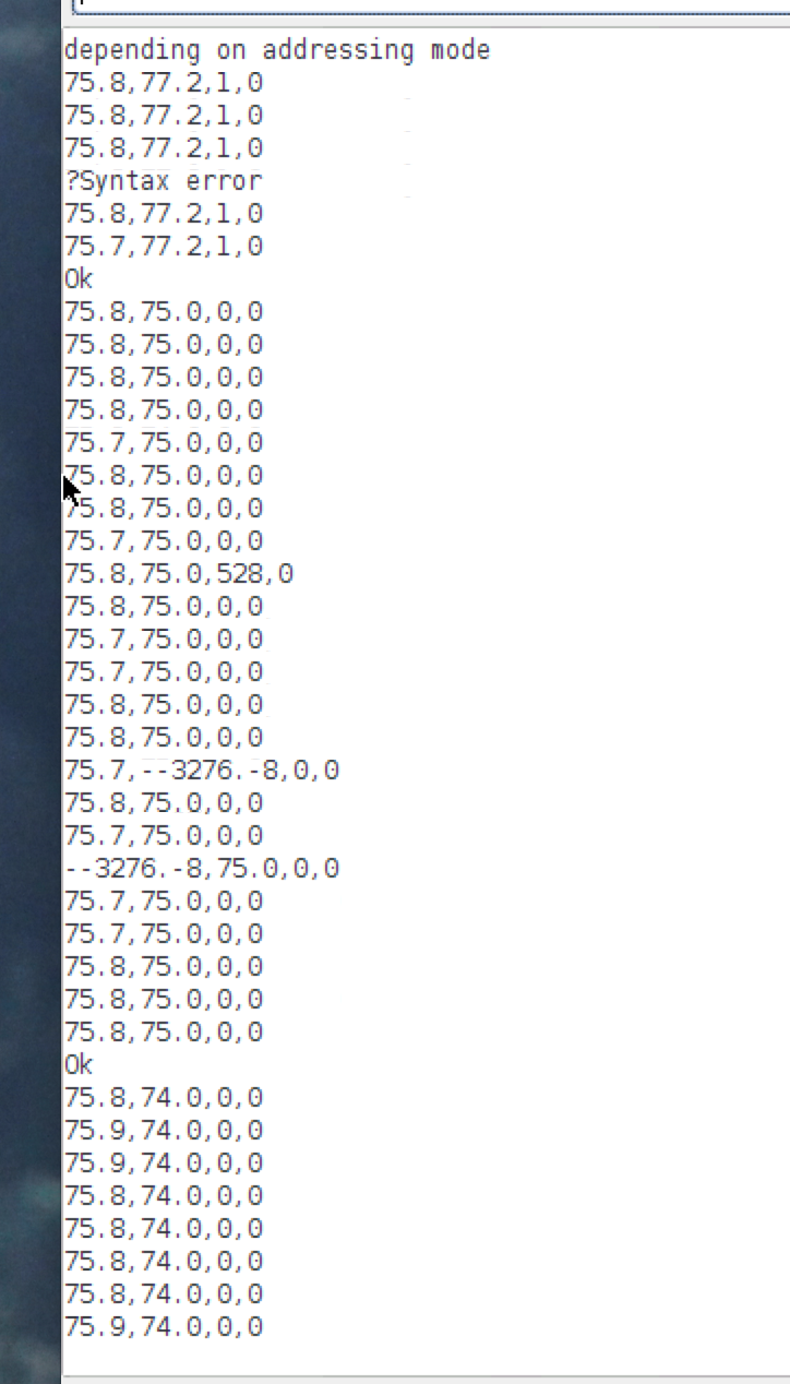
So I think I figured out how to get my 1 wire log working, this is an older screen shot and I'm not sure why there are some errors, but this was the worst case I have seen. It's been running steady for days to the Arduino IDE serial monitor on my RPi 2.

Every 5 seconds it outputs a comma separated line that will get appended to an .csv file, I will push that file to my dropbox maybe once an hour, to keep the network traffic down. In between normal commands can be used to read or write settings just like the regular com.

I have 5 SCTs with 5 Arduinos ready to plug to my RPi to do all the handling. I'm still working on the Python script. Work got a little crazy past few days so I haven't finished what I wan't. Still trying to think what the best way for error checking will be.

Guess I should explain, First number is Current Temperature, Temperature SP, Heating Status, Cooling Status
I will be adding profile, current step and current delay next. If running th mode the string will end there.

Screen Shot 2016-01-27 at 8.32.34 PM.png
 
The following replaced void setup() and void loop()
I was going to skip fixing the temperature decimal place and just deal with it on the other end in Python, but then I figured it still had to look nice. Debating about padding the front few characters with an identifier of some kind, since I will have 5 identical units, would be nice to know what each one is in the event the USB ports get re-arranged.

Code:
See next post for update.
 
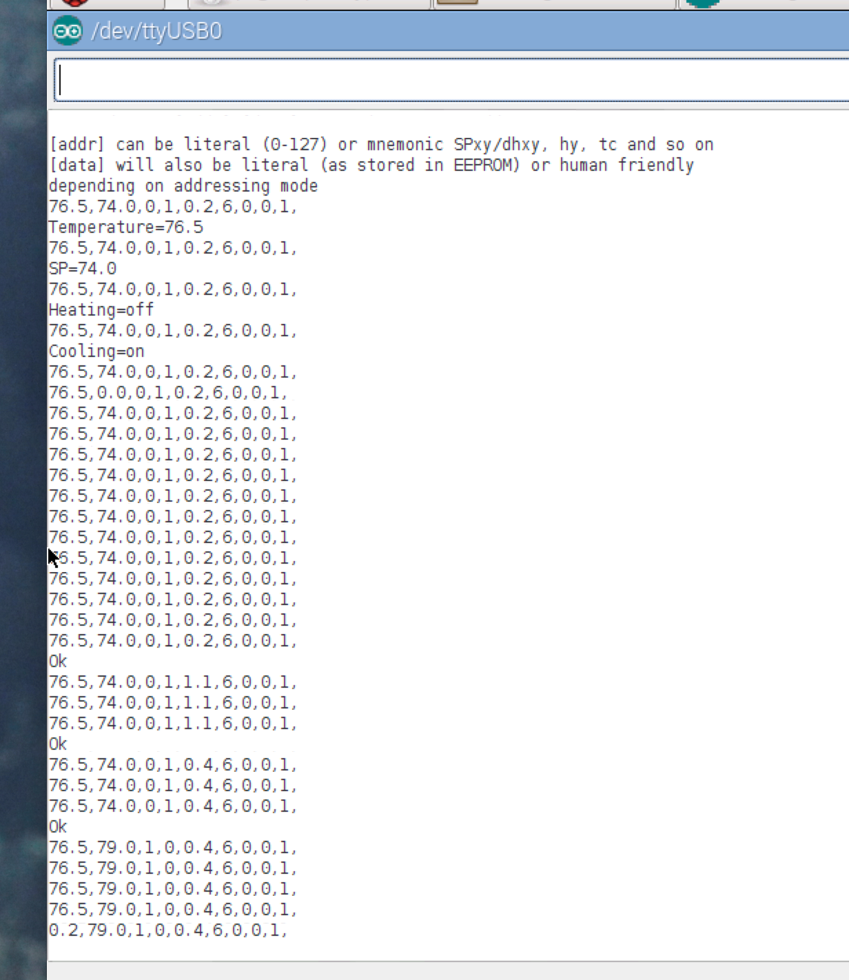
Finished adding the extra parameters to the Log string. Can't seem to create a pull request from Git. Maybe I need to get authorized or something?

Code:
unsigned long startTime = 0;

void setup() {
	Serial.begin(115200);

	delay(2);

	Serial.println("STC-1000+ communication sketch.");
	Serial.println("Copyright 2015 Mats Staffansson");
	Serial.println("");
	Serial.println("Commands: 't' to read temperature");
	Serial.println("          'c' to read state of cooling relay");
	Serial.println("          'h' to read state of heating relay");
	Serial.println("          'r [addr]' to read EEPROM address");
	Serial.println("          'w [addr] [data]' to write EEPROM address");
	Serial.println("");
	Serial.println("[addr] can be literal (0-127) or mnemonic SPxy/dhxy, hy, tc and so on");
	Serial.println("[data] will also be literal (as stored in EEPROM) or human friendly");
	Serial.println("depending on addressing mode");

}

void loop() {
	static char cmd[32], rxchar=' ';
	static unsigned char index=0;
	unsigned long loopTime = abs(millis() - startTime);
	int interval = 5000; 	//Set log ouput interval

		if (loopTime <= interval) {
			if(Serial.available() > 0){
				char c = Serial.read();
				if(!(isBlank(rxchar) && isBlank(c))){
					cmd[index] = c;
					rxchar = c;
					index++;
				}

				if(index>=31 || isEOL(rxchar)){
					cmd[index] = '\0';
					parse_command(cmd);
					index = 0;
					rxchar = ' ';
				}
			}
		}
		else
		{
			int temp;
			int SetPoint;
			int heating;
			int cooling;
			int Hysteresis;
			int Mode;
			int Step;
			int Duration;
			int Ramping;

			read_temp(&temp);
			if(temp < 0){
				temp = -temp;
				Serial.print('-');
			}
			if(temp >= 1000){
				temp /= 10;
				Serial.print(temp);
				Serial.print(",");
			}
			else
			{
			Serial.print(temp/10);
			Serial.print('.');
			Serial.print(temp%10);
			Serial.print(",");
			}
			delay(12);

			read_eeprom(114, &SetPoint);
			if(SetPoint < 0){
				SetPoint = -SetPoint;
				Serial.print('-');
			}
			if(SetPoint >= 1000){
				SetPoint /= 10;
				Serial.print(SetPoint);
				Serial.print(",");
			}
			else
			{
				Serial.print(SetPoint/10);
				Serial.print('.');
				Serial.print(SetPoint%10);
				Serial.print(",");
			}
			delay(12);

			read_heating(&heating);
			Serial.print(heating);
			Serial.print(",");
			delay(12);

			read_cooling(&cooling);
			Serial.print(cooling);
			Serial.print(",");
			delay(12);

			read_eeprom(115, &Hysteresis);
			Serial.print(Hysteresis/10);
			Serial.print('.');
			Serial.print(Hysteresis%10);
			Serial.print(",");
			delay(12);

			read_eeprom(123, &Mode);
			Serial.print(Mode);
			Serial.print(",");
			delay(12);

			read_eeprom(118, &Step);
			Serial.print(Step);
			Serial.print(",");
			delay(12);

			read_eeprom(119, &Duration);
			Serial.print(Duration);
			Serial.print(",");
			delay(12);

			read_eeprom(122, &Ramping);
			Serial.print(Ramping);
			Serial.println(",");
			delay(12);

			startTime = millis();
			delay(12);

		}
	}

Screen Shot 2016-01-29 at 9.07.08 PM.png
 

Latest posts

Back
Top