Stc-1000+

Homebrew Talk - Beer, Wine, Mead, & Cider Brewing Discussion Forum

Help Support Homebrew Talk - Beer, Wine, Mead, & Cider Brewing Discussion Forum:

This site may earn a commission from merchant affiliate links, including eBay, Amazon, and others.
Commendable! Well, I don't really have that much patience. I wish ppl could use this feature a bit more:
mlpelj.png
I agree, and after reading over 2,000 posts I got very accustomed to that feature when I needed to refer back to something stated previously.

All the images that you included are malformed, maybe you can edit the post to fix it?
Fixed

Well, personally I feel like it is complex enough to use as it is. Ideally, I'd like to have completely independent settings, but that is just not feasible. It would be too much work to set up for the user.
Personally I think the only difficult part is getting people to read the supplied instructions, after that it's not complicated at all

Secondly, I find it hard to believe that 500W is not enough to maintain mashout temp. Maybe adding some insulation might help? That is not a bad idea anyway.
The Grainfather is sold as an affordable all-in-one that retails for about half the price of its competitors so you get what you pay for in that regard (which is no doubt why their recipes state switching from Mash to Normal during mash out), no biggy I'll just keep doing that.

Anyway, I'm reluctant to make the kind of change you suggest to the main branch. It seems like a special case.
All good, makes sense if it's only for a specific set up.

I hear ya. Unfortunately, as of now program ends when boil is done. What happens after that is not the concern of the controller (i.e. it can't control cooling).
I'm not saying no to this, as a hop stand probably could be incorporated, and the idea of using negative hop alarms is pretty elegant.
I need to think this over a bit :)
Happy to continue using the timer on my phone if too difficult to implement

This will be very hard to do, as the LUT is compiled into the program HEX file.
Also, generating LUT data from javascript will be hard.
Not impossible, just way more work than I ever think will make it justifiable.
Fair enough, if you want to use your own LUT then you need to skill up!

Well, that looks nice. Unfortunately, HBT forum rules prevents discussion of this.
Thanks for the heads up - removed.
 
*sigh* Looks like I'm running into an issue no one else has mentioned.

...

I've tested with the other versions as well with the same results/errors, and well.. now I'm up against a wall of ignorance. I simply don't know enough of programming/arduino to go further or even search out the right questions.

Help? Frustrating to be the first with this kind of issue that I can find.

Thanks

The errors you get from the compiler does not make a lot of sense to me.
It almost seems like the sketch is corrupt. You say you tested with the other versions, but I'd start with trying to download a fresh sketch.
Next, I'd try to reinstall the Arduino IDE. Maybe even try another computer.
Finally, I know the Leonardo does have its peculiarities. For one thing I think the bootloader is a bit bigger, due to the USB stuff. This may make the sketch to large to fit. I find it odd that it should give compilation errors that make it seem like syntax is bad for that. But you can try selecting an UNO board (you need not have one) and verify (compile) the sketch. If it works then, you can try to remove the not needed HEX data (fahrenheit or celsius depending on what you want to keep).

Good luck!

Personally I think the only difficult part is getting people to read the supplied instructions, after that it's not complicated at all

That, my friend, is the greatest thing I ever heard :) Mind if I use it?
Effing awesome :)

The Grainfather is sold as an affordable all-in-one that retails for about half the price of its competitors so you get what you pay for in that regard (which is no doubt why their recipes state switching from Mash to Normal during mash out), no biggy I'll just keep doing that.

I don't own a grainfather myself and I can't really justify getting one as I already have way too much 'invested' in brewing and am really pretty happy with my setup.
If I hadn't, the grainfather would definately be my system of choice. IMHO they have got a lot of things right (including the price).

Enough about that. I really think you should slap on some insulation. A little goes a long way. I'd make my own, just cut out a piece that fits snugly around it and sow or glue in some velcro straps to be able to put in on/take it off easily. I'd be very surprised if that does not allow you to maintain mash out with 500W.

Happy to continue using the timer on my phone if too difficult to implement

I don't think it is a big thing either, but if/when I get the chance, I'll look into it. Can't make any promises though.

Fair enough, if you want to use your own LUT then you need to skill up!

Kinda, yes. It is not all that hard. With that said, I'm not against supplying additional versions of the firmwares that have other constants compiled in, if there is good reason. The stock NTC used by the grainfather would be a good reason I think.

Cheers!
 
It almost seems like the sketch is corrupt. You say you tested with the other versions, but I'd start with trying to download a fresh sketch.
Next, I'd try to reinstall the Arduino IDE. Maybe even try another computer.

I'd thought of most of these and had, thus, tried several versions of IDE (all fresh installs after reboots), several downloads of the sketches, and 2 computers.

But I think you hit on the problem...

Finally, I know the Leonardo does have its peculiarities. For one thing I think the bootloader is a bit bigger, due to the USB stuff. This may make the sketch to large to fit. I find it odd that it should give compilation errors that make it seem like syntax is bad for that. But you can try selecting an UNO board (you need not have one) and verify (compile) the sketch. If it works then, you can try to remove the not needed HEX data (fahrenheit or celsius depending on what you want to keep).


Code:
Sketch uses 20,252 bytes (70%) of program storage space. Maximum is 28,672 bytes.

This is after I hacked and slashed (lol, and probably broke) the code. Compile had issues with referring to the Celsius data I'd removed, hope I didn't remove too much... And just for giggles, this was the same result with unmodified/raw code:

Code:
Sketch uses 30,562 bytes (106%) of program storage space. Maximum is 28,672 bytes.


Annoying, but easy enough to resolve. You might want to put a warning on github though, that Some versions don't have the storage space needed (probably anything with the ATmega32U4?) Would have stopped me from buying this board, which is quite a bit smaller than I'd imagined (wanting to mount this in my box with the STC so I can just quick-connect a usb cable for changes).

Anyway, thanks for pointing out something I hadn't thought of... sure would have been nice to get a "too big" warning instead of a syntax error.

:mug:

Brian
 
...
Annoying, but easy enough to resolve. You might want to put a warning on github though, that Some versions don't have the storage space needed (probably anything with the ATmega32U4?) Would have stopped me from buying this board, which is quite a bit smaller than I'd imagined (wanting to mount this in my box with the STC so I can just quick-connect a usb cable for changes).

Anyway, thanks for pointing out something I hadn't thought of... sure would have been nice to get a "too big" warning instead of a syntax error.

:mug:

Brian

Cool! Sounds like you're on the right track then!
Yes, you're right. I probably should mention it on the github page. Good thinking. I'll get to it.
You're not the first to have had this issue, but the ppl before you had old Arduinos, with an older bootloader (that was bigger).
I might just look into adding some convenience #defines so it would be easier to leave out one of the HEX files as well.

Cheers!
 
That, my friend, is the greatest thing I ever heard :) Mind if I use it?
Effing awesome :)
Use away mate, I used to work in tech support and went to a lot of trouble setting up FAQs for common issues, what found was the hgher the quality of your FAQs the lower the percentage of intelligent callers you would get...

Enough about that. I really think you should slap on some insulation. A little goes a long way. I'd make my own, just cut out a piece that fits snugly around it and sow or glue in some velcro straps to be able to put in on/take it off easily. I'd be very surprised if that does not allow you to maintain mash out with 500W.
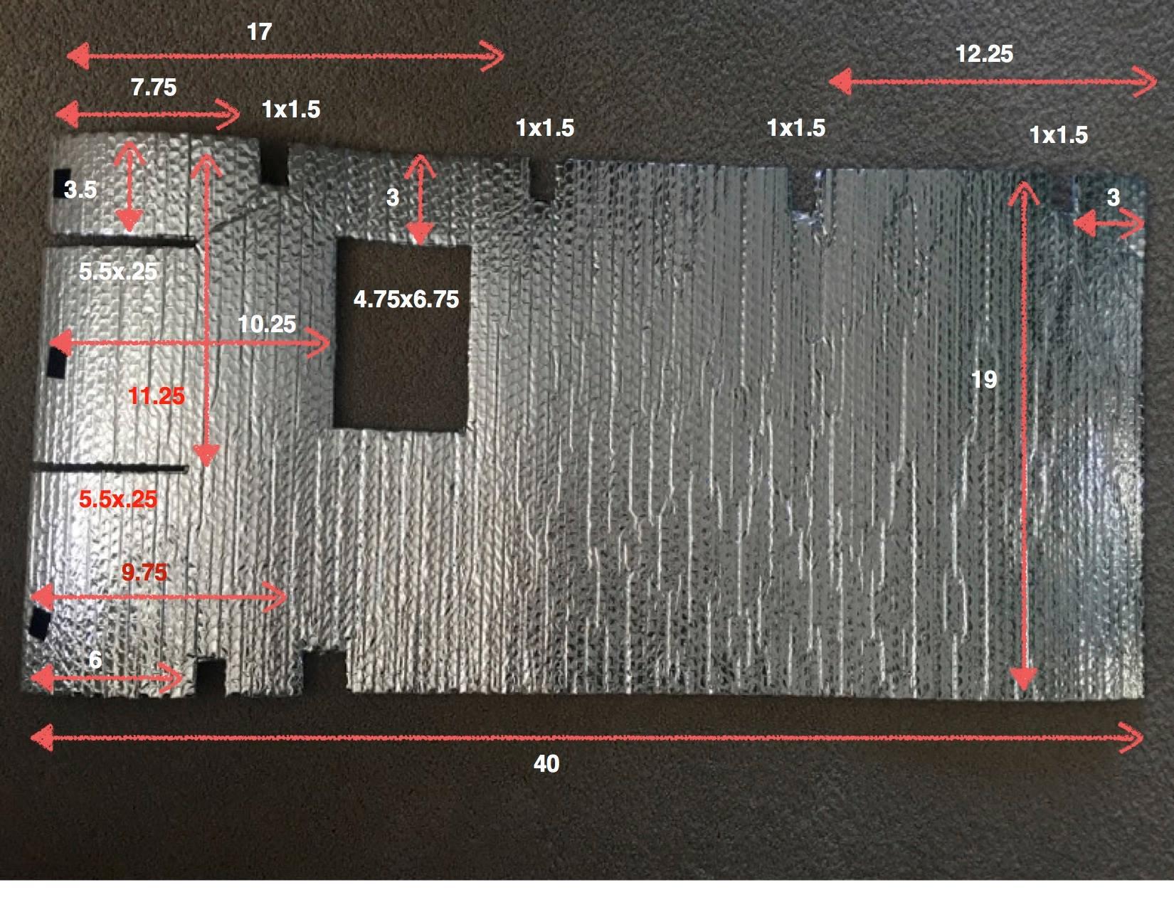
SOLD! A simple Google search of "Grainfather insulation" even gave me the basic template to make one:
cNvFJQB.jpg

So I've ordered the materials online and will post the pics when it's done.

I don't think it is a big thing either, but if/when I get the chance, I'll look into it. Can't make any promises though.
All good mate I know you have a young family and work commitments and you do this in your copious free time that's left after that :)

Kinda, yes. It is not all that hard. With that said, I'm not against supplying additional versions of the firmwares that have other constants compiled in, if there is good reason. The stock NTC used by the grainfather would be a good reason I think.
I made two 32 step lookup tables for the Grainfather NTC which I'm happy to share:

This one is as close to full range as could do in a home environment (3 degree steps from freezing to as close to boiling as can get in 32 steps)

Code:
0.0 28160
3.0 24560
6.0 21770
9.0 19210
12.0    17020
15.0    15000
18.0    13330
21.0    11890
24.0    10590
27.0    9440.0
30.0    8470.0
33.0    7600.0
36.0    6780.0
39.0    6090.0
42.0    5490.0
45.0    4960.0
48.0    4480.0
51.0    4050.0
54.0    3680.0
57.0    3340.0
60.0    3040.0
63.0    2770.0
66.0    2530.0
69.0    2310.0
72.0    2120.0
75.0    1930.0
78.0    1770.0
81.0    1630.0
84.0    1535.0
87.0    1420.0
90.0    1310.0
93.0    1210.0

This one is 1.5 degree steps within the usable range for mashing as I figured it would be more accurate and the outside ranges are of no consequence anyway (this is the one I use and I have tested it with the Thermopen and it is pretty spot on within the workable range).

Code:
34.5    7140.0
36.0    6780.0
37.5    6420.0
39.0    6090.0
40.5    5780.0
42.0    5490.0
43.5    5220.0
45.0    4960.0
46.5    4710.0
48.0    4480.0
49.5    4265.0
51.0    4050.0
52.5    3860.0
54.0    3680.0
55.5    3520.0
57.0    3340.0
58.5    3190.0
60.0    3040.0
61.5    2900.0
63.0	2770.0
64.5    2650.0
66.0    2530.0
67.5    2420.0
69.0    2310.0
70.5    2205.0
72.0    2120.0
73.5    2020.0
75.0    1930.0
76.5    1840.0
78.0    1770.0
79.5    1750.0
81.0    1630.0

Of course you could always add "33.0 7600.0" to the start of this one and remove "81.0 1630.0" from the bottom if you wanted to, but this one works for me.

Cheers,

Kal
 
@mattrox: Looks like you got lucky and got one of the few with very little solder in the through holes for the programming header.
It's still coated in silicone though, so clean (in and around) the holes with a toothpick.
 
@mattrox: Looks like you got lucky and got one of the few with very little solder in the through holes for the programming header.
It's still coated in silicone though, so clean (in and around) the holes with a toothpick.

There is no solder at all in the holes. A change in manufacturing processes?
 
I don't think so. I've done approx 200 of them myself and of these a handfull or so have had very little or no solder in the holes.
Just a manufacturing fluke.
 
I don't think so. I've done approx 200 of them myself and of these a handfull or so have had very little or no solder in the holes.
Just a manufacturing fluke.

Ok cool.

Thank you for all your work on this. I'm turning mine into dual probe. What you have done is genius.
 
I have flashed it with the 2 probe version and started work on converting it for 2 probe.

Most of the components are still on their way. But I got impatient.

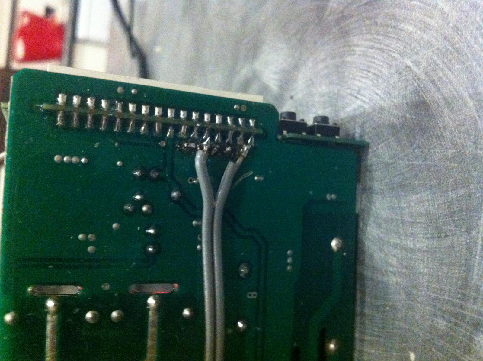
The bare holes meant it was easy to just use the dupont wires to flash..... Then I decided to solder them in place.

View attachment 1446196478906.jpg
 
Hi and thanks!
There should be no problem leaving the Arduino connected.
I would suggest using a diode on the 5v-Vdd, to avoid the arduino being powered from the STC. But, it should be fine without it as well.
If you don't add the diode, then you should avoid plugging in the usb while mains powered.

Any old diode? Just don't want to add something that might release smoke later.:mug:
 
I haven't really tried this myself, but I think pretty much any diode would work. If you are looking to buy some, then a schottky diode would be preferrable, something like BAT85 or BAT54 would probably be good.
 
I haven't really tried this myself, but I think pretty much any diode would work. If you are looking to buy some, then a schottky diode would be preferrable, something like BAT85 or BAT54 would probably be good.

I was thinking of building in a nano into the project box so there is just a USB connection to link to the computer for future flashings. It seemed a good solution, rather than wiring in some sort of plug to link up to the Uno.

Thanks for your advice.
 
I was thinking of building in a nano into the project box so there is just a USB connection to link to the computer for future flashings. It seemed a good solution, rather than wiring in some sort of plug to link up to the Uno.

Thanks for your advice.

That's exactly what I did with mine and it's working very well. I just popped in a diode I had hanging around and it seems to work well.

Good luck with it.

Demig
 
That's exactly what I did with mine and it's working very well. I just popped in a diode I had hanging around and it seems to work well.

Good luck with it.

Demig

Thanks for that info. :)

How did you mount the Nano in the project box?
 
Thanks for that info. :)

How did you mount the Nano in the project box?

Nothing fancy just a good blob of hot melt glue on the bottom. Cut the hole for the usb socket, plugged in a usb wire on the outside of the box and then used that to hold it while the glue set. Works a treat.

If I get a chance I'll grab a picture.

Demig
 
Nothing fancy just a good blob of hot melt glue on the bottom. Cut the hole for the usb socket, plugged in a usb wire on the outside of the box and then used that to hold it while the glue set. Works a treat.

If I get a chance I'll grab a picture.

Demig

Cheers. I'd be interested to see it.
 
Brewday yesterday with STC-1000+ OVBCS and STC-1000+ Dual Probe

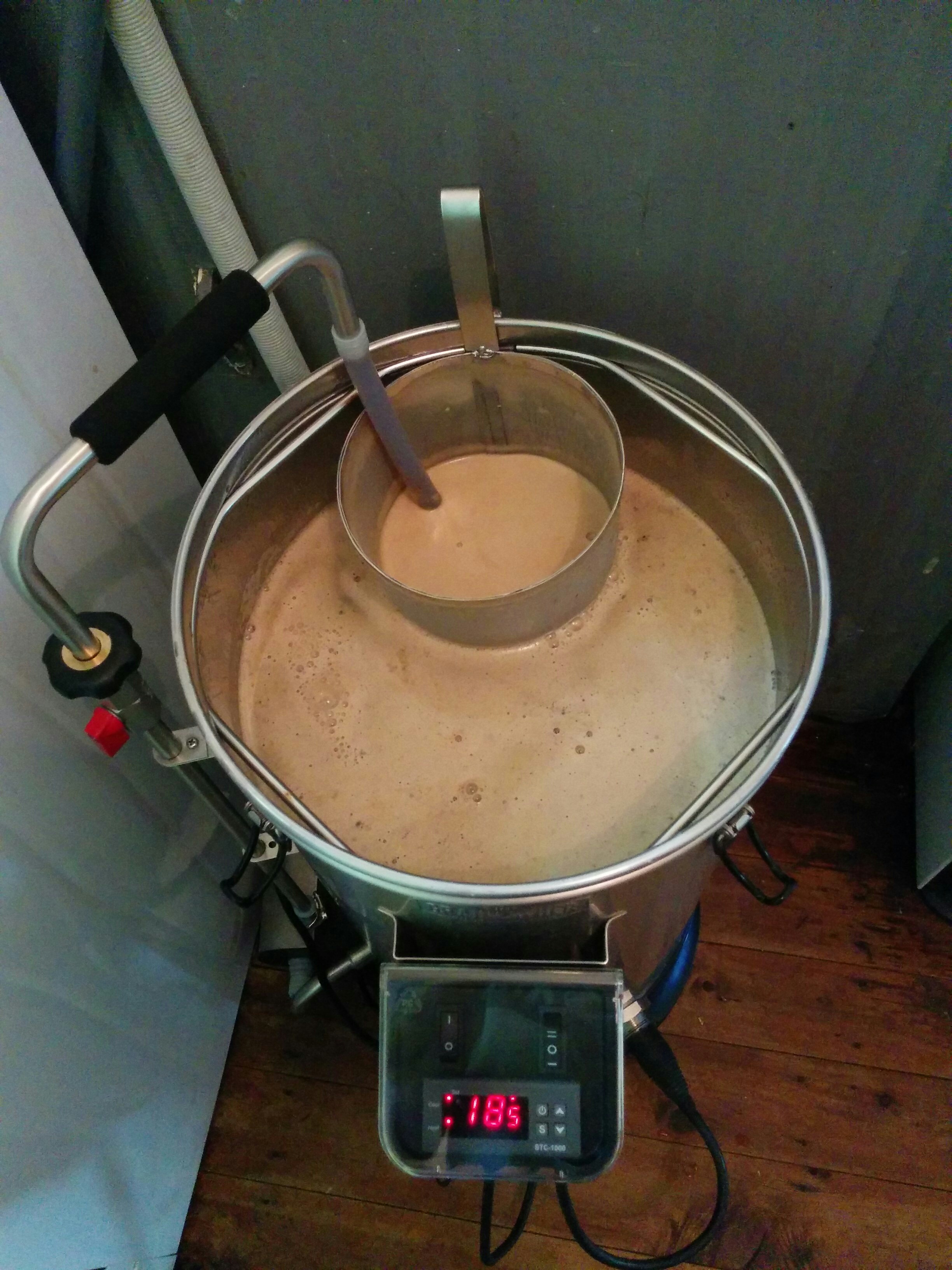
Loving the automated pump control! Both heating and cooling relays active (2200w & 500w respectively), output set to -200 until hot break kicks in at 200*F then output is -150 with heating period interval set to 8.0 (so 500w element stays on and 2200w element cycles on for 4 seconds then off for 4 seconds)

2015-11-01-112135-66308.jpg


Nice rolling boil using only the heater relay (2200w element), output set to 100 (1000m above sea level so lower boiling temperature)

2015-11-01-113820-66309.jpg


Dual probe using 3.5mm stereo fitting (taped one is probe 2)

2015-10-30-161014-66310.jpg


Fermentation fridge (probe 2 in 100mm thermowell in lid that reads fermenter air temp, probe 1 in 9" thermowell to read liquid temp)

2015-11-01-152438-66311.jpg


Today all is happily bubbling away and temps are sitting stable 21 hours into 120 hours of step 1

Cheers,

Kal
 
Argh... Fair warning through my headaches, the ATmega32U4 chip is a PITA. Since the USB controller is on the chip you lose space, AND it doesn't play well with the sketch. By "doesn't play well" I mean that the USB connection will connect, then drop about 5~8 seconds later Most of the time. Sometimes it works fine (rarely).. I managed to get my STC loaded but was looking to mount the Arduino in my housing for quick/simple USB connectivity and it's not reliable enough for that.

To sort of "reset" everything, you have to "rest"by grounding the rest pin, then flash a blank/simple sketch (whatever pops up at first with IDE 1.6.5) by timing everything just right. I start the upload roughly 6~7 seconds before connecting the USB. Time it right and everything's back to normal. Load the STC sketch and it's luck of the draw on connectivity again.

Maybe a more knowledgeable Arduino person could figure it out (hey, anyone wanna trade?), but for anyone out there looking to do this for the first time, avoid the ATmega32U4 chip based boards (Pro Mini, Teensy, etc...) It's just not worth the headache.
 
@BrianM: Sounds like you've had more problems that you should have. I've not heard of shaky connection with those before. But still. Fair point. The Arduino Nano clones are dirt cheap. I buy them (and the pro minis) by the dozen. So cheap, it is always good to have a few at hand, for various projects.
So, grab yourself a Nano and don't look back :)
 
Brewday yesterday with STC-1000+ OVBCS and STC-1000+ Dual Probe

Loving the automated pump control! Both heating and cooling relays active (2200w & 500w respectively), output set to -200 until hot break kicks in at 200*F then output is -150 with heating period interval set to 8.0 (so 500w element stays on and 2200w element cycles on for 4 seconds then off for 4 seconds)

2015-11-01-112135-66308.jpg


Nice rolling boil using only the heater relay (2200w element), output set to 100 (1000m above sea level so lower boiling temperature)

2015-11-01-113820-66309.jpg


Dual probe using 3.5mm stereo fitting (taped one is probe 2)

2015-10-30-161014-66310.jpg


Fermentation fridge (probe 2 in 100mm thermowell in lid that reads fermenter air temp, probe 1 in 9" thermowell to read liquid temp)

2015-11-01-152438-66311.jpg


Today all is happily bubbling away and temps are sitting stable 21 hours into 120 hours of step 1

Cheers,

Kal

Looks awesome!
 
Looks awesome!

Thanks, but all the credit goes to alphaomega!

I originally heard about the STC-1000+ in a dedicated Grainfather forum and bought a pre-flashed unit, but "you walk a mile - you see a mile", so then the modification frenzy began, and is still ongoing (insulation jacket is the next mod).

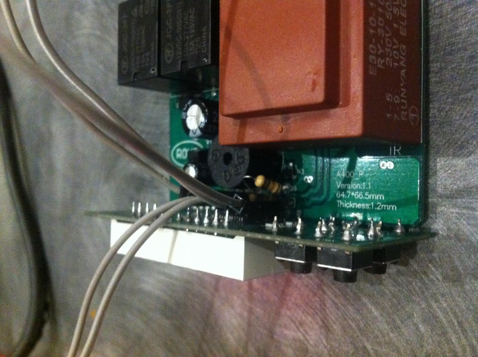
Ironically for my fermentation fridge I initially tried to upgrade to a KegKing programmable thermo controller but the supplier sent me an STC-1000 in a case instead. After finding out about the STC-1000+ a few weeks later I opened it up and discovered it was an A400_P so I flashed it and converted it into a dual probe (KegKing don't sell those).

This is a great project and I'm glad I discovered it even if it did have to read over 2,000 posts to get up to speed (better late than never).
 
@alphaomega I was looking through the data logging via the arduino.... since I plan on keeping it attached. Then my mind wandered.....

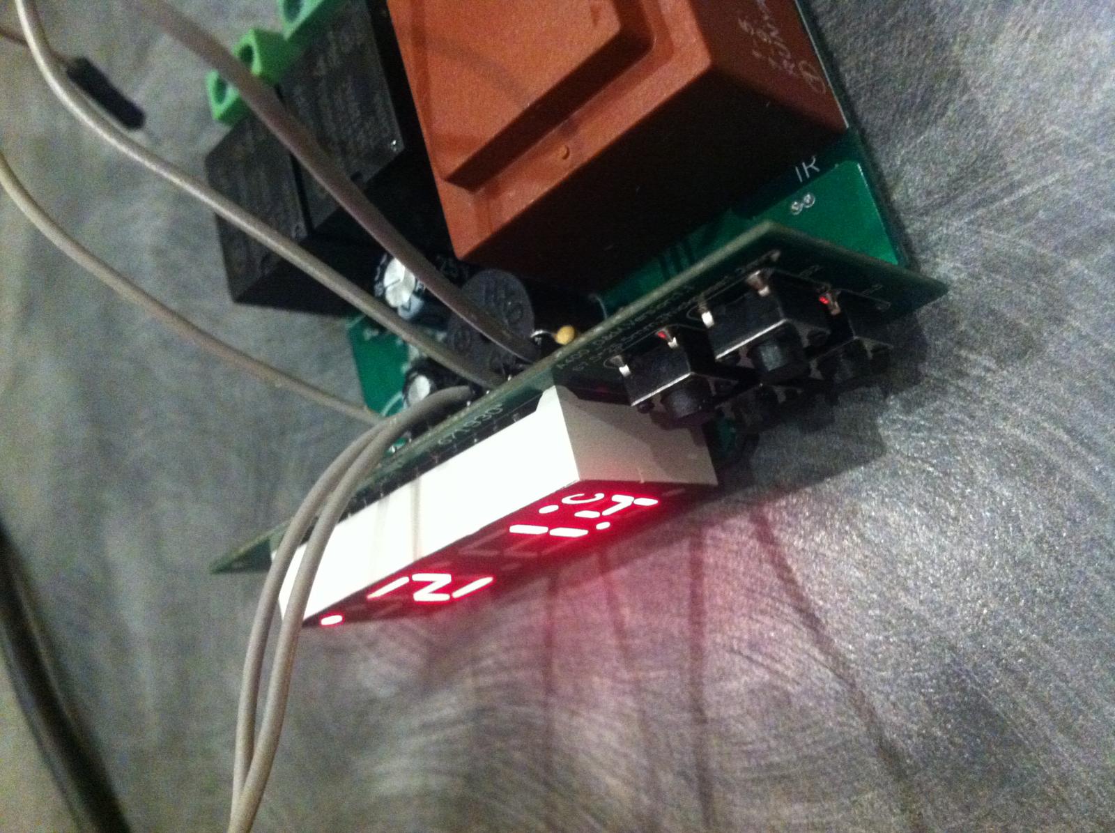
Now, I noticed you had the header for the display numbered and 8 was vcc, 9 heating relay and 10 cooling relay. Could I hook up a dual colour LED to these contact points to display red/blue? Common to the vcc and red to 9 and blue to 10?

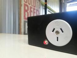
I wanted this, as I have a 240V light come on when the sockets had power being delivered. Let's say a relay does something stupid and is supplying power when it shouldn't ... or is not supplying power when it should, the LED would serve as an immediate visual double check that everything is ok (or not)

This will supply me 5V. But the LEDs are like 3ish V, is this a problem? Should I chuck in a resistor on the vcc to common pin connection?

post-26873-14451232043176_thumb.jpg


post-26873-14451231909595_thumb.jpg
 
@mattrox: Regarding logging, you're on your own. The stuff I have on github is pretty much proof of concept stuff, not 'finished', but may be a good starting point to do your own hacking.
You probably could hook up LED's that way, but I think you'll need a common cathode one (common to ground). You always need a current limiting resistor for LEDs.

Yes, the logging is more of a long term thing I'll look into.

I'm really just getting my head back into basic electronics. I've forgotten most of what I used to know, and even that was pretty entry-level.

I figured I have already damaged this STC unit with that stupid 10 ohm SMD chip escapade that I might as well experiment with this one. I'll have a play and see what happens.

Oh, the eBay seller will send the correct part now. Anyone need 10 ohm SMD resistors? Lol
 
Five days in, and we've reached the next step - gentle ramp up from 68*F to 73*F over 24 hours:

2015-11-06-161449-66345.jpg


This brew is going to be our drinks for our staff Xmas party, I'll have one for you Mats!
 
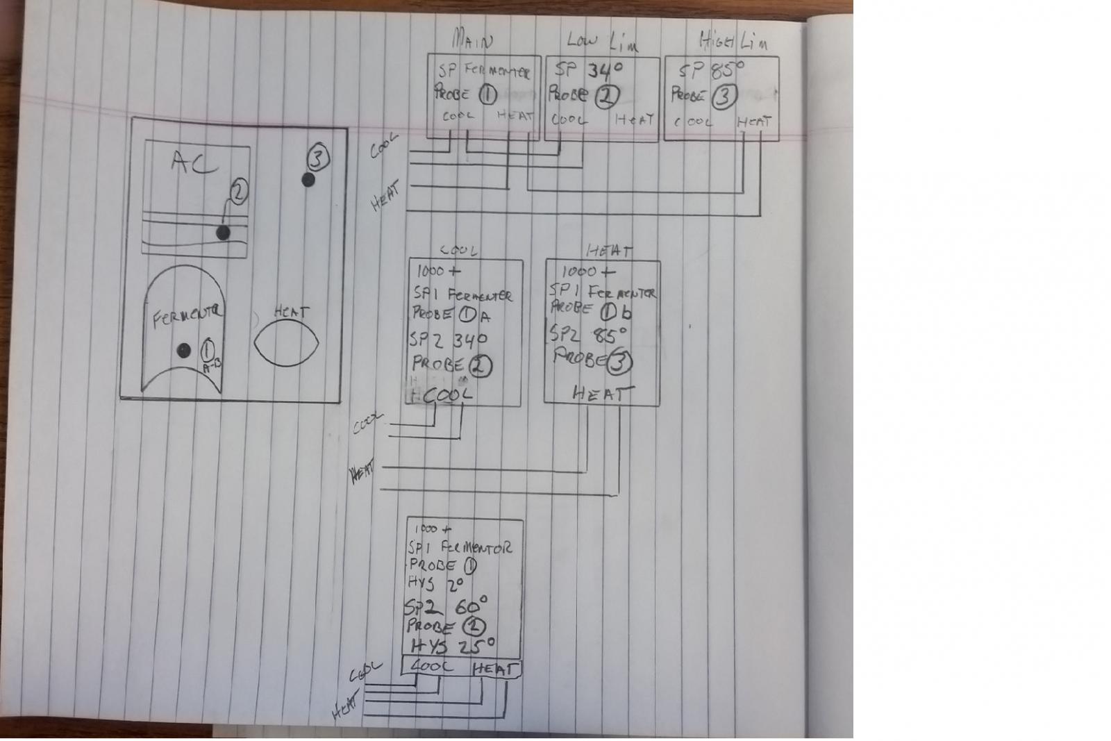
alphaomega, I'm building a fermentation chamber using a window AC. Using the 1000+ with dual probe I see this working real well. Place probe 1 into the fermenter and the second probe is placed in between the first row of fins on the AC. Cooling output heats the AC temp probe, probably using self regulating heat wire. Setting SP 1 to fermentation temp and SP 2 just above freezing, 34* to keep the coils from freezing over. I.E. Coolbot controller. I can also do the same using 2 unmodified STCs and series the cool output to the AC.

Then I started thinking about the heating side.... I run a small portable heater. With the mass of the fermenter if the heat is on trying to heat the 5-10 gal the chamber could get way to hot before the first probe in fermenter gets to set point. I need a high limit of chamber temperature. Now for the question, the STC hysteresis is limited to .3-10c*. If this limit could be opened up to say 25f* I could do the following... Probe 1 and SP 1 still fermenter temp. Probe 2 in AC fins, if ac off the probe would read close to chamber temp. SP for probe 2 would be 60* with the hysteresis set to 25*. So the probe 2 would turn cooling off at 35* to keep AC coils from freezing and turn heater off at 85* to keep the chamber from over heating.

This can be done with 3 STC 1000. 2 STC 1000+ dual probe, 1 STC for cooling, one for heating. But can it be done with 1 STC 1000+ dual probe? Can the hysteresis limit be raised?

.

1a.jpg
 
Can the STC1000+ handle the amperage draw from the AC unit you're planning on using? I seems that most window AC units draw more than the STC can safely handle.
 
@alphaomega

If the look up table were in uneven increments, would that effect the calculations for the STC?

I was thinking, to make best use of the 32 data points, closer values in the 10-30 deg C range would be useful. This is something I'd like to toy with.

My thinking is that at very low temperatures the gradient of the curve is steep and linear modelling between 2 points looks a close approximation. Likewise at higher temperatures, it appears that the curve will allow data points with are further apart. The rate of change of the curve is greatest below 25 deg C in the temperature range of interest in fermentation.

I'll have a look at some curves.

It might not make much difference, given the thermistor looks to be ~+/-0.5 deg C and the model may be within this anyway.
 
alphaomega, I'm building a fermentation chamber using a window AC. Using the 1000+ with dual probe I see this working real well. Place probe 1 into the fermenter and the second probe is placed in between the first row of fins on the AC. Cooling output heats the AC temp probe, probably using self regulating heat wire. Setting SP 1 to fermentation temp and SP 2 just above freezing, 34* to keep the coils from freezing over. I.E. Coolbot controller. I can also do the same using 2 unmodified STCs and series the cool output to the AC.

Then I started thinking about the heating side.... I run a small portable heater. With the mass of the fermenter if the heat is on trying to heat the 5-10 gal the chamber could get way to hot before the first probe in fermenter gets to set point. I need a high limit of chamber temperature. Now for the question, the STC hysteresis is limited to .3-10c*. If this limit could be opened up to say 25f* I could do the following... Probe 1 and SP 1 still fermenter temp. Probe 2 in AC fins, if ac off the probe would read close to chamber temp. SP for probe 2 would be 60* with the hysteresis set to 25*. So the probe 2 would turn cooling off at 35* to keep AC coils from freezing and turn heater off at 85* to keep the chamber from over heating.

This can be done with 3 STC 1000. 2 STC 1000+ dual probe, 1 STC for cooling, one for heating. But can it be done with 1 STC 1000+ dual probe? Can the hysteresis limit be raised?

.

Firstly, yes the hysteresis limits could be changed. But, it would still be dependent on on setpoint, so you'd be limited to only 60'ish in this case.
I do think that the easy solution would be to use an extra STC-1000 for the AC to stop it from frosting up.
Look into getting a lower power heater. You do not need to raise temps quickly. In an enclosed space, a little heat goes a long way.
Also, what @stpug said, make sure the AC draws less than 15 amps.

@alphaomega

If the look up table were in uneven increments, would that effect the calculations for the STC?

I was thinking, to make best use of the 32 data points, closer values in the 10-30 deg C range would be useful. This is something I'd like to toy with.

My thinking is that at very low temperatures the gradient of the curve is steep and linear modelling between 2 points looks a close approximation. Likewise at higher temperatures, it appears that the curve will allow data points with are further apart. The rate of change of the curve is greatest below 25 deg C in the temperature range of interest in fermentation.

I'll have a look at some curves.

It might not make much difference, given the thermistor looks to be ~+/-0.5 deg C and the model may be within this anyway.

You are free to play around all you want! So, please do so if you like :)
But I really don't think there is much room for improvement here.
First off, we are really constrained by code space, so the implementation needs to be really efficient (not fast, but few instructions). This limits the freedom you have to get creative.
Secondly, I'm sure you have had a look at the characteristics of the NTC. Around 25C the curve is pretty linear and accuracy is pretty good. This already works for us. As we deviate further from 25C, yes, the curve will be more linear again, but by that point, accuracy is pretty much shot.
The 0.5C accuracy of the probe, I think is mainly manufacturing tolerances and will mostly be static error. You also have the 10k resistor for the voltage divider, that introduces a possible error.
Bottom line is, I don't think the current implementation is the bottleneck.

What might be done, is some better analysis of the lookup points around the 'knees' of the curve. There might be one or two lookup points, that could give better overall linearisation if they were 'nudged'. But these would probably just change 0.1 deg, and you'd need to make sure this improves the linearisation, and I'm not sure it would. Even this would be such a marginal improvement and probably outside the range of fermentation.

You'd probably be better off trimming the 10k resistor, and procuring a probe with low statical error if you want better accuracy.

But still, do play around! Who knows, right :) More eyes on the code never hurt!
 
Firstly, yes the hysteresis limits could be changed. But, it would still be dependent on on setpoint, so you'd be limited to only 60'ish in this case.
I do think that the easy solution would be to use an extra STC-1000 for the AC to stop it from frosting up.
Look into getting a lower power heater. You do not need to raise temps quickly. In an enclosed space, a little heat goes a long way.
Also, what @stpug said, make sure the AC draws less than 15 amps.


You are free to play around all you want! So, please do so if you like :)
But I really don't think there is much room for improvement here.
First off, we are really constrained by code space, so the implementation needs to be really efficient (not fast, but few instructions). This limits the freedom you have to get creative.
Secondly, I'm sure you have had a look at the characteristics of the NTC. Around 25C the curve is pretty linear and accuracy is pretty good. This already works for us. As we deviate further from 25C, yes, the curve will be more linear again, but by that point, accuracy is pretty much shot.
The 0.5C accuracy of the probe, I think is mainly manufacturing tolerances and will mostly be static error. You also have the 10k resistor for the voltage divider, that introduces a possible error.
Bottom line is, I don't think the current implementation is the bottleneck.

What might be done, is some better analysis of the lookup points around the 'knees' of the curve. There might be one or two lookup points, that could give better overall linearisation if they were 'nudged'. But these would probably just change 0.1 deg, and you'd need to make sure this improves the linearisation, and I'm not sure it would. Even this would be such a marginal improvement and probably outside the range of fermentation.

You'd probably be better off trimming the 10k resistor, and procuring a probe with low statical error if you want better accuracy.

But still, do play around! Who knows, right :) More eyes on the code never hurt!

The reason I asked was redfish sensors has data for 1 degree increments from -40 to 125 C.

They provide min med and max data for a 10k 3435 1% resistors. Ok they are SMD type but the specs are the same. So I used their median data. I chose the 15 and 20 degree data for the linear model then used the resistance data for 16, 17, 18 and 19 to calculate a temperature. It was 0.1 deg C out to 3 sig figs.

I had a hunch that any modelling error would be with the bounds of the expected error of the thermistor.

It seems industry standard to use 5 degree intervals. They aren't going to compromise accuracy too much are they?

Incidentally, the data for your look up table lies between the median and max of the redfish sensor data.

I'll have a close look at in between values but I don't think there will be anything ground breaking. Worth a look.

I have 7 thermistors that I can check the resistance at 0 and 100 C easily. Out of interest I want to compare to the LUT and the redfish data.

A difference of 1 deg might be the difference between yeast flocculating and might be important if fermenting at the lower end of the yeast's temperature range. But it looks like this is not too much of a concern.
 
Incidentally I found a 0.1% 10K resistor but it is $6.08 AUD ea. About 1/3 the cost of the STC in the 1st place. But without a thermistor to match, it's fairly pointless. And looking through readily available Spec Sheets I have not seen a thermistor that is rated less than 1%.
 
@mattrox : If you want to mess with this stuff, then have a look at the NTC LUT generator that I used to create the look up table (if you haven't already).
It uses an external project http://thermistor.sourceforge.net/ to calculate the Steinhart-Hart coefficients from a table of temperature-resistance data.
From this, I use my own program (lut.c) to calculate the temperature at each of the look up points and generate the lookup table (the data I used is here).

This makes it incredibly easy to use other data sets as input data.
10k beta 3435(25/85C) NTC's should have the same characteristics, regardless of being SMD or not. Note though that you need to be vary of what temperature range the beta value actually is calculated for.

I just used google to find a table of temperature-resistance data to use for the probe as input. I can't be sure this is the best dataset for the sensors for the STC-1000. But I would think it should be pretty close. And it would be hard to verify, unless you tested probably more than a handful sensors, using a well calibrated resistance meter and highly accurate thermometer, in a controlled environment (like a heated water bath).

It seems industry standard to use 5 degree intervals. They aren't going to compromise accuracy too much are they?
No, I don't think so either. I think that is pretty sane.

A difference of 1 deg might be the difference between yeast flocculating and might be important if fermenting at the lower end of the yeast's temperature range. But it looks like this is not too much of a concern.
That is why you can calibrate. You should calibrate around your working point. That is, if you typically ferment at around say 10C for a lager to 18C for an ale, then calibrate at 14C with a known good thermometer. The resulting error around 14C (say +-10C) should be negligible.
 
I have found this 10K 3977 0.75% NTC with data. $4.23 AUD on Ebay http://www.vishay.com/docs/29051/ntclesb.pdf

and this Betatherm 10K NTC 3976 NTC with data which claims 0.2 deg C between 0 and 70 Deg for $16.09 AUD
http://www.farnell.com/datasheets/69441.pdf

and this similar unit.
http://www.farnell.com/datasheets/1786656.pdf

The 1st one is more economical, but needs hacking to make suitable for brewery use, but easily do-able.

Given both brands have data, perhaps it is worthwhile to investigate, but the gains in precision do come at a cost. It's probably not worth it economically, but out of interest's sake it might be.
 
@mattrox: Well, I'm not really gonna try to talk you down if you want to try it. But personally, just calibrating is good enough for me.
The STC-1000 is what it is. It is good value for money, pretty well designed, but low cost. All the parts pretty much are to the same standard.

I guess, I just don't see this doing very much, it's still an NTC. Even with slightly better tolerances, the non-linearity does not go away. And accuracy still will be mostly dependent on calibration.
If you really want it to be as accurate as can be, I still think you'd have better luck just trying to calibrate/balance your NTC/resistor combo.

But I might be wrong.

You are not wrong.

I was more looking at this as a learning exercise.

Getting the STC to this stage was fun but once it is built the fun is over. I don't want the fun to end. lol
 
You are not wrong.

I was more looking at this as a learning exercise.

Getting the STC to this stage was fun but once it is built the fun is over. I don't want the fun to end. lol

Not sure if this is of interest to you, but I made these two LUTs for the standard STC-1000 NTC while I was creating the LUTs for the Grainfather NTC:

This one is 0*C - 93*C with 3*C increments:

Code:
0.0 27340
3.0 23800
6.0 21200
9.0 18750
12.0    16600
15.0    14700
18.0    13100
21.0    11600
24.0    10400
27.0    9300.0
30.0    8300.0
33.0    7500.0
36.0    6700.0
39.0    6000.0
42.0    5450.0
45.0    4900.0
48.0    4450.0
51.0    4040.0
54.0    3660.0
57.0    3330.0
60.0    3015.0
63.0    2745.0
66.0    2505.0
69.0    2290.0
72.0    2100.0
75.0    1925.0
78.0    1770.0
81.0    1625.0
84.0    1500.0
87.0    1380.0
90.0    1280.0
93.0    1180.0

This one is 6*C to 37*C with 1*C increments:

Code:
6.0 21200
7.0 20300
8.0 19500
9.0 18750
10.0    18000
11.0    17300
12.0    16600
13.0    15900
14.0    15300
15.0    14700
16.0    14150
17.0    13600
18.0    13100
19.0    12600
20.0    12100
21.0    11600
22.0    11200
23.0    10800
24.0    10400
25.0    10000
26.0    9600.0
27.0    9300.0
28.0    9000.0
29.0    8650.0
30.0    8300.0
31.0    8050.0
32.0    7750.0
33.0    7500.0
34.0    7200.0
35.0    6950.0
36.0    6700.0
37.0    6500.0

I use the second one with my dual probe STC-1000+ on my fermenation fridge and tested it within those temps using water and a Thermopen.

Cheers,

Kal
 

Latest posts

Back
Top