• Please visit and share your knowledge at our sister communities:
  • If you have not, please join our official Homebrewing Facebook Group!

    Homebrewing Facebook Group

Stc-1000+

Homebrew Talk

Help Support Homebrew Talk:

This site may earn a commission from merchant affiliate links, including eBay, Amazon, and others.
Alpha, I just built one of your cheap programmers and the instructions were spot on. It worked great the first try.

Also, I just grabbed the latest work commit (12a0a2873de5f986adb87781fc02021d94abcf8e) and dropped it on an STC.

I haven't connected a second probe yet. I'm planning to do that soon, but I can't do any logging until my BrewPi is available (fermenting an Oktoberfest right now). I may just set up another BrewPi for logging using an old PC.

At any rate, once I can log I will test 1.06 out and run the second probe with a few different hysteresis settings to see what works best.

In the mean time, a few questions and suggestions:

1) Can you copy the second probe hardware install instructions into the docs?

2) Can the second probe be connected at the solder pad next to the existing temp probe connection and share a common leg?

3) Even though I don't have a second probe installed, I see a temperature on the display that is offset (lower) than the actual temperature and increases as the primary sensor measure increases. Is this expected?

4) I do not get an alarm with pb=1, again, with no secondary probe hardware installed.

5) I like the OFF functionality.

6) Can you go into more detail about how the unit behaves with the second probe installed? Maybe run through some scenarios?

Thanks! Can't believe how much more you've wrung out of this hardware.
 
Any room for an alarm setting? For example if you are using a fermentation chamber to first chill down to pitching temperature an alarm to let you know so you can pitch yeast would be useful.
 
Alpha, I just built one of your cheap programmers and the instructions were spot on. It worked great the first try.

Also, I just grabbed the latest work commit (12a0a2873de5f986adb87781fc02021d94abcf8e) and dropped it on an STC.

I haven't connected a second probe yet. I'm planning to do that soon, but I can't do any logging until my BrewPi is available (fermenting an Oktoberfest right now). I may just set up another BrewPi for logging using an old PC.

At any rate, once I can log I will test 1.06 out and run the second probe with a few different hysteresis settings to see what works best.

In the mean time, a few questions and suggestions:

1) Can you copy the second probe hardware install instructions into the docs?

2) Can the second probe be connected at the solder pad next to the existing temp probe connection and share a common leg?

3) Even though I don't have a second probe installed, I see a temperature on the display that is offset (lower) than the actual temperature and increases as the primary sensor measure increases. Is this expected?

4) I do not get an alarm with pb=1, again, with no secondary probe hardware installed.

5) I like the OFF functionality.

6) Can you go into more detail about how the unit behaves with the second probe installed? Maybe run through some scenarios?

Thanks! Can't believe how much more you've wrung out of this hardware.

Thanks! Nice to hear!

1. Thanks you! I completely forgot about that! That is what happens when you get 'homeblind' as we say in Sweden :) I'll fix it!

2. Yes absolutely! I exchange the 2 pole terminal for a 3 pole on, and solder in the missing 10k 0603 smd resistor (which is very fiddly work). The middle pole is the shared one.

3. I haven't actually tried, but it certainly possible. My guess is second A/D channel is floating without the resistor and probe, and the internal charge/store/sample capacitor therefore retains some charge from ch1.

4. You probably will with the resistor in place. Let me know otherwise.

5. Thanks! I also think it became a whole lot better this way :)

6. Yeah. Lets make it easy. Lets say SP is 70.0, hy 1.0 and hy2 10.0. Now, in order for cooling to turn on, t1 must be at least SP, and t2 SP-(hy2 * 0.5), that is 70.0-(10.0 * 0.5) = 65.0. Cooling turns off when either t1 is less than SP-hy (69.5), or t2 is less than SP-hy2 (60.0). Same thing with heating only signs reversed.
It would be interesting to know if this can be made to work satisfactionally, and if it is better to measure fridge air temp directly or using a smaller thermal mass is better. You will probably need to examine/log your setup to know what kind of overshoots you can expect to get to the correct settings, and also there might be a trade off between active fermenentation or not.

Good luck David! I can't wait to hear your findings! Don't hesitate to report! Thanks a lot for all your work!

Any room for an alarm setting? For example if you are using a fermentation chamber to first chill down to pitching temperature an alarm to let you know so you can pitch yeast would be useful.

Not a bad idea. I'll look into it.
 
Hi!
I want to make sure you are using the correct settings.
What you want is to use 'constant temperature' run mode that is 'rn' in the 'Set' menu should be set to 'ct'.
Then setpoint, 'SP' should be set to 37.7.
When I checked, SP was able to be set past 25.5, but the bug in the menu made SP value only visible when scrolling up through the items in the menu (but not down).
I have fixed that and pushed the change.
Please, let me know if to still have issues. And please, please, to test this setup well before using it 'for real'. I could live with ruining someones mash (even though that would be bad), but I don't want to be haunted by unborn chicken ghosts :)

I am still having problems because I can't set it up like it should.
I want steady 37.7C but I am confused with this Oh, OL and OP settings.
Tell me what values to use here in my settings:

SET
tc=0
rn=ct
Oh=255
OL=255
OP=255
c1=1
cP=16
Pd=1
SP=37.7
 
Need Help
I loaded 1.4 with out a problem.plugged in the stc and I got nothing. No red display. double checked the power wiring and it's correct.
 
I am still having problems because I can't set it up like it should.
I want steady 37.7C but I am confused with this Oh, OL and OP settings.
Tell me what values to use here in my settings:

SET
tc=0
rn=ct
Oh=255
OL=255
OP=255
c1=1
cP=16
Pd=1
SP=37.7

OP is for constant output mode, you can ignore that since you use constant temperature mode.
Oh and OL limit the output. Oh sets the maximum allowable output (0-255), since you have it set to 255 you allow regulator to be constant on if required. OL sets the minimum allowable output, since you have it set at 255, you never allow output less than full on. So, you should probably lower that significantly or just set it to zero.

Need Help
I loaded 1.4 with out a problem.plugged in the stc and I got nothing. No red display. double checked the power wiring and it's correct.

Do you mean v1.04?
I've gotten a 'dead' unit when trying to flash using the 'manually press pinheader to the pcb' method and flinching. I'd suggest trying to flash again (and update eeprom as well) and keep an eye on the output, to make sure it succeeds.
 
Do you mean v1.04?
I've gotten a 'dead' unit when trying to flash using the 'manually press pinheader to the pcb' method and flinching. I'd suggest trying to flash again (and update eeprom as well) and keep an eye on the output, to make sure it succeeds.
Thank you, I took the time and soldered in a pinheader and re flashed.All is well in the universe.Works great now
 
Alpha, for testing the second temp probe in 1.06, do you think I should use a thermowell (primary probe) or insulate the probe (primary) against the side of the fermentor?

The thermowell is superior, but I didn't know if the 2nd temp probe was aimed more at helping with temp overshoot in general or was aimed at the tape-it-to-the-fermentor setup.

The idea is to use the second probe to measure fridge air temp or maybe a smaller thermal mass, so that it will react faster to the fridge temperature. I really don't know what will work best, but my gut feeling would be to try to use a termal mass. Water or sand or something to even the swings out a bit. Then trying to find out what hy2 setting would work ok. That might not be all that easy. I would try to fill a fermenter with water, leave it for a day or two in the fridge (with the fridge off), then run the compressor for an hour while logging temperature of the water and the second thermal mass. Continue logging for an hour extra and see how the temperature differ (i.e temperature of smaller thermal mass at the cutout point vs. lowest fermenter temperature). That might give a clue. Or maybe just run a straight fermentation with just the one probe, but log both fermenter temp as well as fridge temp and/or smaller thermal mass and see if any conclusions could be drawn from over/undershoots.

Sorry if I don't have any better ideas... I'd like to experiment with this myself aswell at some point. It would be very cool if we could find some sort of best practice for this. Or some some sane defaults, or something to make this option more useable.

Best of luck!
//mats
 
Alright all, slightly off-topic, but I am about to brew my first lager, an Octoberfest with ECY15 Munich Festbier yeast. Just wondering what your favorite lager fermentation profile is for lagers. I plan on setting my awesome STC-1000+ and just letting it go! Thanks again, alphaomega, for the badass firmware!
 
I get the following error. "Check wiring" with this output....

java.io.IOException: Input/output error in writeArray
at gnu.io.RXTXPort.writeArray(Native Method)
at gnu.io.RXTXPort$SerialOutputStream.write(RXTXPort.java:1124)
at processing.app.Serial.write(Serial.java:517)
at processing.app.Serial.write(Serial.java:540)
at processing.app.SerialMonitor.send(SerialMonitor.java:200)
at processing.app.SerialMonitor.access$100(SerialMonitor.java:32)
at processing.app.SerialMonitor$3.actionPerformed(SerialMonitor.java:89)
at javax.swing.JTextField.fireActionPerformed(JTextField.java:492)
at javax.swing.JTextField.postActionEvent(JTextField.java:705)
at javax.swing.JTextField$NotifyAction.actionPerformed(JTextField.java:820)
at javax.swing.SwingUtilities.notifyAction(SwingUtilities.java:1636)
at javax.swing.JComponent.processKeyBinding(JComponent.java:2851)
at javax.swing.JComponent.processKeyBindings(JComponent.java:2886)
at javax.swing.JComponent.processKeyEvent(JComponent.java:2814)
at java.awt.Component.processEvent(Component.java:6040)
at java.awt.Container.processEvent(Container.java:2041)
at java.awt.Component.dispatchEventImpl(Component.java:4630)
at java.awt.Container.dispatchEventImpl(Container.java:2099)
at java.awt.Component.dispatchEvent(Component.java:4460)
at java.awt.KeyboardFocusManager.redispatchEvent(KeyboardFocusManager.java:1848)
at java.awt.DefaultKeyboardFocusManager.dispatchKeyEvent(DefaultKeyboardFocusManager.java:704)
at java.awt.DefaultKeyboardFocusManager.preDispatchKeyEvent(DefaultKeyboardFocusManager.java:969)
at java.awt.DefaultKeyboardFocusManager.typeAheadAssertions(DefaultKeyboardFocusManager.java:841)
at java.awt.DefaultKeyboardFocusManager.dispatchEvent(DefaultKeyboardFocusManager.java:668)
at java.awt.Component.dispatchEventImpl(Component.java:4502)
at java.awt.Container.dispatchEventImpl(Container.java:2099)
at java.awt.Window.dispatchEventImpl(Window.java:2475)
at java.awt.Component.dispatchEvent(Component.java:4460)
at java.awt.EventQueue.dispatchEvent(EventQueue.java:599)
at java.awt.EventDispatchThread.pumpOneEventForFilters(EventDispatchThread.java:269)
at java.awt.EventDispatchThread.pumpEventsForFilter(EventDispatchThread.java:184)
at java.awt.EventDispatchThread.pumpEventsForHierarchy(EventDispatchThread.java:174)
at java.awt.EventDispatchThread.pumpEvents(EventDispatchThread.java:169)
at java.awt.EventDispatchThread.pumpEvents(EventDispatchThread.java:161)
at java.awt.EventDispatchThread.run(EventDispatchThread.java:122)

Also, I have the power wires connected on the back side of the device. Is that ok? (of course no live power)
 
Tjenare pezmannen :)
This sounds like a pretty common issue, where you have the Arduino env (and possibly the serial monitor connected) and then connect the STC to the Arduino. The Arduino then resets, but when it does it opens another virtual serial port (probably due to the previous one being open) and the serial monitor then throws all the errors as the original port is gone.
I'd suggest disconnecting the Arduino from the PC (but leaving it connected to the STC). Close Arduino IDE. Reconnect the Arduino to the PC. Open the IDE again, make sure to choose the correct port and speed and open the serial monitor.
If you have it wired correctly, this should help.
 
Tjenare! :)

Thanks, it now works!

By the way, I saw a post from you about working on getting brewpi on a Yun. Any progress on that?
 
Sorry no, like many of my projects I got proof of concept working, then stc-1000+ started taking up most of my time and it kind of slipped away. I got so far that the basics were working (arduino side and linux communicating over serial, all dependencies for linux resolved), but there were lots of little issues left for it to be working satisfactionally.
Now, I am pretty much committed to this project. I really like the idea of BrewPi on the Yún though, the hardware is pretty much build for that kind of duty. If someone wants to pick it up, I'd be glad to help out as much as I can. It is very possible to do, but it will require some work to get it running smoothly.
 
Last edited by a moderator:
Another two flashed units now out there in the world, waiting to be built into my ferm cabinet! Cheers to alphaomega for all his help and hard work!
 
Ok, trying to grasp ramping. Let's say I want to brew a lager.

1) Hold at 46 degrees for 3 days (to get wort and the yeast to pitching temp)
2) Pitch yeast on 3rd day
3) Ramp up to 48 degrees over 2 hours
4) Hold at 48 degrees for another 10 days
5) Ramp to 65 degrees over 1 day
6) Hold at 65 for two days
7) Ramp down to 35 degrees over 1 day
8) Hold at 35 degrees for 4 weeks
9) Stay at 35 degrees for an infinite time until reset

Assuming ramping is turned on, translated into setpoints (please correct me if I get this wrong):
SP0: 46
dh0: 72

SP1: 48
dh1: 2

SP2: 48
dh2: 240

SP3: 65
dh3: 24

SP4: 65
dh4: 48

SP5: 35
dh5: 24

SP6: 35
dh6: 672

SP7: 35
dh7: 0

Anyone have any observations?
 
Based on your description it should be:
SP0: 46
dh0: 72
SP1: 46
dh1: 2
SP2: 48
dh2: 240
SP3: 48
dh3: 24
SP4: 65
dh4: 48
SP5: 65
dh5: 24
SP6: 35
dh6: 0

With reservations for me understanding your intent wrong :)
Think of like 'ramp from SPx to SP(x+1) over dhx hours'. The last hold for 4 weeks is unneccessary, it will hold the last temp indefinately.

Cheers!
 
Last edited by a moderator:
Hi guys just got 2 STC's from China

guess what?

Yep they are a TOTALLY new design.

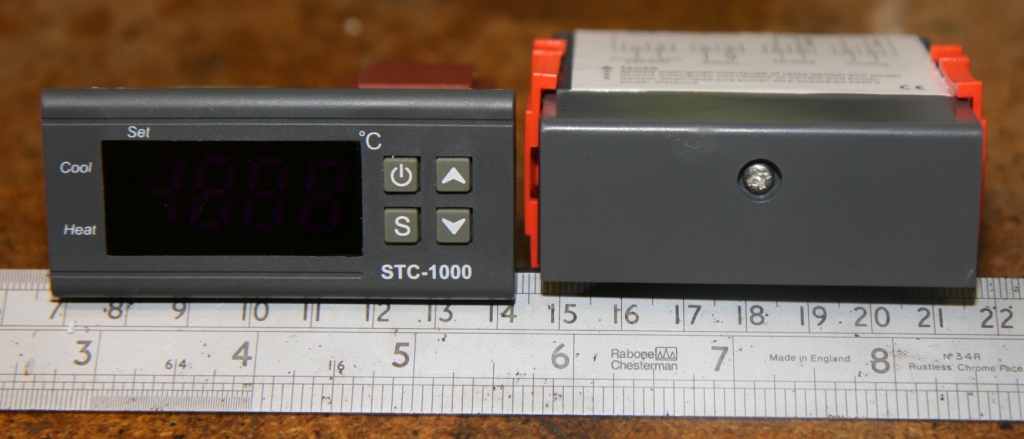
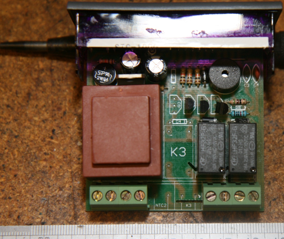
Pics attached but there is space on the board for a second sensor and a third relay. There is the crystal blocking the Pic data but what I can see is:

G80F910D
N8S7L
1407-T

There is no Design Id on the main board
The display board is:

PCB-0018 (Top left) and WK-02-K on top rhs

Hey ho!

IMG_0407.JPG


IMG_0398.JPG


IMG_0400.JPG


IMG_0402.JPG


IMG_0403.JPG
 
Wouldn't it be nice if they are planning to build a temp controller that can read 2 temps, control the fridge, and 2 heat sources. I could buy a keezer controller that could actually give me 2 separate serving temps.
 
Hi guys just got 2 STC's from China

guess what?

Yep they are a TOTALLY new design.

Pics attached but there is space on the board for a second sensor and a third relay. There is the crystal blocking the Pic data but what I can see is:

G80F910D
N8S7L
1407-T

There is no Design Id on the main board
The display board is:

PCB-0018 (Top left) and WK-02-K on top rhs

Hey ho!

G80F910 looks to be the microcontroller number, but may be a Chinese only device. Almost nothing in english in a web search.
I wonder if there are multiple factories all cranking out these things, blindly ignoring any copyrights as is typical there, and each is using their favorite controller.
 
G80F910 looks to be the microcontroller number, but may be a Chinese only device. Almost nothing in english in a web search.
I wonder if there are multiple factories all cranking out these things, blindly ignoring any copyrights as is typical there, and each is using their favorite controller.

Yes, having dipped my toe into the waters of Chinese electronics manufacturing to secure a source for the correct version of these things, I can tell you that this is exactly what's happening. They all claim to be "the factory" and will tell you that everyone else is copying them! They also typically manufacture several other versions of STC-like controllers for other purposes, which is probably the reason for the extra sensor space, etc on the board. I doubt there are any plans for them to produce a dual-sensor fridge controller as they are going for a very basic target customer with these, but I could be wrong.
 
Yes, having dipped my toe into the waters of Chinese electronics manufacturing to secure a source for the correct version of these things, I can tell you that this is exactly what's happening. They all claim to be "the factory" and will tell you that everyone else is copying them! They also typically manufacture several other versions of STC-like controllers for other purposes, which is probably the reason for the extra sensor space, etc on the board. I doubt there are any plans for them to produce a dual-sensor fridge controller as they are going for a very basic target customer with these, but I could be wrong.

I wonder if it would be worth it to make a replacement display board to swap out the non-compliant versions, reusing all the case parts and the relay board, if the compliant ones run out.
A quick check on pcb's is under $3 each for 500 pcs ($4 each for 200) at 1 site I've used in the past, for 4 layers with solder mask. The MCU is under $2, a few resistors are cheap, and the display could be swapped.

Maybe not worth the effort, unless the good ones come to an end. Or if the main board interface is not consistent. I'll look at my non-compliant ones and see if it's even realistic.
 
Well, that is a nice idea, but there are a few issues.
First off, desoldering the LED/MCU PCB from the main board is a pain. Secondly, there is no reason to believe the PCB interconnection follow any standard. You may well end up with a new PCB that only works with one version.
I would rather suggest a kickstarter or something, to develop and manufacture an open hardware/software thermostat platform. Keeping it simple and cheap with only the basic and most necessary hardware by default, but with GPIO to spare to be able to extend functionality. I imagine it like a sort of a mashup of an Arduino Uno and an STC.
 
Back
Top