Stc-1000 wiring

Homebrew Talk - Beer, Wine, Mead, & Cider Brewing Discussion Forum

Help Support Homebrew Talk - Beer, Wine, Mead, & Cider Brewing Discussion Forum:

This site may earn a commission from merchant affiliate links, including eBay, Amazon, and others.
Question for you guys... I have looked thru this thread and the schematics as well as the write up in the jan 2012 BYO. In the BYO write up there is a 10amp fuse. Rather than a fuse would it be possible to use a breaker? Either way, is this NEEDED?

Regardless as I don't know a ton about electrical before I close mine up and power it on I'm going to have my neighbor who is a handy man check my work against the schematic(s) to make sure it's all good!
 
[bytor2012
Make sure you purchased the correct STC-1000, marked 110VAC. If it is marked 220VAC or 12V, its not the right one.[/QUOTE]

what is the difference?? I purchased a 220v and live in aussie, can it be used at all??
 
what is the difference?? I purchased a 220v can it be used at all??
It can't be used from a 110V supply (normal household voltage in the US and Canada). You probably have 220v somewhere in your home (ovens and clothes dryers commonly use them), or you could run another, but you'd be way better off buying the correct STC-1000. Check your country though, some do use 220V mains.

Also, read up a bit on what it is you'll be doing, the difference between 110VAC, 220VAC, and 12VDC is something you should definitely know before you touch a wire of any voltage. Electricity at these levels is very dangerous, and wiring something incorrectly will lead to equipment failure at best, and death at worst.

This is a simple project, but that doesn't mean it can be done without a consideration for safety. fortunately, this stuff is easy to learn and once you know it, it will open up a whole world of DIY projects.
 
Pretty sure Australia runs 220/240V for standard wall outlets, so it should work just fine for you.
 
So, I wired up my STC -1000, plugged it in to test it and the unit worked, but the plug to run the fridge and heater didnt. I double checked the wiring with the schematics and video on Youtube...wired correctly. Any ideas? Bad STC board?
 
Have to say by observation over the last couple of years, most ST-1K issues are user induced.

Post a good picture of your wiring. Operative word: good.

Cheers!
 
I figured it out. It was the delay. What are the optimal settings for a ferm. Chamber besided the temp (F1)
 
I figured it out. It was the delay. What are the optimal settings for a ferm. Chamber besided the temp (F1)

F2 depends on where your probe placement is, and how tight you want the control to be. I have mine set to 0.4° IIRC. F3, the compressor delay, should be set to the max IMO, which is 10 min. F4 is to adjust the temperature reading if it's not calibrated correctly. From what I gather, most of them seem to be very accurate out of the box, and don't require any change to F4 unless you're extending the probe wires greatly.
 
It can't be used from a 110V supply (normal household voltage in the US and Canada). You probably have 220v somewhere in your home (ovens and clothes dryers commonly use them), or you could run another, but you'd be way better off buying the correct STC-1000. Check your country though, some do use 220V mains.

Also, read up a bit on what it is you'll be doing, the difference between 110VAC, 220VAC, and 12VDC is something you should definitely know before you touch a wire of any voltage. Electricity at these levels is very dangerous, and wiring something incorrectly will lead to equipment failure at best, and death at worst.

This is a simple project, but that doesn't mean it can be done without a consideration for safety. fortunately, this stuff is easy to learn and once you know it, it will open up a whole world of DIY projects.

thanks for your reply mate, I have wired up 2 STC1000's before but both were for cooling only and had no problem with them, but they were the 110 VAC variety. I wanted one for heating/cooling and I bought this one off EB without checking VAC. Thanks again
 
F2 depends on where your probe placement is, and how tight you want the control to be. I have mine set to 0.4° IIRC. F3, the compressor delay, should be set to the max IMO, which is 10 min. F4 is to adjust the temperature reading if it's not calibrated correctly. From what I gather, most of them seem to be very accurate out of the box, and don't require any change to F4 unless you're extending the probe wires greatly.

Thanks for the input/help.
 
Question for you guys... I have looked thru this thread and the schematics as well as the write up in the jan 2012 BYO. In the BYO write up there is a 10amp fuse. Rather than a fuse would it be possible to use a breaker? Either way, is this NEEDED?

Regardless as I don't know a ton about electrical before I close mine up and power it on I'm going to have my neighbor who is a handy man check my work against the schematic(s) to make sure it's all good!

As Larzean asked, I, too, read this entire thread and the Jan 2012 BYO article. The only place I see any mention of fuses is in the article but I did not see anything indicating why it is used. There is no mention of a fuse in this thread. What, exactly, is the purpose of the fuse? Is it needed? Will I run into issues with using a fuse if i'm using my control to power my keezer, a reptile heating pad and a fan that is always on?

I think I understand the wiring part but am looking for clarification on the why of the fuse.

Can anyone shed some light on this?

Thanks!
 
As Larzean asked, I, too, read this entire thread and the Jan 2012 BYO article. The only place I see any mention of fuses is in the article but I did not see anything indicating why it is used. There is no mention of a fuse in this thread. What, exactly, is the purpose of the fuse? Is it needed? Will I run into issues with using a fuse if i'm using my control to power my keezer, a reptile heating pad and a fan that is always on?


I think I understand the wiring part but am looking for clarification on the why of the fuse.


Can anyone shed some light on this?


Thanks!


The inline fuse is added as an extra protection for the STC unit. If there is too much current being drawn from the outlets, the inline fuse will blow, cutting power to the STC. If that fuse wasn't there, there is a potential for the temp controller to overheat and melt. I have heard the STC may have its own fuse, but hey, why not be extra careful. It's an extra dollar or two.
 
Would this temp controller work just the same? It uses Fahrenheit instead of Celsius, which is convenient


Docooler 10A 110V Digital Temperature Controller Thermocouple -58~194 Fahrenheit with Sensor http://amzn.com/B00F05UI8O
 
I was looking at this product again. It definitely says heat AND cool...


Honestly, just go with the STC-1000. It's tried and true and used by many people. Celsius shouldn't be a problem. I just made a small conversion chart that I keep right by it.
 
I was looking at this product again. It definitely says heat AND cool...

Yes, it can heat and cool, just not at the same time like a dual stage controller. A quick look at the wiring diagram should make that obvious. I have a couple of each, and they both serve their purposes, but they are different. For my keezer where I'll never need heat, the single stage units are fine. For my ferm fridge where I need both heating and cooling, I use the dual stage STC-1000.
 
Honestly, just go with the STC-1000. It's tried and true and used by many people. Celsius shouldn't be a problem. I just made a small conversion chart that I keep right by it.

+100. I use three of the STC-1000 units and really like them. The one controlling the fermenter fridge has a *C to *F cheat sheet.:D
 
Does the type of extension cord matter?


You mean the cord that you will wire the STC with? Well, you definitely want it to be grounded (three prong) and a wire that can handle sufficient wattage. I used a cord from a surge protector. That is generally a good bet.
 
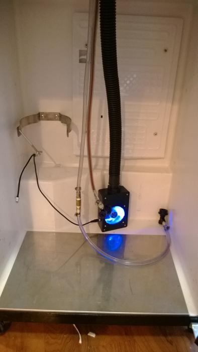
I have been lurking on the forum for a while. A friend from my brew club helped me put this together. Thanks for all of the posts.

Sent from my HTC One using Home Brew mobile app

1391430575091.jpg
 
The inline fuse is added as an extra protection for the STC unit. If there is too much current being drawn from the outlets, the inline fuse will blow, cutting power to the STC. If that fuse wasn't there, there is a potential for the temp controller to overheat and melt. I have heard the STC may have its own fuse, but hey, why not be extra careful. It's an extra dollar or two.

With regard to the fuse, I picked up a fuse holder with fuse, as described in the BYO article. However, what I'm not sure about is what kind of fuse to use. I believe the article says to use a 10A fuse. I picked up two different kinds - time delay and fast acting. Which one is more appropriate here?

Thanks for your help!!

Nice! That's exactly how I set mine up. Basically, you should be fine either way, but I would just go with a fast acting fuse.

Basically, a fast acting fuse blows immediately once current exceeds the rating. A time delay fuse will give you a little time before the fuse blows. This is normally used in an application where an appliance will use a sudden, large burst of electricity when starting up and then ramps down. That initial burst may exceed the rating and the slow blow fuse will give it a little leeway. Many fridges and freezers actually perform this way, but I don't think you will be approaching the current limits of a fuse with one.

A 10 amp fuse used in the US, will be good for an appliance up to 1200 watts. Basically, voltage x current (amps) = watts. In the US, we have 120 volt. So, 120 volts x 10 amps = 1200 watts.

I'd rather lose a fuse that costs <$1 than have my STC unit blow due to a slow blow fuse.

However, either way, you'll probably be fine. You just have to be more mindful if you are using an appliance that draws a lot of power, like a heater. A space heater may draw up to 1500 watts.
 
I figured out something weird tonight. When I aquired my freezer, it worked just fine when plugged in. But when I ram it through the controller, the plug stopped working. So I ran an extension cord over from another plug and have been running it that way all winter.

The thought occurred to my ******* that it's a GFCI plug that tripped. So I reset it and tried to plug the controller back in.

It trips every time I plug in the controller. It's not even pulling any current for the cold or hot circuit when it trips.

So I plugged it back into the extension cord and it's running fine again.

Could it just be a bad GFCI plug?
 
I figured out something weird tonight. When I aquired my freezer, it worked just fine when plugged in. But when I ram it through the controller, the plug stopped working. So I ran an extension cord over from another plug and have been running it that way all winter.

The thought occurred to my slow brain that it's a GFI plug that tripped. So I reset it and tries to plug the controller back in.

It resets but every time I plug in the controller, it trips. It's not even pulling any current for the cold or hot circuit when it trips.

So I plugged it back into the extension cord and it's running fine again.

Could it just be a bad GFI plug?

I think I may be confused as to what you are saying.

Are you saying fridge -> wall outlet works fine, but fridge -> controller -> wall outlet trips the plug? If so, does it trip when you have the controller, by itself, plugged in?

Are you 100% sure that you wired the unit correctly and properly connected the ground?
 
Really bad juju.

A properly sized GFI shouldn't trip from a fridge or freezer - and in any case, certainly not before the compressor even turns on - unless you are shipping current across the safety ground instead of neutral.

You really need to fix this. It could be something as simple as you tied a neutral wire to a ground wire, or a neutral wire got nicked and shorted to a metal chassis (that in turn is grounded via the safety ground green wire somewhere).
In any case, something is intrinsically unsafe and should be addressed pronto...

Cheers!
 
Let me give an explainer first:

My garages are detached. Garage II is the original 1938 garage. Garage I is an add on, probably in the 1980s. The wiring would have all been done when Garage I was added on. Both garages have GFCI sockets.

The ferm camber is in Garage II. Right now I have an extension cord running from Garage I into Garage II for the ferm chamber.

I was confident in my wiring. The only mistake I thought I made was not removing the bridge. I fixed that.

The controller worked fine in my kitchen when I wired it and it works fine plugged into an extension cord and run over to Garage I. When I worked on it in the kitchen it was plugged into a power strip that was not plugged into a GFCI socket.

I ran some quick tests this morning:
1) Cell phone charger does not trip Garage II. (I wanted to do a quick current check before I started unplugging and replugging things.)
2) Freezer alone does not trip Garage II.
3) Controller alone does trip Garage II.
4) Controller + 3 prong extension cord does not trip Garage I.

I did not have time this morning to unmount the controller and check it in the house again or plug it directly into Garage I.
 
Nice! That's exactly how I set mine up. Basically, you should be fine either way, but I would just go with a fast acting fuse.

Basically, a fast acting fuse blows immediately once current exceeds the rating. A time delay fuse will give you a little time before the fuse blows. This is normally used in an application where an appliance will use a sudden, large burst of electricity when starting up and then ramps down. That initial burst may exceed the rating and the slow blow fuse will give it a little leeway. Many fridges and freezers actually perform this way, but I don't think you will be approaching the current limits of a fuse with one.

A 10 amp fuse used in the US, will be good for an appliance up to 1200 watts. Basically, voltage x current (amps) = watts. In the US, we have 120 volt. So, 120 volts x 10 amps = 1200 watts.

I'd rather lose a fuse that costs <$1 than have my STC unit blow due to a slow blow fuse.

However, either way, you'll probably be fine. You just have to be more mindful if you are using an appliance that draws a lot of power, like a heater. A space heater may draw up to 1500 watts.

thanks for the advice. i'm definitely going to go the fast acting fuse route.

however, my local home depot did not have (or the worker bee i talked to could not find) a panel mount fuse holder. but they did have an inline fuse holder (link here: http://www.homedepot.com/p/Unbrande...r-12-BP-HMK-RP/203298931?N=5yc1vZbtvmZ1z10wqj) will this work just as well? i picked up some 10A fuses that i will use instead of the included 20A (or 30A) fuses that came with it.

any issues with this method? otherwise, i guess i can order a panel mount one from china (any other big box stores carry the panel mount variety?).

thanks!!!
 
Beernik, that sounds very strange. So you are saying when you plug the controller in, by itself, it trips the outlet? And then if you plug the controller into an extension cord first and that into the same outlet, it doesn't trip? If that's the case, I'm not really sure what the deal is since the extension cord essentially does just that, extends the cord. Maybe have an electrician look at it if you are really concerned, or maybe just use a different outlet if possible.

thanks for the advice. i'm definitely going to go the fast acting fuse route.

however, my local home depot did not have (or the worker bee i talked to could not find) a panel mount fuse holder. but they did have an inline fuse holder (link here: http://www.homedepot.com/p/Unbrande...r-12-BP-HMK-RP/203298931?N=5yc1vZbtvmZ1z10wqj) will this work just as well? i picked up some 10A fuses that i will use instead of the included 20A (or 30A) fuses that came with it.

any issues with this method? otherwise, i guess i can order a panel mount one from china (any other big box stores carry the panel mount variety?).

thanks!!!

You'll be fine with that method. I used pretty much the same inline fuse holder. If the fuse holder is rated up to 20 or 30A, you can still use a lower amperage fuse in it (like a 10 amp). That's what I would do.

Just make sure you wire the inline fuse holder in the correct location. The way I wired mine was:

hot wire from the power cord -> input of inline fuse holder w/wire nut -> output of fuse holder w/ wire nut with three individual hot wires to the STC power input, the heat input, and the cooling input.
 
Thehopbandit,

It's plugged into an extension cord into a different outlet.

I haven't tried into the extension cord into the same outlet. Getting the extension cord into the rafters of the two garages was a PITA. I'm not taking it down until I know I don't need it anymore. I can check with a different extension cord tonight.
 
If it helps, here is a picture. Garage II is behind the turkey fryer. Garage I is to the right. My neighbor's garage is to the left. On the inside, Garage II looks just like the neighbor's garage with another garage added on.

The reason I call it Garage II is because it was built to fit a Model T. So not much bigger than a compact fits in it. And even then, you have to shimmy in and out of the car. (A Model T is shorter than a Ford Fiesta).

Garage I will fit a full sized truck.

Also, if it helps, I have little confidence in the workmanship of the guy who did the garage addition. I had to re-shingle the roof in 2010. The garage is about 2 feet out of square in its depth. No joke. It picked up over a tab and a half going across it.

image.jpg
 
Between valentines, picking up a bed from my brother, attending a funeral, and prepping a room for painting, I managed to try plugging the controller into an extension cord and into Garage II. It still trips the GFCI.

So here's what I know:
1. The only thing that trips the GFCI in Garage II is the controller.
2. The only place the controller trips a GFCI is in Garage II.

There must be something faulty with one of them. I'll check the controller first because it's free. But it may not be until Monday.
Since the controller is hand wired, I suspect you have something miss-wired. Don't know why it would only trip certain GFCIs.

How many other GFCIs did you test it with? It's a long shot, but maybe the controller has a fault AND the non-Garage II GFCI(s) is(are) bad.
 
It trips two GFCIs, it does not trip one

Finally had time to get to this and I'm no longer worried about my garage freezing at night.

I've double checked my wiring.

Originally, it was wired like this
Now it is wired like this

So it wired:
Hot block goes to: main plug, 1, 5, 7
Neutral block goes to: 2, cold2, hot2
Earth block goes to: main plug, cold2, hot2
6 goes to: hot1
8 goes to: cold1

cold1 and cold2 are opposite sides of the cold plug
hot1 and hot2 are opposite sides of the hot plug

Both ways trip the GFCI. It trips immediately upon plugging in. It works fine when plugged into a non-GFCI.

I can't see where any wires are bare or touching.

I'm not sure what to do other than rewire it all from scratch.
 
Back
Top