• Please visit and share your knowledge at our sister communities:
  • If you have not, please join our official Homebrewing Facebook Group!

    Homebrewing Facebook Group

Stc-1000 wiring

Homebrew Talk

Help Support Homebrew Talk:

This site may earn a commission from merchant affiliate links, including eBay, Amazon, and others.
Neutral block

image.jpg
 
Well day_trippr, dolomieu, and raouliii, thank you for your help tonight. It is working and not tripping the GFCI in the bathroom.

I have a little cleanup work and I'll be mounting it back on the freezer tomorrow.

EDIT: I have the jumper removed.
 
I'm not gonna bother to go back, but I'm pretty sure the "don't tie ground to neutral" thing was mentioned a long time ago.

Glad you got it working finally. There's not much point in having GFI protected circuits if you can't plug something into 'em ;)

Cheers!
 
Howdy all - using this thread we tried to wire up a couple of these devices (I bought two figuring to have a backup or use two different devices for fermentation chambers, we just built one that can hold a few ale pails and car boys bugt if I need to do something seperate, orif this one crapped out I am covered.).
I liked the idea of dedicated "always on, heat and cool" seperately. As far as I can tell we did everything correctly but it doesn't supply power to the heat and cool outlets. The thermostat portion definitely works - I can put probe in ice water or hold it in my hand and it changes rapidly. I can hear the "click" when it gets past the set point that indicates it is supposed to be kicking on the heat or cool (and the light indicates heat or cool on the stc1000). The problem is that neither the heat or cool duplexes get any power. We used an ohm or volt meter (obciously I am not experienced with things electrical but he is a handyman and he thought it was simple and straight forward). We see the results of the temp changes on the unit, we hear the click that says " going to cooling or heating now" but after that - nothing happens.I even put the cycle on one minute in case we weren t waiting long enough to measure but nothing. The always on duplex works fine so I just have to check the temp and then manually plug in the mini fridge or the heat lamp into the always on plugs but that kind of defeats the purpose.

Hopefully someone out there knows the cause. The units seem to work. The wiring in first one (where all portions were wired, therefore I should be able to plug the fridge into cool, lamp into heat) SEEMS to be correct. The second unit we just did the main power and temp probe and then measured the other outputs after they clicked on - but got 000s all the way thru.

Any ideas? Thanks for any help from the experts, my beer and my friends will appreciate these things working the way they are supposed to, and I will be eternally grateful.
Cheers
jeff
 
manowarfan1,

Can you provide a diagram of how you wired it up? I can use that to offer some possible suggestions.
 
As far as I can tell we did everything correctly but it doesn't supply power to the heat and cool outlets.

The second unit we just did the main power and temp probe and then measured the other outputs after they clicked on - but got 000s all the way thru.

These two sentences strongly suggest that you didn't wire it correctly. The unit doesn't supply power to the outlets, it's simply a switch, so of course the terminals are going to read zeros without anything connected to them. The terminals aren't "outputs", they're two sides of a switch. You need to provide power to one side, and run the other side to the your heater or fridge outlet. As mentioned, if you can post a wiring diagram we can likely get it sorted out for you.
 
We were going by the diamgram with the 3 outlets, but after I get home from work I will try to take a picture of how it came out, I think i can get everything out of the box without unwiring anything.
Thanks for any assistance.
Jeff
 
We were going by the diamgram with the 3 outlets, but after I get home from work I will try to take a picture of how it came out, I think i can get everything out of the box without unwiring anything.

Thanks for any assistance.

Jeff


You need to ensure that you have a hot wire going to the unit input, the hot input, and the cold input. This is usually accomplished by using a wire nut to bind an incoming hot line with three wires for each of the unit inputs. The outputs from the unit would then go to the outlet screws.

Also make sure your neutral and ground wires are correctly wired.

This image illustrates what I am talking about:
https://cdn.homebrewtalk.com/gallery/data/500/medium/STC-1000_outlet_wiring.jpg
 
A lot of us just use a "replacement power tool cord" or even cut apart an extension cord. I usually buy larger that I need, so I can cut a few feet off to use to actually wire it.

PartsIsParts.JPG


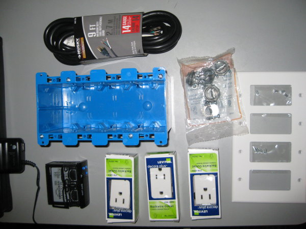
Here's a basic parts list....

R62-16252-0WS Leviton 15-Amp White Decora Plus Duplex Outlet (as many as needed)
R52-PJ264-00W Leviton White Midway Nylon Wallplate (As many "gangs" (Slots as needed)
AW62632 Husky 9 Ft. 14-3 Power Tool Replacement Cord
B468R CARLON Electrical Wall Box (As many "gangs" as needed)
20511 Halex No. 20511, 3/8 In. Pack of 5 Twin Screw Clamp Connector
STC 1000 Dual stage temperature Controller w/probe

I based mine on Tom's design...His thread is good, I have only the slightest knowledge of doing this stuff. I can switch out a bad wall socket but that's about it. And I really didn't have trouble doing this.

In fact I just wired one up with only 3 gangs (Not an always on) and did it without a diagram.

I just purchased mine and am awaiting its arrival to get it up and running...can't wait....good info on this thread so thank you. Question about that extra Husky brand electrical cord. Are you essentially slicing a cut portion of that open and using the green, black and white wires in that to hook everything up?
 
Question about that extra Husky brand electrical cord. Are you essentially slicing a cut portion of that open and using the green, black and white wires in that to hook everything up?

That's it. Cut off the end (the female plug) then strip down the black insulation to expose the three inner wires to an appropriate length. The black insulation is probably molded to the wires, so I find careful use of a utility knife works better than any sort of stripping device.
 
Back
Top