• Please visit and share your knowledge at our sister communities:
  • If you have not, please join our official Homebrewing Facebook Group!

    Homebrewing Facebook Group

Stc-1000 wiring

Homebrew Talk

Help Support Homebrew Talk:

This site may earn a commission from merchant affiliate links, including eBay, Amazon, and others.
Sir Humpsalot said:
Sorry for the threadjack.... I was about to pull the trigger on one of these, and then I got to thinking...

$25 STC1000
$7 Extension cord
$10 project box
A pair of $10 GFCI sockets

And I'm within ten or fifteen bucks of the price of a Johnson controller....

Not to dismiss what you all have done. I think it's great, and it looks cool as heck, and I'm a big fan of DIY... I saved some coin by making my stirplate and really enjoy little electrical projects... But I'm thinking that the savings over the Johnson controller isn't all that great when you add it all up. I'm not looking for an argument here, it's just an honest question.

Anybody care to agree or disagree?

The johnson is only single stage, the STC-1000 is dual stage. The johnson is also analog with no compressor delay and no way to change/adjust the temp differential. The cost is similar, but the STC-1000 has a lot more features and functionality. Nothing wrong with the johnson controller, especially for a keezer or other applications that only require single stage control, but it's not really a comparable product. A better comparison would be a ranco dual stage controller, which runs ~$120 IIRC

And FWIW it can be put together significantly cheaper than the price list you have there.

All of this^

Plus you can mount the stc-1000 in your collar and it looks cool!
 
So I have been reading these wiring threads for a bit and I am a little confused. I am only going to be using the STC-1000 for cooling. Basicly the controller just applies or removed power from the socket you will have you freezer plugged into right? If so would this simple diagram work?

I havent looked at the STC for a bit but I assume hot and neutral go to it on pins 1 and 2.... or is 2 a ground
 
Nevermind. I think I went full retard for a second. Pins 7 and 8 are hot in and hot out respectivly. So the neutral would come right off the plug right? Like this

232323232%7Ffp635%3A5%3Enu%3D5664%3E252%3E25%3A%3EWSNRCG%3D3574%3A6358534%3Bnu0mrj
 
Nevermind. I think I went full retard for a second. Pins 7 and 8 are hot in and hot out respectivly. So the neutral would come right off the plug right? Like this

232323232%7Ffp635%3A5%3Enu%3D5664%3E252%3E25%3A%3EWSNRCG%3D3574%3A6358534%3Bnu0mrj

This one is correct, except the hot and neutral connections to the receptacle should be reversed with it facing as shown. When looking at the front of the receptacle the neutral is on the left and the hot is on the right.
 
Sir Humpsalot said:
$25 STC1000
$7 Extension cord
$10 project box
A pair of $10 GFCI sockets

Anybody care to agree or disagree?

You can get the STC-1000 for $23

I use the 16/3 cord so I have a ground there $10

Romex boxes are cheaper, but the box I use is nearly $9 with the fancy cover plate.

Why do you need a pair of GFCIs? I use one standard outlet at $3

I'm at $45 vs your $62 and it can be done a few bucks cheaper with less pretty parts.
 
I have both a Johnson and the STC-1000 now. I like the STC-1000 better. My biggest beef with the Johnson controller is that to change the temperature setpoint, you have to press the up or down button once for each degree. You can't just hold the button down and let it scroll to the setting you want. So that is a real pain when wanting to change between say 75F or keeping something warm to 195F for broth making and then back again, pressing that @&$!@ button 120 times each way is reallllllyyy irritating.

I used a Yellow Jacket 14/3 extension cord I got for $14 from Lowes, a 3 gang box, and bought a 10 pack of decora outlets since I'm going to make two of these beauties. I debated on the GFCI and went without it, I just don't like them in refrigeration applications. They're not supposed to trip falsely but there many people seem to have trouble with nuisance tripping when used with refrigerators and freezers.

The Johnson does have a temperature differential, at least mine does, in the settings. But right, it's just a single relay contact. You could wire up heat of the NC contact and cool off the NO contact but it would be always running heat or cold then, no condition where it's neither heating nor cooling.
 
This may have been discussed?? I just received my STC-1000 yesterday. Nice looking unit.

Question is: How much of a load can this handle on 110vac? The instructions say it's 10A @ 250vac for both heating and cooling. What does that translate to @ 110/120vac?

Thanks, Bill
 
I noticed you subscribed to two threads I posted my diagram in. Do you have any specific questions.

Yep, now I do.. I like the schematics both you and JuanM posted. I'd really like to combine the two. IOW, Have the controller fed from a non-controlled duplex like you/Revvy has.. so the duplex is not tied up.. then only have one duplex on the output side like JM's but have half of the controlled duplex for heating and the other half for cooling.

I think I understand how to do it.. but, great graphics are a real aid to a retard like me.
 
This may have been discussed?? I just received my STC-1000 yesterday. Nice looking unit.

Question is: How much of a load can this handle on 110vac? The instructions say it's 10A @ 250vac for both heating and cooling. What does that translate to @ 110/120vac?

Thanks, Bill

It sounds like they might have accidentally sent you a 220V unit instead of a 110V unit like they did to me.... I had to contact the shipper and get them to send me the 110V.
 
Question is: How much of a load can this handle on 110vac? The instructions say it's 10A @ 250vac for both heating and cooling. What does that translate to @ 110/120vac?

Thanks, Bill
If it is rated for 10A @ 250VAC, it will handle at least 10A at 110VAC. If you take off the controller housing, you can look at the relays themselves to see what they are rated for. (Although, I have seen some funky numbers on Chinese parts.) Either way, 10A is more than enough for any compressor or heat source for fermenting/serving. Any other application, like an E-brewing vessel, should use an SSR controlled by the relay in the STC-1000. However, for E-brewing, a better choice is a cheap PID with built in SSR output.
 
This may have been discussed?? I just received my STC-1000 yesterday. Nice looking unit.

Question is: How much of a load can this handle on 110vac? The instructions say it's 10A @ 250vac for both heating and cooling. What does that translate to @ 110/120vac?

Thanks, Bill

Being the inquisitive sort, I opened up an STC-1000 110v unit. The relays inside are marked 12vdc-1hs for the coil and 10A 277VAC, 15A 125VAC for the contacts. Leads me to a couple of conclusions.

1) at 120V a 15A load is acceptable
2) the relays may be removed and the coil signal output to an SSR for higher loads.

I'll test #2 shortly, as I want to switch a larger load on a non-brewery application.
 
Don't know how to tell.. the outside of the box says 110v

My box also said 110v. As helibrewer mentioned, the schematic sticker on the unit will show either 110v or 220v at the AC connection point. Or you can go the route of opening it and looking at the transformer or relays as mentioned above. I believe both are rated at 10A. I still have the 220v unit that they sent. They said I could keep it if I paid five additional dollars to ship the 110v. So I ended up getting both units for $28. I found a thread on this forum that expalins how to convert the 220v over to 110v. I'll link it if you need it...
 
Thanks guys, my controller says 110v.. but the instructions are what have the 10A@250vac. My understanding was that the amperage is what drives things. For instance.. in cars of yesteryear, we had 6vdc systems. The wires were "huge" compared to the 12vdc systems in cars of the same vintage. Everything about a 6v system was beefier. I would think, intuitively, that the ratings for a 10A@250vac would be about 1/2 the rating.. but, I'm not an E engineer.
 
Being the inquisitive sort, I opened up an STC-1000 110v unit. The relays inside are marked 12vdc-1hs for the coil and 10A 277VAC, 15A 125VAC for the contacts. Leads me to a couple of conclusions.

1) at 120V a 15A load is acceptable
I would consider a 15A load pushing it. Staying within ~80% seems more prudent.

2) the relays may be removed and the coil signal output to an SSR for higher loads.
There is no need to remove the relays to use an SSR, just use the relay to switch a 12V wall wart. For a permanent SSR solution, a cheap (~$35) PID controller with PID, on/off, and manual control (% On) make more sense, unless you already have an extra STC-1000 you will never use for anything else.
 
I would think, intuitively, that the ratings for a 10A@250vac would be about 1/2 the rating.. but, I'm not an E engineer.
The ratings on the relays themselves are a bit dubious. Generally, relays are limited, separately, by a voltage and a current. The relays in these units have different current rating for 220VAC and 110VAC. Those ratings seem to be related more closely to typical max household circuit breaker size in the US and EU, than any engineering analysis of the relays.
 
How long do you expect the compressor to go on for??? Cooling to 60F in most climates, I would think several minutes at a time. I think there is usually a big surge at start-up of the compressor, then when it's running it's only pulling a few hundred watts for your modern freezer.
 
How about the ones that look *exactly* like the ones that came with it, and are sometimes even sold by the same seller? I have seen both the rubberized and stainless ones sold separately.

Additionally, these controllers are knockoffs, and the sensors they use are certainly the most commonly used NTC thermistor spec. The threaded sensors that Emjay linked have been used successfully by more than a few people. Whether it was dumb luck, or, more likely, a result of most manufacturers of -50C to 200C controllers using the exact same spec for thermistors- the *impossible* work, as you characterize it, has been done, and links provided.

I also highly doubt these controllers are 'batch programmed' to particular runs of sensors, and even less likely that the controller itself is tuned for the batches of all of its internal components. The actual tolerances of discrete parts are much closer than spec sheets portray, especially for a part operating within a very small region of the part's range, like the sensor we are dealing with here.

There is no need to make everything seem so difficult.

Hi

Oddly enough, I've actually been in the sort of places that "knock off" this sort of stuff. The way they do it is pretty simple. They all get a specific batch of parts from a single source. Each of them build up the parts and sell them. That way they don't have to worry about complicated things like getting the right this or that. It also lets them buy thermistors in large enough batches to get them made right.

Bob
 
Anyone know if the STC-1000 will push enough amps to start up a Holiday 7cu chest freezer set up in my garage?

Here are some specs from the back of the freezer:
Voltage: 115v~60Hz
Amps:1.70A
Startup Amps: 12A
 
It should have no issues with that load. The running load is minimal and even the starting load is below the relay rating. I'm using it on a GE 7 cu ft chest freezer I am guessing has similar specs and it is working fine.
 
FWIW, here's a pdf datasheet for the relay.

About what I figured. The relay spec looks like it is 277VAC and 15A. The different ratings printed on the relay itself are just test certifications for common load limits for US and EU certs. The max power rating seems like it is just the max power for its 277VAC test cert. From what I remember, V is mostly limited by contact arcing issues, and A is mostly limited by contact fusing issues.

Looking at the cycles/ops data shows the effects of working at the upper current limit. It decreases the life by 1/2 going from 7 to 10A (100k vs 50k). Going to 15A would be much less life, since the cycles vs. amps plot isn't likely to be a straight line. Depending on your usage, a 15A load may or may not be an issue. A guess for the typical ops for a keezer is ~10k/yr, but they are only ~5A.
 
Hi

Oddly enough, I've actually been in the sort of places that "knock off" this sort of stuff. The way they do it is pretty simple. They all get a specific batch of parts from a single source. Each of them build up the parts and sell them. That way they don't have to worry about complicated things like getting the right this or that. It also lets them buy thermistors in large enough batches to get them made right.

Bob
I think you are giving them too much credit, and complicating things again. I doubt anyone goes to the trouble of verifying the (out of) tolerance for each batch of discrete components, and then adjusts things to create a matched component set. I think a more plausible scenario is they build up the controller from whatever batches of parts they have; calibrate the meter to a known resistance; then toss in one of sensors from whatever batch.

Thermistors of all specs are commonly available enough that they don't need to 'get them made right', they just need to decide how much accuracy they want to pay for. The price difference can't be much either, since even stateside high quality ones can be had for $0.10 in bulk.

These controllers are not lab test gear that have to read a host of sensors and a wide range of temps. They can be optimized to be forgiving for the limited usage range. As Emjay's results show, any replacement sensor of the same spec will work for the range of temps of the controller. He didn't even need to use the calibration setting, but it is there if needed. Probably a case of "that may work in real life, but it will never work in theory".

I think a big reason they chose thermistors is because of the relatively flat response curve that can be created for the typical temp range. That, and cost. Thermistors are arguably the best sensor choice for this range of temps- less calibration, less required meter sensitivity, easy to linearize, ease of manufacture, ... the list goes on.
 
Anyone know if the STC-1000 will push enough amps to start up a Holiday 7cu chest freezer set up in my garage?

Here are some specs from the back of the freezer:
Voltage: 115v~60Hz
Amps:1.70A
Startup Amps: 12A

It should have no issues with that load. The running load is minimal and even the starting load is below the relay rating. I'm using it on a GE 7 cu ft chest freezer I am guessing has similar specs and it is working fine.
Additionally, the peak in-rush/startup current probably occurs for a short enough time, long enough after the relay closes, and isn't a factor for relay opening, so that it isn't even relevant to the relay function or life expectancy. The startup current is more for circuit breaker limits.
 
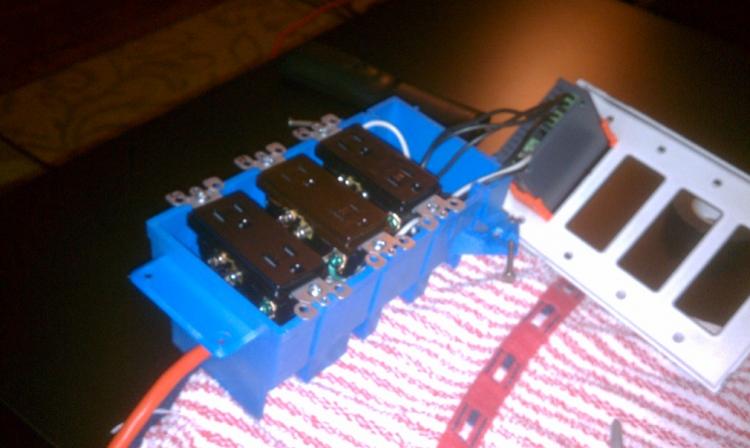
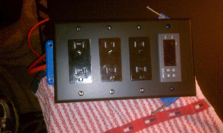
I put together and tested my temp controller tonight, using Revvy's diagram from the first page of this thread. Thanks Revvy! It works wonderfully.

Funny story, I used Home Depot's in-store pickup on their web site to try and save some time. It took 20 minutes for the 3 employees to figure out how to ring out my order. Also, the extension cord they picked was not the one I had ordered. Easy enough, I just swapped it for the right one in store. Tonight, after I wired everything up, I realize one of my outlets is BROWN, not BLACK. Ugh! I don't feel like tearing this thing apart, so it's going to stay as my reminder never to use Home Depot in-store pickup again!

IMAG0757_resize.jpg


IMAG0759_resize.jpg


IMAG0760_resize.jpg
 
I put together and tested my temp controller tonight, using Revvy's diagram from the first page of this thread. Thanks Revvy! It works wonderfully.....
I'll offer up a comment on your build. The wide slot of the receptacles is defined by code as neutral. Correct me if wrong, but it appears you have hot connected to that side of your receptacles. Any single pole switches internal to appliances connected to the receptacles will be switching neutral instead of hot. While this configuration will work, it is not the best situation and can be unsafe depending on the design of the appliances.
 
Back
Top