• Please visit and share your knowledge at our sister communities:
  • If you have not, please join our official Homebrewing Facebook Group!

    Homebrewing Facebook Group

starting on a new controller

Homebrew Talk

Help Support Homebrew Talk:

This site may earn a commission from merchant affiliate links, including eBay, Amazon, and others.

inda_bebe

Well-Known Member
Joined
Jan 13, 2012
Messages
216
Reaction score
6
Location
orange
Ive started buying the basic parts for my electric controller.
-auber 2325
-rtd temp probe
-2 40a SSR
-2 120v contacter?

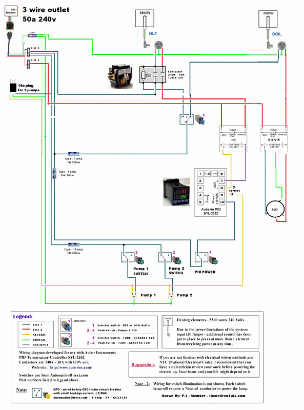
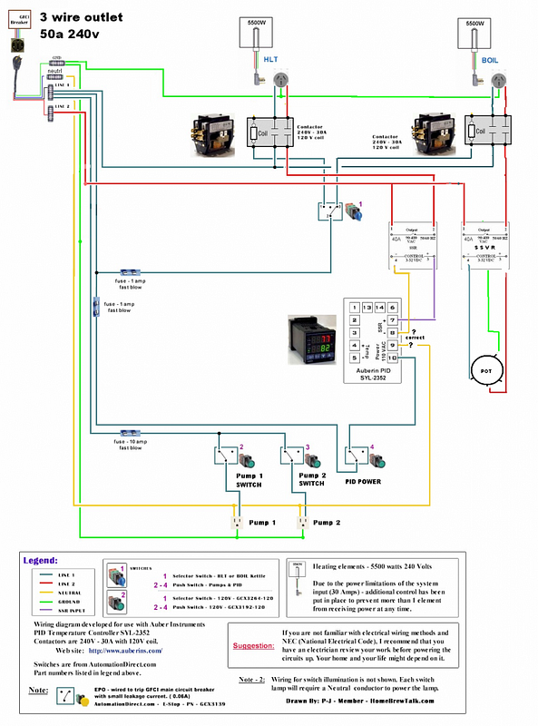
I plan to use 2 5500w elements in each HLT and BK.
HLT controlled by PID
BK controlled by PWM
2 pump outlets
3 way selector switch so that only one vessel can be controlled at a time.

I'm having a hard time finding a selector switch rated for 50a. Also, I have a 3 wire 50a 240v outlet.

I'm still searching for plans so any diagrams and links will be helpful
 
Check out the electric brewery if you havent already. He uses a 120 volt selector switch to control solenoids which provide the high voltage. I would recommend though to use double pull double throw solenoids so that you can cut off all power to the elements when not in use rather than just one leg. Does your outlet have two hots and a ground? If so, you will need to provide a neutral for your 120 volt power. Someone else might have a better understanding but I would think that your best bet would be to pull from another wall outlet for 120 and use the 240 volt outlet exclusively for powering the heaters.
 
will this potentometer work for the boil kettle?

$(KGrHqVHJBkFJSENjRWuBSW-vVYlgw~~60_3.JPG


$(KGrHqQOKpkFGculBbsEBSW-vr!I2w~~60_3.JPG


http://www.ebay.com/itm/US-NEW-WTH1...266?pt=LH_DefaultDomain_0&hash=item51ba7c0672
 
do you stick your tongue in a light socket to see if it's live?
You have a lot of reading to do my friend
 
Sure it will work if you add an SSVR .
I will post a schematic diagram soon.

Thanks for the positive reply. Ive built a rims tube controller that worked well but it used 120v. I just started using 240v and my brewday is a lot quicker
 
This diagram is for Mypin TA4 but any other PID with SSR output can be used.

Sorry, diagram is not fancy.

You don't need a low voltage power source across the pot for the SSR?

I didn't know they had their own power, or does it have the ability to change based on the resistive input.

I am planning to build something similar for my brew partner.

***EDIT***: I see that it is a SSVR, must be the difference. So if you have a SSR I am guessing you would need to add a low V power source.
 
SSR connected to a PID is controlled by voltage and it can be either On or Off. Doesn't matter what voltage your are applying (in 3-32Volt range).
This is an example of such SSR - http://www.ebay.com/itm/New-Solid-S...80V-40A-3-32VDC-D4840-NEW-DC-AC-/331084563189

To make a variable power control with that SSR you need a PWM module with 1-2 sec period and an additional power suplay.

But there is a simpler way - use a SSVR. SSVR controlled by pot and doesn't requires additional power supply.

For example -
http://www.ebay.com/itm/Single-Phas...tance-Regulator-40A-AC-25-380V-/230913398845?
or
http://www.ebay.com/itm/1pc-KYOTTO-AC-Solid-State-Relay-SSR-KR2040AX-280VAC-40A-/140553987088
 
i ordered the DIY kit from stilldragon, and ill use the parts from that to blend with my pid.
 
how would you go about modifying this plan to add the pwm and ssvr on the BK side? i dont have the 4 wire installed, only 3. what should i do w/ the neutral? im gonna go with single elements each for now, since im only doing 10 gal. but making room in the box to add when needed.
Auberin-wiring1-a4-5500w-30a-e-stop.jpg
 
Check out the electric brewery if you havent already. He uses a 120 volt selector switch to control solenoids which provide the high voltage. I would recommend though to use double pull double throw solenoids so that you can cut off all power to the elements when not in use rather than just one leg.
Replace the word "solenoid" with "relay" or "contactor" and you've got it right... ;)

(A solenoid is something different)

Kal
 
i modified the plan i copied from above. Hoping this is correct

1- Is a Contactor needed for the SSVR?

2- Is the PID Power and SSR hooked up correctly?

3- I will be running a seperate line for the pumps since its only a 3 wire 240 v. can i share 1 hot and ground and run a seperate neutral? or should all 3 be seperate?

4- or does NO. 9 on the PID go to Neutral on the 120v side?

5- Is everything correct? can i start building this thing already?

plan3_zpsabb77136.png
[/URL][/IMG]

plan4_zpse1fe4f40.png
 
i modified the plan i copied from above. Hoping this is correct

1- Is a Contactor needed for the SSVR?

2- Is the PID Power and SSR hooked up correctly?

3- I will be running a seperate line for the pumps since its only a 3 wire 240 v. can i share 1 hot and ground and run a seperate neutral? or should all 3 be seperate?

4- or does NO. 9 on the PID go to Neutral on the 120v side?

5- Is everything correct? can i start building this thing already?

1. If your are going to use a contactor for HLT and a low amp switch you will need a second contactor for BK,

2- PID and SSR hooked up correctly.

3- 3 prong outlet provides 2 hots and a neutral. So technically you need a separate grounding only.

4- This PID has universal power supply and can work either on 120V or 240 Volt. So you can connect two hots to it or one hot and one neutral.

5- Fix the issue with SSVR contactor by adding one more contactor or use only one contactor as main switch and select between HLT and BK by switching control circuits of SSR/SSVR as depicted on my diagram above.

plan1_zpsa4f4a6bc.png


1- is NO. 9 & 10 on the PID correct or is it backwards?
2- then i dont need a seperate 120v line for the pumps, correct? i can just tap into the main 240v?
3- where should i ground it to if i only have a 3 wire outlet?


*This is the original version of a plan i modified:
plan5_zps5d9695f2.png

Then P-J corrected it to my needs. Thanks
 
- The left switch controlling contactors is redundant . You can remove it at all.
- Instead of two 30A contactors for HLT you can use one with 50A or 60A rtaing
- To control both HLT elements you need 50A or better 60A (or even 80A) rated SSR.
- 9 and 10 pins on SSR are interchangeable so it doesn't matter how to wire them.
- You can use neutral instead of ground. But it's better to get real ground somewhere. Check your 50A outlet's box. It's likely to have a ground wire inside. So you can just replace 3 prong outlet to 4 prong.
 
Oh well - There WAS a diagram posted by inda_bebe that I spent a few hours messing with and modifying. It's not appearing in this thread anymore... It's a shame - but - I'll post the result of my effort anyway. By the way it is a full scale image -but- as an attachment the system resizes it. It you want it full scale - let me know.

plan5_zps5d9695f2.jpg
 
Oh well - There WAS a diagram posted by inda_bebe that I spent a few hours messing with and modifying. It's not appearing in this thread anymore... It's a shame - but - I'll post the result of my effort anyway. By the way it is a full scale image -but- as an attachment the system resizes it. It you want it full scale - let me know.

Perfect. Getting parts tomorrow. Sucks cause have 2 120v contractors.

Why do i see some builds use 120v contactors but this one uses 240v? just trying to understand it better.

Saw it from another build and thought that was needed. Thanks for the revised diagram. Visual helped and was easier for me to understand. can i get a full scale copy please? its pretty hard the read all the part numbers and specs.

The 240V contactors are there because the power source for them is derived from your 240V power source. The 240V source in independent from the 120V source.

The full scale diagram can be saved to your computer and is here:

plan5_zps5d9695f2.jpg


Hope this helps you.
 
After looking very closely at the contactor images, it appears that the contactor only opens one of the 240V connections. I'd not recommend it for a 240V E-Brew setup.

Sorry about that.
So is auberins the place to source it from? Any place cheaper? And it has to be 2 pole, correct?

How's this one
http://www.ebay.com/itm/NEW-FREE-SH...814?pt=LH_DefaultDomain_0&hash=item27d431992e
$(KGrHqJHJDgFG8yjfvygBR0tyDWHrg~~60_12.JPG

http://www.ebay.com/itm/NEW-FREE-SHIPPING-Contactor-30A-2-Poles-240V-/171063744814?pt=LH_DefaultDomain_0&hash=item27d431992e
 

Latest posts

Back
Top