Ive started buying the basic parts for my electric controller.
-auber 2325
-rtd temp probe
-2 40a SSR
-2 120v contacter?
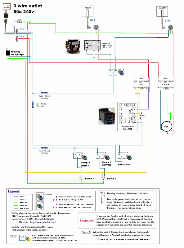
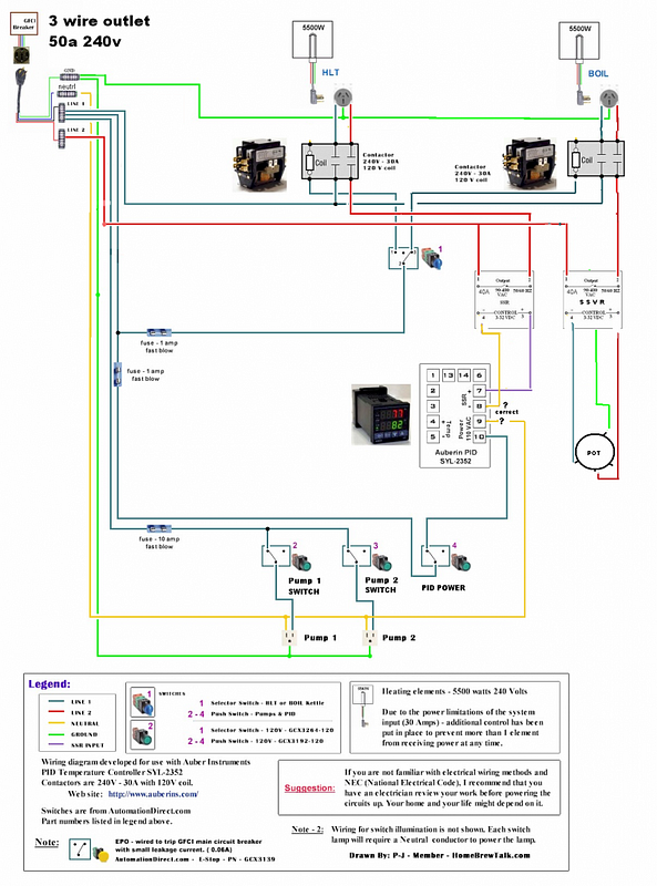
I plan to use 2 5500w elements in each HLT and BK.
HLT controlled by PID
BK controlled by PWM
2 pump outlets
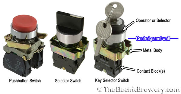
3 way selector switch so that only one vessel can be controlled at a time.
I'm having a hard time finding a selector switch rated for 50a. Also, I have a 3 wire 50a 240v outlet.
I'm still searching for plans so any diagrams and links will be helpful
-auber 2325
-rtd temp probe
-2 40a SSR
-2 120v contacter?
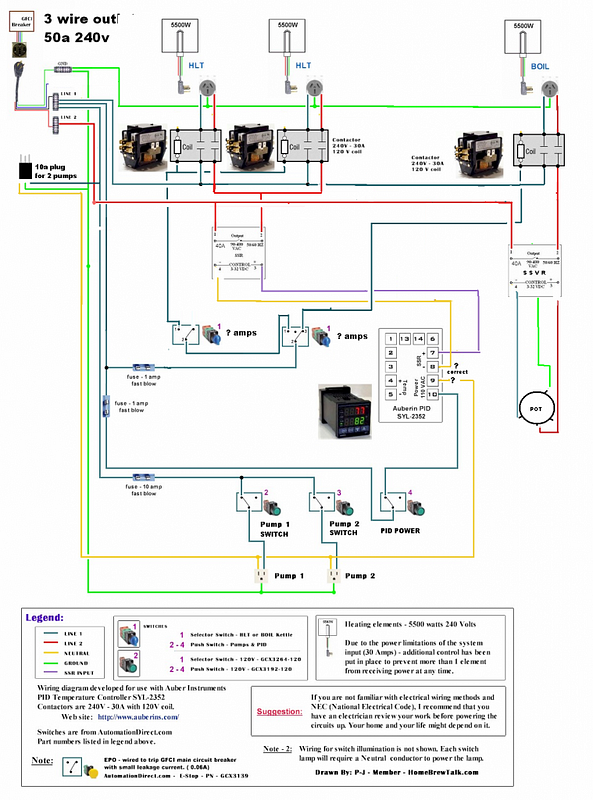
I plan to use 2 5500w elements in each HLT and BK.
HLT controlled by PID
BK controlled by PWM
2 pump outlets
3 way selector switch so that only one vessel can be controlled at a time.
I'm having a hard time finding a selector switch rated for 50a. Also, I have a 3 wire 50a 240v outlet.
I'm still searching for plans so any diagrams and links will be helpful


")