Side-by-side converted to single chamber fermenter

Homebrew Talk - Beer, Wine, Mead, & Cider Brewing Discussion Forum

Help Support Homebrew Talk - Beer, Wine, Mead, & Cider Brewing Discussion Forum:

This site may earn a commission from merchant affiliate links, including eBay, Amazon, and others.

YeastFeast

Supporting Member
HBT Supporter
Joined
Nov 9, 2013
Messages
387
Reaction score
234
Location
Bratwurst City, WI
I was previously using a wine fridge which I converted to a fermentation chamber for my brew bucket (controlled by a BrewPi). Worked great until I added a Spike CF5 conical which needed a bigger fermenting space.

My main inspiration came from Boerderij_Kabouter and this build: Side-by-Side to Fermentation Chamber Build

I decided I didn't need extra freezer space and I also already have a keezer so having one big chamber made the most sense to me.

Purchased this one for $100 from a friend who also delivered it.
tempImagerQpeCD.jpg

tempImageITHzHC.jpg


After a major cleaning and gutting of almost everything inside, I cut out the ice/water dispenser. It was dirty and crusty and no need for it.

tempImage9r48fQ.jpg


Sealed up the front with a piece of sheet metal, shot a can of spray seal in the hole and covered the inside with a floor board I had laying around.
tempImageBnTiqm.jpg

tempImagerKew73.jpg

tempImageuk58fl.jpg


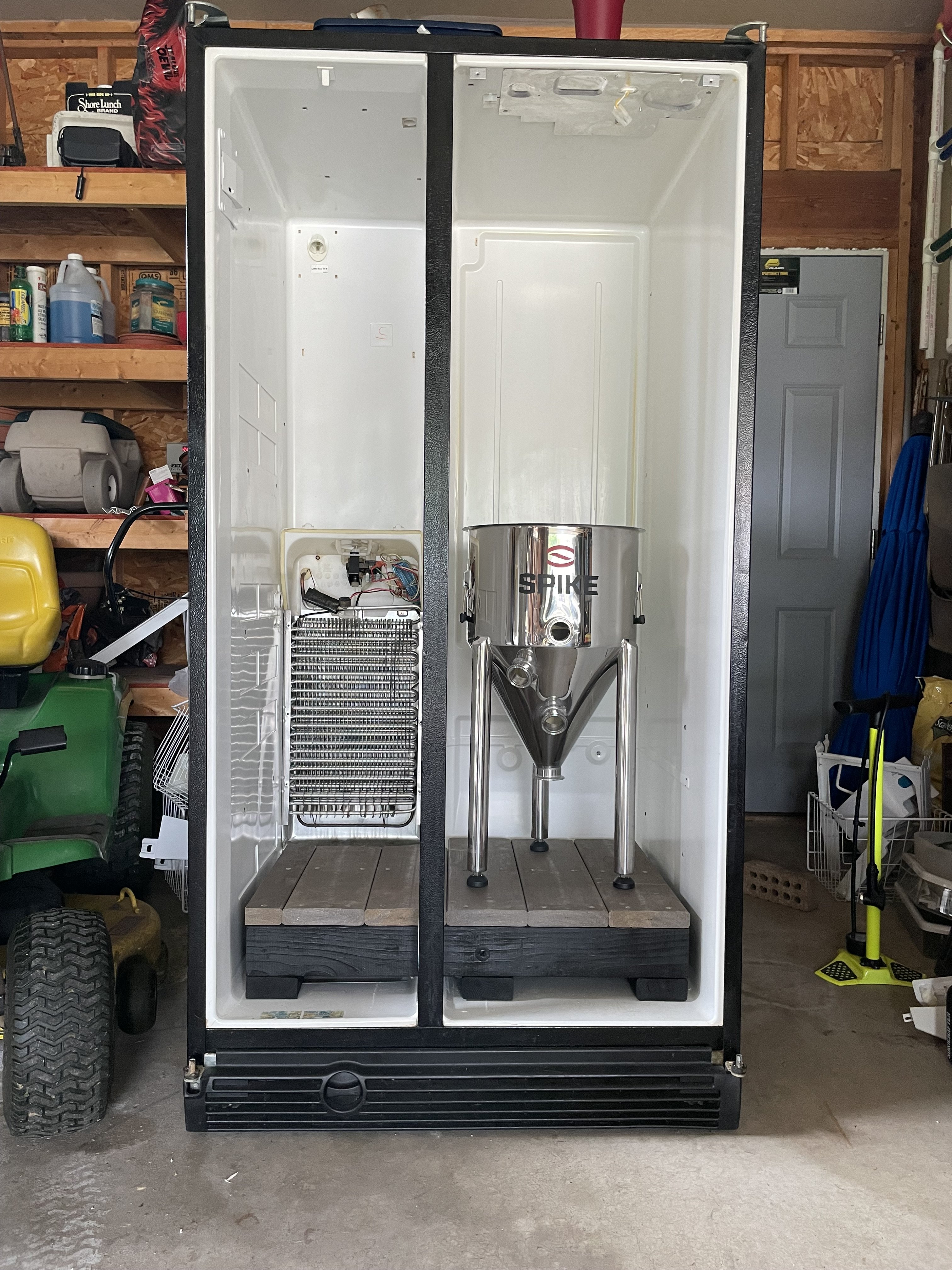
Time to cut the interior wall out! Used a multitool which worked very well. Mostly thin plastic and insulation, couple wire and compartments (venting) here and there.
tempImagec770I9.jpg

tempImageKlelZc.jpg

tempImagezf1iJm.jpg


Built a sturdy floor for the conical to sit on
tempImageM8NEzZ.jpg

tempImage0UuqLk.jpg


Now for the wiring. I simply removed the fridge thermostat and then cut and attached the 2 wires to a (SSR) solid state relay (which attached to my BrewPi controller).
tempImageCPywaK.jpg

tempImagehc7MAk.jpg


First test yesterday to see if it works. All good, YESSSS! Lights, fan, cooling!
tempImageMY6iUV.jpg


Very roomy for one, could probably fit 2 in there...
tempImagewKNn1a.jpg


tempImageRC5RL1.jpg


Still need to add the heat source and put a few things back in place but think it's going to work well.
I'll steal my light socket with reptile bulb for heat. It's only 40w and works great for my little wine fridge but might need 100w bulb for this beast.


I'm also trying to figure out how disable the auto defrost board as I'm never going to go below 32ºF. My understand is that if I don't disable the auto defrost, it may not allow cooling at times when the BrewPi calls for it.
If anyone knows more about this or if you know anything about bypassing this board, please let me know.

Here's a pic of the defrost board. Unfortunately, the only thing I know about this fridge is that it's a "Whirlpool Conquest". There are no stickers or wiring diagrams inside, outside or underneath.
tempImage3HzCba.jpg


Thanks for looking!!
Cheers.
 

Attachments

  • tempImageV7gd1v.jpg
    tempImageV7gd1v.jpg
    2.1 MB · Views: 0
  • tempImage6qGyyV.jpg
    tempImage6qGyyV.jpg
    1.7 MB · Views: 0
Last edited:
Very nice conversion. Looks like the defrost board has a relay. Do a test and bring the frig down to a colder temp. Put a meter across the relay. See if you can tell when the relay opens and closes. Maybe you can bypass the relay, or make a jumper to bypass the defrost board all together. Leaving the relay either in the open or closed position depending on your investigation.
 
Very nice conversion. Looks like the defrost board has a relay. Do a test and bring the frig down to a colder temp. Put a meter across the relay. See if you can tell when the relay opens and closes. Maybe you can bypass the relay, or make a jumper to bypass the defrost board all together. Leaving the relay either in the open or closed position depending on your investigation.
Thanks!
Any thoughts on bypassing the board all together (like you mentioned)? Is it possible to figure it out without a wiring diagram or can you tell how to bypass it based on the picture? I'm average at best understanding electronics and know I need to get around that board, but don't understand how.
 
@YeastFeast, On the relay it indicates 48 VDC, Do you have a multi-meter? Get your self some long wlre with alligator clips on each end. On the relay there is a diagram of the switch. It looks like pin 3 and 4 make up the switch. Put each alligator clip on pin 3 and 4, turn the board over and look to see if you can follow the copper board traces for pin 3 and 4. Put your meter on DC volts and close the frig door. turn the temp down and wait for the frig to trigger the defrost mode. Watch the meter.

You are waiting for normal mode when the frig is cooling. If the frig goes into defrost mode, the volts should either turn on or off. You will have to watch. If the defrost mode turns off the voltage, then one option is to jumper the switch so the voltage is on all the time. WIthout the circuit diagram it would be hard to troubleshoot how to bypass the board entirely.

If the voltage triggers off when in defrost mode then that would be a bit harder to work around unless you did more troubleshooting on the board. Would be tricky without much electronics knowledge. Do a search on google for a service repair manual of your frig. Many times there are diagrams and test procedures in the service manual.

Cheers

Joe
Joe, appreciate the detailed writeup. I do have a multimeter, just never used it for anything but testing batteries 😳. I'll give that a try! Got a friend helping me move the fridge from my garage to my basement later this afternoon/tonight so I'll see if I can figure out the relay on the board tomorrow.
 
@YeastFeast, also test out the frig with your BrewPi, There might be a chance that the defrost board is smart enough not to trigger if the temp never gets cold enough. Monitor your temp on your BrewPi, Check to see if the temp is controlled properly, according to your profile. If it maintains temp then, it is possible that the defrost board never is triggered.
 
@YeastFeast, also test out the frig with your BrewPi, There might be a chance that the defrost board is smart enough not to trigger if the temp never gets cold enough. Monitor your temp on your BrewPi, Check to see if the temp is controlled properly, according to your profile. If it maintains temp then, it is possible that the defrost board never is triggered.
Interesting thought and I was wondered just how "smart" these defrost boards are. My understanding is that before the defrost boards, refrigerators had defrost TIMERS which would just trigger after a certain amount of time no matter what. Maybe this thing won't trigger like you said?? Would have been a lot easier cutting out one of those timers than it is messing around with the whole board.
 
Model numbers lead to wiring diagrams. Module numbers are rarely that helpful.

Anyway, fwiw, most fridges use rather simple timers to trigger defrost cycles. And while a defrost cycle does perturb BrewPi fermentation control, I've found classic AVR version will eventually recover in a reasonable time without doing anything stupid. My two 17cf top-freezer fermentation fridges are "blessed" with auto-defrost and both clearly are timer based.

Also...I would not assume a chamber temperature above 32°F precludes freezing up an evaporator and the need for periodic defrosting. Fridges usually only know how to make air suitable for freezing stuff which immediately provides the mechanism for frosting an evap...

Cheers!
 
The board itself has a part number on it Whirlpool 2188159
Model numbers lead to wiring diagrams. Module numbers are rarely that helpful.
I did research the module number, unfortunately it lead me to find that that board can/is used in Amana, Estate, Kenmore, KitchenAid, Maytag, Roper, and Whirlpool refrigerator models.
 
Before I mess around much more I have some testing to do, may not have to do anything as @jpitz31& @day_trippr have alluded to....

...but I found this diagram earlier today. It looks to me like the "Electronic Defrost Control" portion matches the wire coloring/numbering from my board exactly.
I understand concepts but don't understand the diagram at all (as far as how to jump/reroute the wires) to bypass the defrost, hopefully I don't have to mess with it...

E3F008F1-4613-4834-BF6C-CDA0F7B7C173.jpeg

tempImageWimvMg.jpg
 
Last edited:
Also...I would not assume a chamber temperature above 32°F precludes freezing up an evaporator and the need for periodic defrosting. Fridges usually only know how to make air suitable for freezing stuff which immediately provides the mechanism for frosting an evap...

OK, so maybe I don't want to disable the defrost control if the evaporator is still going to freeze up with a chamber temp of say 40ºF or so?
I suppose BrewPi is going bring the temp of the chamber down much lower than the actual BrewPi beer temp setting to bring the beer down to the desired temp. In other words, if the beer is say 50ºF and I want it 35º, BrewPi may drop the chamber to 25ºF (or whatever) to get it there.
 
I would suggest leaving the auto defrost circuit/module intact. According to the circuit diagram provided above, I think you want to replace what is labeled as “thermostat” with the BrewPi. I am not familiar with BrewPi, but if it has a normally open contact, it should be an easy replacement.

Most modern and mid to high end (I would consider this one modern and mid to high end) defrost circuits that I have seen use temperature sensors on the cooling coils. Do you see any temperature sensors on the cooling coils that are wired to the ADC board?

From what I see in the ADC module picture, the chip, U1, is an 8 bit microcontroller from Microchip (PIC16C54). The microcontoller may/probably implements timer functions. Since this micro doesn’t have an internal analog to digital converter and since there isn’t another IC/chip on the ADC module, I doubt that you will find any temperature sensors on the cooling coils that are part of the ADC circuitry. Not that this information helps in any way.
 
I would suggest leaving the auto defrost circuit/module intact. According to the circuit diagram provided above, I think you want to replace what is labeled as “thermostat” with the BrewPi. I am not familiar with BrewPi, but if it has a normally open contact, it should be an easy replacement.

Most modern and mid to high end (I would consider this one modern and mid to high end) defrost circuits that I have seen use temperature sensors on the cooling coils. Do you see any temperature sensors on the cooling coils that are wired to the ADC board?

From what I see in the ADC module picture, the chip, U1, is an 8 bit microcontroller from Microchip (PIC16C54). The microcontoller may/probably implements timer functions. Since this micro doesn’t have an internal analog to digital converter and since there isn’t another IC/chip on the ADC module, I doubt that you will find any temperature sensors on the cooling coils that are part of the ADC circuitry.

Thanks for posting, after spending countless hours trying to figure out how to bypass the ADC board, I agree with you and a few others who posted that it probably makes the most sense to leave it alone. I can see how it would be very likely now that the BrewPi controller will take the chamber temp below freezing to get the beer temp down to say 40ºF (from 70ºF), therefore frosting/freezing the coils.
I plan on doing testing the next few days to see how it performs.

Not that this information helps in any way.
I found it very interesting and informative! Thanks.
 
OK, ran a quick first test tonight to see if everything was wired correctly. Filled the conical about 3/4 of the way up with water and let it rip.
Beer temp (in this case water) was 83ºF and I set BrewPi to set beer temp for 72ºF. Took about 1.5 hours to bring it to 71.7º. OK, that's good!

Now to see if the heater kicks in. 15 minutes later, heater does kick in but several hours later it's clear the 40w bulb is not sufficient in this MUCH larger space (than my old wine fridge) to bring temp back up if needed. The heater was clearly running but isn't putting out enough heat to bring it to the set temp.

I'm going to need a much bigger heat source...


tempImagepJpmtu.jpg


tempImage6qE2XN.jpg


tempImageu48ucO.jpg
 
Update: I upgraded the 40w heat lamp with a 150w version. Working good now! BrewPi has been maintaining set temperature for a day now within a tenth of a degree. I set up a profile today to raise the temp over a 2 day period from 68ºF to 72ºF. I'm guessing it will handle that just fine. Note: I'm testing with 3.5 gallons of water but I don't think that matters too much...the critical part is to make sure the cooling can bring the temp down to the set point and the heat can bring the temp up to the set point. With the 40w bulb, the software was never able to bring the temp up to the required setpoint as the volume of air was too large for the heat source. The 150w reptile bulb appears to be up to the task.
 
Last edited:
New feature. I added a window. I didn't want to open the doors every time I wanted to look at a gauge setting or to check out what was happening with blow off.

Found 2 old picture frames in the basement and took the glass from both of them. Then made a frame from a scrap 2x2 board. Cut (2) 1/4" groves in each board and painted it. Then slid the glass in and glued and screwed them together & added silicone around all edges. Finally I cut the hole in the side of the fridge and siliconed the window in. I also tapped into the right side door light wiring and added a light switch on the outside so I see.

Hopefully it doesn't steam up too much when I'm changing temps inside. We'll see.

tempImagedVs9ja.jpg


tempImage2XD1Vt.jpg


tempImagefJIIXu.jpg


tempImageYMvmtV.jpg


tempImagerrcmcg.jpg


tempImageQRpE9V.jpg
 
Back
Top