Schematic for electric RO system control - Sanity check?

Homebrew Talk - Beer, Wine, Mead, & Cider Brewing Discussion Forum

Help Support Homebrew Talk - Beer, Wine, Mead, & Cider Brewing Discussion Forum:

This site may earn a commission from merchant affiliate links, including eBay, Amazon, and others.

The_Bishop

Well-Known Member
Joined
Dec 8, 2013
Messages
2,100
Reaction score
676
I'm in the process of setting up my RO system to use a non-pressurized storage tank. I've come up with a high and low float switch setup using a relay and a latching circuit; it looks good to me but I'd like a second opinion and a sanity check.

My half-assed schematic is below. The idea is when the water level drops, the high switch enters the 'closed' position. This completes the 'ground' for the relay coil. When the water drops low enough, the low switch engages. This energizes the DPST relay coil, which switches the relay 'on'. Power is sent to the pump, and from the second relay terminal power is sent to the coil circuit, effectively 'latching' the relay closed so when the water level rises, the lower switch position doesn't matter any longer. When the water in the storage tank engages the top switch, it breaks the circuit for the relay coil which causes it to disengage and opens the relay.

Am I getting this right?

My apologies for the crappy diagram. Used tinycad to put it together.

pumpcontrol.png
 
I would think you would want the upper float switch to turn "off" the water once the float is pushed up and the lower switch to turn "on" the water flow once it goes low... This would prevent constant cycling in a system were large amounts are used at once.
 
Doug: Thanks!

Brundog: Yes, that's how I'll be installing them.

Augie: That's how it will be configured. When the water level rises to the upper float switch, it will open the relay coil circuit and cause the relay to 'open'. The lower switch will be oriented the same way, when the water level is at/above it, the circuit will be 'open'. There will be 17-18 gallons of hysteresis between cycles.

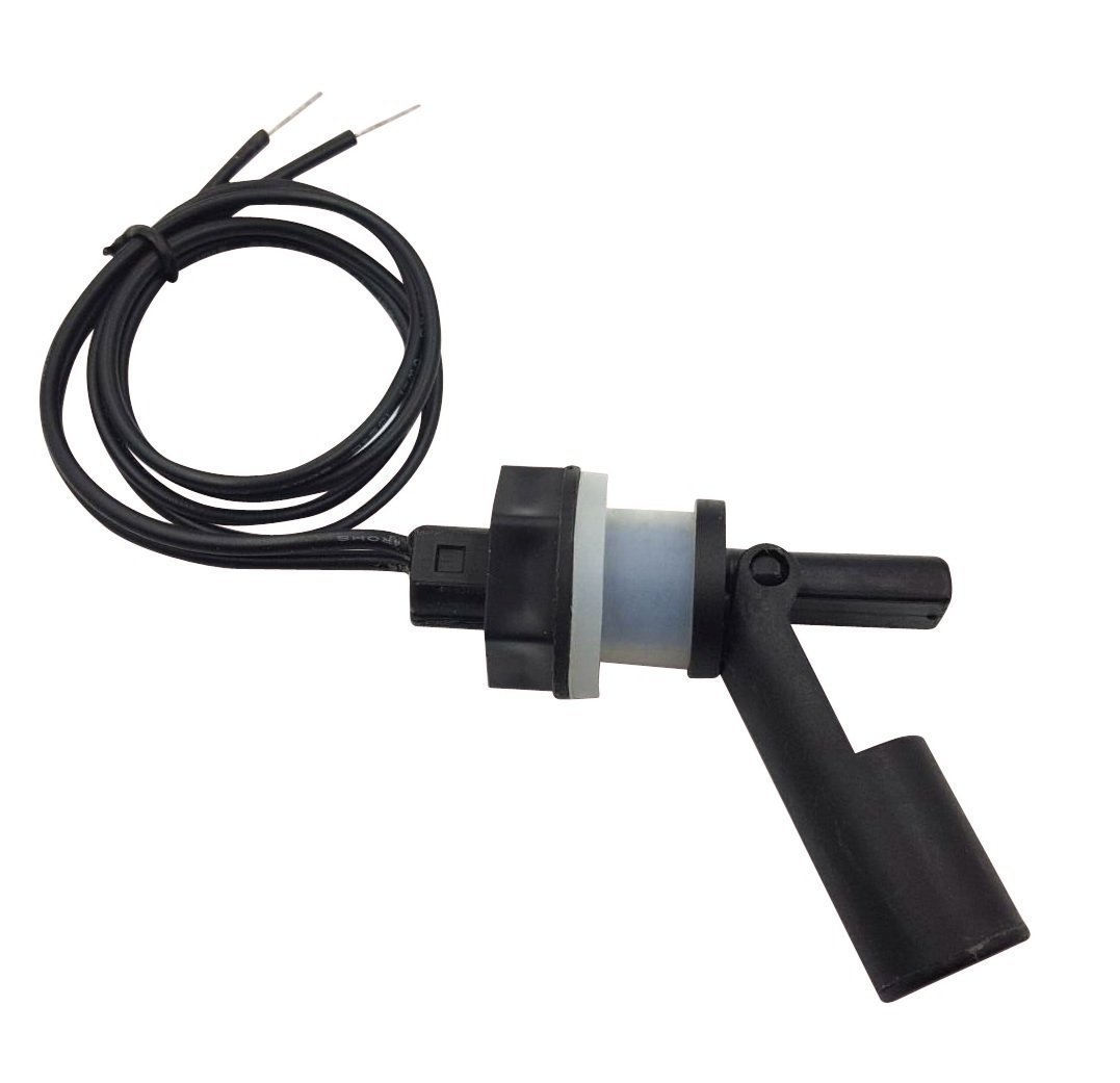
These are the float switches:

FS.jpg
 
Doug: Thanks!

Brundog: Yes, that's how I'll be installing them.

Augie: That's how it will be configured. When the water level rises to the upper float switch, it will open the relay coil circuit and cause the relay to 'open'. The lower switch will be oriented the same way, when the water level is at/above it, the circuit will be 'open'. There will be 17-18 gallons of hysteresis between cycles.

These are the float switches:
I tried using one of those same switches on my reef tank refuge toy replenish the gallon or so evap I get a day... it worked for a while but eventually failed electrically and in the closed position (electrically) causing my refuge to overfill...
I would try to plan for such a possible failure if possible... I could have just got a bad one as well but it worked for a few weeks..
 
I think you have your understanding of these switches incorrect. My bet is they are closed (electrically conducting) when the float is up (level above the switch). You need to confirm this first.

Edit: sorry, my understanding is incorrect! I see you can invert the state by inverting the mount direction!
 
Augie: What's not shown here is the tank's inlet (the permeate) will have a float valve on it to shut down the permeate flow and that line will have a pressure switch on it to shut things down if that happens. I'm hoping that by having a very minimal load (The relay coil) it will keep the float switches alive. What did you have connected to the float switch?

Brundog: Yeah, you can switch the operation of them merely by flipping them.
I had a very small aquarium pump (tiny with 3/8" hose connections) but honestly it was more than the 1 amp load these were meant to handle and may also have played into it.

I have used similiar 1 amp stainless floats to turn on and off my DC brew pumps directly when I had my autosparge setup going... Mainly though I use them to cut SSR control were the load is not a factor for my rims and HLT elements.
 
I saw that, just couldn't justify the idea of buying what I can build myself. It's a quirk I have.
 
I finally get around to putting this together and hit a snag.

I got a 24 volt DC relay.

Built and wired the box.

When I bench tested the box, hitting the conditions to trip on the relay resulted in the relay buzzing. I scratched my head a bit, went over the wiring again, then finally looked at the transformer for the booster pump.

Turns out the Aquatec stuff is 24 volts AC. Doh! I looked at the transformer, assumed (yeah, yeah... I know!) that meant DC and saw the voltage listed at 24. If I had looked a little closer I would have noticed the AC next to it.

The right relay should be arriving today. *sigh*

The water storage drum is all set up, added a dump valve for quickly filling buckets for brewing water, and a 3/8 inch push-to-connect fitting for the booster pump to deliver the water for upstairs use in the refrigerator and the separate tap in the sink. I was initially concerned with a 'breather' for the drum to allow air in and out as needed, and had come up with a few different things when Bobby at brewhardware.com suggested using the inline HEPA filters, which was a lot simpler than what I was considering. Thanks, Bobby!
 
We're up and running! It'll be nice to have 27-28 gallons of RO water ready to go.
 
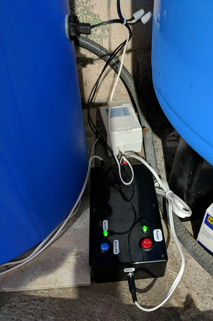
Here are a couple of pics of the new tank and the control box.

Tank.jpg


Control.jpg
 
If the failure of one of a float switches would have an adverse effect, like an overflow mess, you probably should add a second, hi-hi switch to trigger a shutdown of the system.

If your system is located outdoors or where a spill can be tolerated, then maybe no big deal.
 
There's a float valve on the permeate input to the tank along with a pressure triggered shutoff switch, so if the switches fail it will close the float valve which will shut the system down via the pressure switch.
 
Back
Top