Rebuilding Electric Brew Controller Questions

Homebrew Talk - Beer, Wine, Mead, & Cider Brewing Discussion Forum

Help Support Homebrew Talk - Beer, Wine, Mead, & Cider Brewing Discussion Forum:

This site may earn a commission from merchant affiliate links, including eBay, Amazon, and others.

adpostel

Supporting Member
HBT Supporter
Joined
May 3, 2013
Messages
102
Reaction score
24
I am redoing my single element brew controller. I have one 5500w 240v element. I want to use a single PID controller (Most likely Auber EzBoil) and I want to have 2 120v outlets controlled by switch.

My thoughts are to have one selector switch to power on the whole box.

Another selector switch to power on the element.

Two selector switches for the 120v outlets.

Do I need a 240v selector switch for the main power?

Do I need a 240v selector for the element?

Can I just use the 120v selector switches for the 120v outlets that would control the pumps?

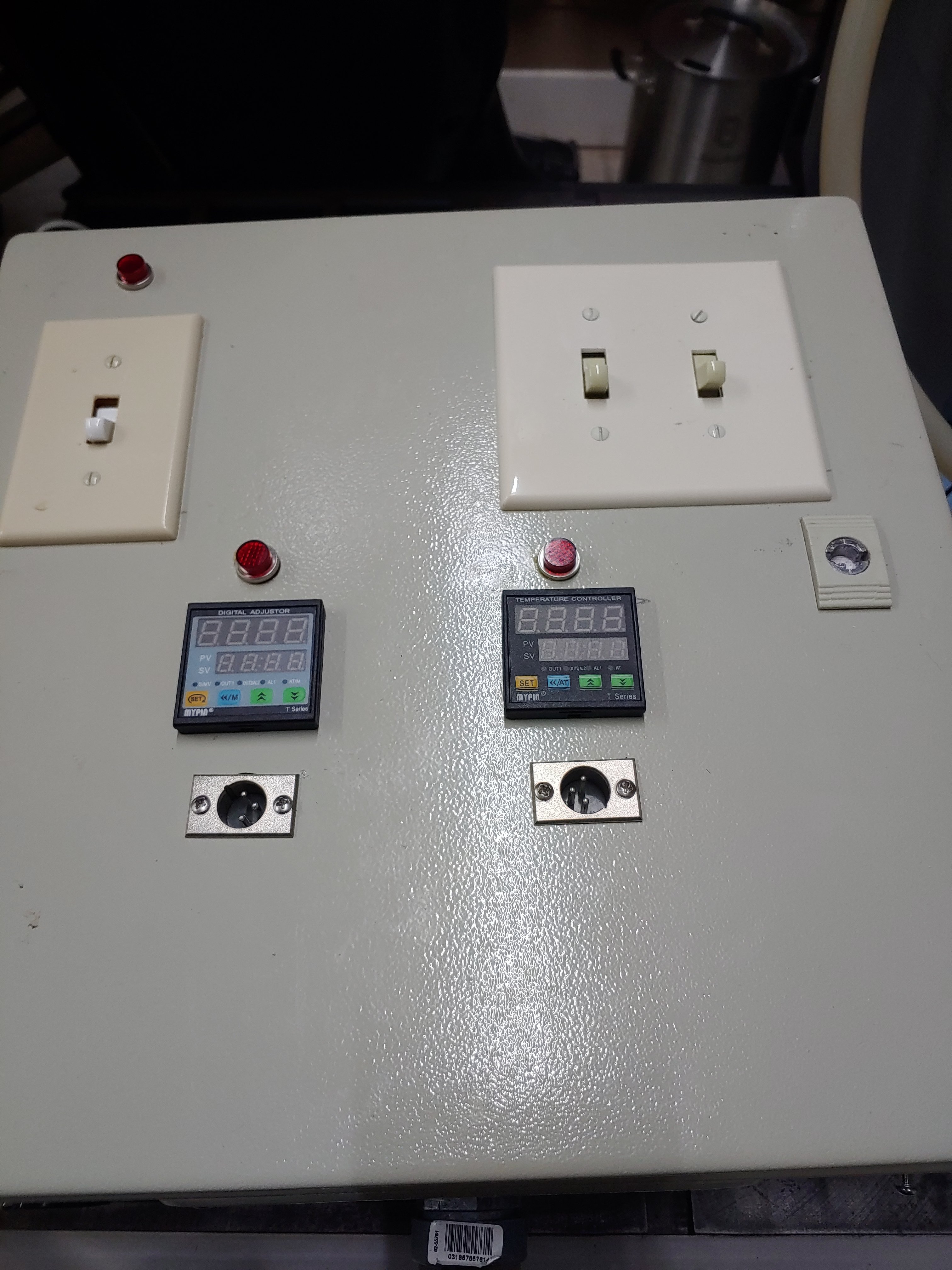
Trying to use what I already have, I have a control box now, but I'm trying to make it smaller and cleaner. It came with the EKettle I bought from a guy.
 
This is what the controller currently looks like....
 

Attachments

  • 1124200502.jpg
    1124200502.jpg
    1.3 MB · Views: 99
  • 1124200503_HDR.jpg
    1124200503_HDR.jpg
    1.8 MB · Views: 102
  • 1124200502a_HDR.jpg
    1124200502a_HDR.jpg
    1.5 MB · Views: 90
Wanting to do something similar to the Wort Hog but using LED selector switches.
I am trying to use as much of the items I currently have, but I realize I'm gonna have to buy a few things.
I already bought the new box. It's an 8x8x6 plastic enclosure.
 
Given what you want the new control box to have, about the only components you can reuse are the power connectors, and temp sensor connectors.

Here's a design that meets your requirements, as I understand them. The second 120V outlet circuitry is not shown, but is identical to the existing outlet.

DSPR300 2-Pump 1-Element 240V rev-2.PNG


Brew on :mug:
 
Cool... And the Main Power On switch doesn't have to be a key switch, right? Is there any benefit to using a key switch vs an LED selector switch?

Also, I was considering an E stop... Any pros or cons to having one?

Thank you so much for your help and advice!
 
Main power does not need to be a key switch, but must be a DPST-2NO in order for the "safe start" feature to work correctly. For a lighted switch, the hot side of the lamp connects to the left side of the switch in the drawing, and neutral to the right side. A key switch is an advantage if you have young children (or older ones who can't leave things alone.)

You can add an e-stop switch, but what's the point? You already have a switch in the same place that will kill all the power to the system. In industry, e-stops are located at places that operators are likely to be working, and at a distance from the main control panel. The e-stop would be an NC switch added between the left side of the main power switch and the main power contactor coil.

Brew on :mug:
 
Doug, for the contactors for the "main power on" switch and the "element" switch, should those contactors be 240v contactors? I think the diagram shows 120v 30 amp.... I'm just learning about all this wiring up, so just thought I'd ask.

EDIT: Ok, I think I answered my own question... the "Contactor" is a 30 amp contactor which is activated by a 120v coil.... and the 120v switch activates the coil, which closes the 30 amp contactor circuit... right?
Correct.

Brew on :mug:
 
Sorry, maybe too late to be of use, but others?

I take a different approach to heating element control. I use SCR voltage regulators and coil contactors instead of the popular PIDs and SSRs. The SCR knob adjusts the power level (voltage output) and the heating progress is monitored with 2 wireless temperature probes on the input and output of the RIMS tube. Intuitive and straight forward, though automatically setting an end point is not possible and the mash temperature needs to be manually monitored, at least the RIMS element can be set for a continuous gentle heat.

I believe only people with training should ever attempt to build their own control box!

Note in the design that the pump (outlet) must be on before the RIMS can be powered. I recently rebuilt and upgraded the control box and made a wiring diagram while I was at it, though have used this basic design for 3 years.

BTW, the RIMS tube (120v-1650watt) is used throughout the brew day. It helps the BK (240v-5500watt) heat the strike water, maintains and ramps the MT, does the mash out via pumping to the BK, and helps the BK bring the wort to a boil. A real time saver heating with 7150 watts. Currently waiting on a 2250 watt RIMS tube element replacement.


PowerControlBoxAug2020.pngRIMS-Pump_system2.jpg
 
Sorry, maybe too late to be of use, but others?

I take a different approach to heating element control. I use SCR voltage regulators and coil contactors instead of the popular PIDs and SSRs. The SCR knob adjusts the power level (voltage output) and the heating progress is monitored with 2 wireless temperature probes on the input and output of the RIMS tube. Intuitive and straight forward, though automatically setting an end point is not possible and the mash temperature needs to be manually monitored, at least the RIMS element can be set for a continuous gentle heat.

I believe only people with training should ever attempt to build their own control box!

Note in the design that the pump (outlet) must be on before the RIMS can be powered. I recently rebuilt and upgraded the control box and made a wiring diagram while I was at it, though have used this basic design for 3 years.

BTW, the RIMS tube (120v-1650watt) is used throughout the brew day. It helps the BK (240v-5500watt) heat the strike water, maintains and ramps the MT, does the mash out via pumping to the BK, and helps the BK bring the wort to a boil. A real time saver heating with 7150 watts. Currently waiting on a 2250 watt RIMS tube element replacement.


View attachment 721014View attachment 721015

My general comment on this is that while you described how you built your controller, i.e. that you use power controllers rather than temperature controllers, you never explain why. Are you suggesting that there is an advantage? While passive control with active human monitoring can work (obviously it works for you), it's so easy to use PID control that I don't get it. Even if you really like the granular nature of an SSVR, you can still build in temp control with a simple on/off temp controller on the SSVRs control line. I don't know if it's still being done that way but that's how the High Gravity controllers were first built.
 
My general comment on this is that while you described how you built your controller, i.e. that you use power controllers rather than temperature controllers, you never explain why. Are you suggesting that there is an advantage? While passive control with active human monitoring can work (obviously it works for you), it's so easy to use PID control that I don't get it. Even if you really like the granular nature of an SSVR, you can still build in temp control with a simple on/off temp controller on the SSVRs control line. I don't know if it's still being done that way but that's how the High Gravity controllers were first built.

I use to use PIDs and SSRs for the keg freezers and fermentation boxes but when I moved to the new house I purchased Inkbird controllers which though identical in operation, were just simpler to install and use. So 3 years ago when I upgraded to electric I decided a simple approach would be easier for the RIMS tube as well. The advantages are the simple analog dial control and the constant steady heat control of the element. At the time I had a concern about the element being at full power and scorching which turned out to not be a problem. Yes a PID can do this with fast cycles, but since I'm watching my brew anyway it's just as easy for me to simply dial in how much power is needed. Also, it's quick and easy to turn the power down during BK additions to avoid boil overs. There are PIDs with dials for power control as you probably already know. The BBQ wireless probes on my RIMS are the only temperature measurements needed during the brew day and can be monitor from anywhere around the house whereas PID probes don't easily do this. It just feels simple and easy.
 
So I noticed Doug's scheme shows a 4 wire 240v main power source. My current panel, and my current 240v outlet are only 3 wire. My brother is an electrician and told me that residential homes usually only carry the 3 wire Romex for the 240v. Is there a way that I can use my existing wiring and run the control box with the 3 wire Romex?
 
So I noticed Doug's scheme shows a 4 wire 240v main power source. My current panel, and my current 240v outlet are only 3 wire. My brother is an electrician and told me that residential homes usually only carry the 3 wire Romex for the 240v. Is there a way that I can use my existing wiring and run the control box with the 3 wire Romex?
To run both 240V and 120V loads (elements, pumps, etc.) from a control panel you need either:
  • Four wire power feed w/H-H-N-G, or
  • Two power feeds, one 240V and one 120V (two power input cords, plugged into two different circuits), or
  • A power transformer to reduce 240V to 120V
Brew on :mug:
 
OK, thats what my brother said, he mentioned a power transformer would be the easiest way with what I currently have going on. My question is my current PID is 120v powered, right? so how is that being done?
 
OK, thats what my brother said, he mentioned a power transformer would be the easiest way with what I currently have going on. My question is my current PID is 120v powered, right? so how is that being done?
Most all modern PID's will work on either 120V or 240V.

Brew on :mug:
 
To run both 240V and 120V loads (elements, pumps, etc.) from a control panel you need either:
  • Four wire power feed w/H-H-N-G, or
  • Two power feeds, one 240V and one 120V (two power input cords, plugged into two different circuits), or
  • A power transformer to reduce 240V to 120V
Brew on :mug:

Could you please show me a step down transformer that could go wired inside my control box? I am only seeing plug in ones on Google....
 
Could you please show me a step down transformer that could go wired inside my control box? I am only seeing plug in ones on Google....
I haven't done any designs with step down transformers, so don't have any idea what is currently available and suitable.

Personally, I would look at just not controlling the pumps from the heating control panel. Then you don't need any 120V in the control box, so a three wire power feed is fine.

Brew on :mug:

My brother is gonna come run me a fourth wire to the sub panel so it will be done the right way. After looking closely at all the other builds, they all have the 4 wire setup. So he will come install it next weekend. Thank you for all of your patience and answers. I have everything to put the new control box together and I just want to do it the right way.
 
My brother is gonna come run me a fourth wire to the sub panel so it will be done the right way. After looking closely at all the other builds, they all have the 4 wire setup. So he will come install it next weekend. Thank you for all of your patience and answers. I have everything to put the new control box together and I just want to do it the right way.
This is the best option.

Brew on :mug:
 
OK, doug293cz, I changed routes just a bit. I decided to not control my pumps from my control panel. I decided to stay with the three wire setup that is already ran and working fine. I will just plug the pumps up to a separate 120v outlet on the wall, no big deal. So that leaves me with a very simple control panel for my heating element. So here is what I have come up with and I was hoping you could redo a diagram using these parts.

I am going with a 32 amp dual pole breaker style switch with a LED indicator light for main power.

one 240v LED switch for my element on/off and a small red firing lamp

I have a 240v contactor switch if I need it, but I'm going with a small box, so if I don't have to use the contactor switch, I'm good without it.

Auber EZboil PID 320

40amp SSR


Very simple setup, and its currently all I'm using on my current setup anyway.

My brother is fashioning a small two outlet box with outlets in the back and switches in the front that will plug into a separate outlet on the wall for the pumps.

Thank you...
I no longer accept design requests of the type: "I bought these specific components, can you do a design for me that uses them?" I do designs which I believe will have applicability to multiple brewers, using components that I know will work, and I believe are "best in class." For example, I only design with EZBoil DSPRxxx controllers, as I believe these are better (for reasons I have stated several times in multiple threads.) Anyone is free to substitute another controller if they wish, but it is up to them to figure out the required design modifications needed to get it to work. Same with other components in my designs.

Here is a design that uses three wire (H-H-G) power input, and controls a single element:

DSPR120 1-Element  240V only.PNG


You would substitute your 32A breaker/switch for the Leviton 3032 switch. The DSPR320 wires up the same way as the DSPR120 shown. The front panel of the DSPR will act as your power on indicator, but as designed, the DSPR will be on as soon as the power is connected. You could add a switch to control power to the DSPR, but then you set up the possibility of having the element power enabled before the DSPR is powered on. This is likely to cause the element to turn on as soon as the DSPR is powered up, which will be a problem if the element is not yet covered with water/wort.

Brew on :mug:
 
Back
Top