• Please visit and share your knowledge at our sister communities:
  • If you have not, please join our official Homebrewing Facebook Group!

    Homebrewing Facebook Group

Rebuilding - Again...

Homebrew Talk

Help Support Homebrew Talk:

This site may earn a commission from merchant affiliate links, including eBay, Amazon, and others.
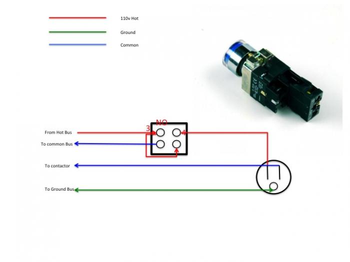
Attached is a quick diagram, very simple i might add, of how i THINK i should wire the LED NO maintained pushbutton switch.

Can you guys look at it and tell if it is correct, and if not where I went wrong.
My diagram that came with the kit, has separate switches and less on it, so i want to make sure I have it correct.

Tim

Switch Wire diagram.jpg
 
you can always check it with a multimeter for continuity? I dont think you should need any jumperwires if the switch is designed to be illuminated... you just need a neutral or second hot input if its 220....
 
The switch is a maintained pushbutton, and if I have it wired right, the led should only come on when the circuit is closed and providing power to the pump outlet. That is why I have the jumper.

Tim


Sent from my iPad using Home Brew
 
MX1, you actually need to have your jumper coming from what looks like what you have labeled as pin 4 if you want the LEDto only be illuminated when the button it depressed, I.e. When your pump is running/getting power.

As you have it now, your hot bus is active at all times, so it keeps the LED lit; you want to tie the element into the switched side that is normally powered off.

:mug:
 
So i wish I had any progress to add to this thread, but I have decided that I nned to pay someone to wire my control box, i just do not have the balls to do it myself
 
Probably shouldn't take an electrician too long to do, as long as he has a diagram. Most of the effort is stripping wires, tidying them up, crimping connectors.

You can do it with some basic testing with a multimeter. You could even post pictures here. When I assembled my box (1 pid, 1 contactor, 2 way switch, ssr, led status light, switches for pid/pump/fan) I tested things in phases, as I built the box. Less intimidating than wiring everything up and throwing the master switch. :D
 
I found it was easier to break up the wiring into smaller chunks, i.e. Master power, element power and switch, PID-SSR, PID alarm and switch. Made it a little less intimidating than the finished mess of wires would suggest. Only took me a week to wire, but cutting holes took a couple of weekends, square holes are a bitch.


Sent from my iPhone using Home Brew
 
By the way the first time I threw the switch the GFI popped immediately, I knew I wired the control box right but couldn't figure it out, after an hour of testing turned out my EE buddy had wired the GFI in the main box wrong.


Sent from my iPhone using Home Brew
 
If anyones overwhelmed by the electrical side of things, here's the order I wired and tested things;

- Install the components in the box itself (ssr, contactor, etc.). When your doing the layout, think about whats going to be connected to what. There should be a flow. For example, there should be a natural layout from the block terminals to the ssr, to the contactor then to the element. Make sure their not all over the place.
- Install plastic tie downs for cable ties in areas you'll run wiring, around the componants. I run wiring through the cable ties loosly, so changes can be made.
-For testing (*not* the element), you can cut the female plug side of a cheap extension chord, connect the + and - wires to to the respective block terminals, and plug in when needed. This will let you test everything UP TO the element (so don't wire the element).
- If you have a low power transformer (for 12v pumps, fans, etc...) wire those first.
- Wire the thermocouple, pump, pid, ssr, contactor, fuses, etc.
- Install and wire the componants on the outside (lights, pid, switches)
- Do a visual to make sure everythings wired right.
- When ready plug your 120v extension chord into a gfci outlet. If there's an issue the gfci should trip, potentially saving componants from frying out.
- Test all componants
- When ready and comfortable, run the two lines (aka two hots) from the terminal blocks to the contactor, then to the elements.
- At this point its time to wire the box to a 220v source.

Hope this helps someone. This is _one_ way to do it, but by breaking down the steps like this you'll catch things sooner and possibly do less damage.

Everyone should know how to use a multimeter to test for both 120 and 240 voltage, not to mention DC if your working with that. Basic skills. Knowing this will let you test the power coming in to verify everythings working right.
 
Ok, found someone to finish the control box for me, so that is good.
Started painting the brew stand, so I can get the pumps and stuff mounted.

Should be able to build the element cables and get them wired up this week as well.

Next week, dry run, and last parts order, so the brew side of the house should be done then on to the fermentation side.

Tim
 
Thanks! Looking forward to seeing the finished product! Its nice to see a build project that explains the different steps and seeing the input from other people.
 
Making a little bit of progress. Installed the rubber mat. Made a connection hose, figured out my pump layout as well.
Ordered a few more small things the found out I don't need them...if I don't mess up I will have 2 sets of vinyl sight glass markings up for grabs.
Also realised that I am short 1 F cam lock, I hate ordering something like that and paying shipping that will turn out to be more than the part....

10453704_1501625706733744_1310905303_n.jpg
 
On further inspection and thought, I am missing the cams I need to connect my CFC.

I did get the cams I was missing for my pumps, also some T's for the temp probes.

I will sit down and get a finial parts list done this weekend, and I hope to be brewing by AUG.

Update on the control panel...contractor 1 after having it for 2 weeks called and said they did nothave time to look at it.

contractor 2, looked at it yesterday and said it wold be ready by next Friday....

Tim
 
Did the auto tune/wet test this morning. Few leaks to fix but everything else went well.

Picked up a 7 cf keezer fridge will fit 4 pin locks with a collar for $125 yesterday. Right now on my way home with a 22 cf fridge that will let me put both fermenters side by side CL special for $75. Now to sell my mini fridge and order a 3 tap set up instead of a 2 tap.
 
The panel looks pretty nice. What did they charge to wire it up for you?

Looks like things are moving forward!
 
$170,

Estimated 2 hours for the job, quoted me no more than $170

Took him over 6 to do the job

Tim


Sent from my iPad using Home Brew
 

Latest posts

Back
Top