If anyones overwhelmed by the electrical side of things, here's the order I wired and tested things;
- Install the components in the box itself (ssr, contactor, etc.). When your doing the layout, think about whats going to be connected to what. There should be a flow. For example, there should be a natural layout from the block terminals to the ssr, to the contactor then to the element. Make sure their not all over the place.
- Install plastic tie downs for cable ties in areas you'll run wiring, around the componants. I run wiring through the cable ties loosly, so changes can be made.
-For testing (*not* the element), you can cut the female plug side of a cheap extension chord, connect the + and - wires to to the respective block terminals, and plug in when needed. This will let you test everything UP TO the element (so don't wire the element).
- If you have a low power transformer (for 12v pumps, fans, etc...) wire those first.
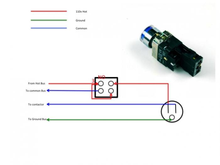
- Wire the thermocouple, pump, pid, ssr, contactor, fuses, etc.
- Install and wire the componants on the outside (lights, pid, switches)
- Do a visual to make sure everythings wired right.
- When ready plug your 120v extension chord into a gfci outlet. If there's an issue the gfci should trip, potentially saving componants from frying out.
- Test all componants
- When ready and comfortable, run the two lines (aka two hots) from the terminal blocks to the contactor, then to the elements.
- At this point its time to wire the box to a 220v source.
Hope this helps someone. This is _one_ way to do it, but by breaking down the steps like this you'll catch things sooner and possibly do less damage.
Everyone should know how to use a multimeter to test for both 120 and 240 voltage, not to mention DC if your working with that. Basic skills. Knowing this will let you test the power coming in to verify everythings working right.


![Craft A Brew - Safale S-04 Dry Yeast - Fermentis - English Ale Dry Yeast - For English and American Ales and Hard Apple Ciders - Ingredients for Home Brewing - Beer Making Supplies - [1 Pack]](https://m.media-amazon.com/images/I/41fVGNh6JfL._SL500_.jpg)


