bjhbrew
Well-Known Member
- Joined
- Oct 15, 2016
- Messages
- 159
- Reaction score
- 90
Hey folks,
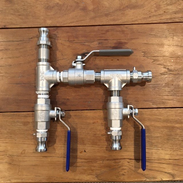
I guess the title more or less says it; I'm wanting to add a section of hard plumbing that allows me to flip a couple valves and run my wort post boil through my counter flow chiller to cool and then bypass the chiller at the end for whirlpool. I find that my chiller is quite restrictive otherwise I'd probably just leave it in the loop the whole time. So, using some parts I already had in my bin this is what I came up with:

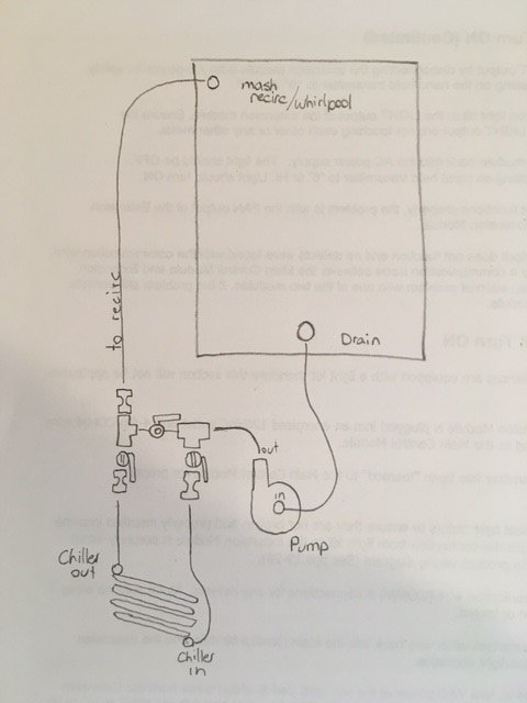
And a little drawing of how it would hook in with the rest of my EBIAB kettle:

I end up with a bunch of short silicone hose runs but I'm pretty sure this will work and It would be pretty easy to mount on my brew stand as well as prime/drain etc. I had a couple questions and hoped someone who has done something similar could help me out.
The main thing I'm wondering is whether or not I still need a ball valve on the output of the pump? If I go with a short section of silicone hose to connect from the pump to this manifold I could throttle the flow on the manifold but I guess that means the silicone hose will always be pressurized. Is this going to cause the hose to eventually pop? I like to disassemble my pump after most brew days so I don't think I want to hard mount to the pump (plus I don't think I know how anyways Honestly, my main motivation for not having a ball valve on the pump outlet is that I can never seem to thread one on and get it tight enough to not leak but have the handle facing the right way; if I could just crank down a camlock that'd be great! Does anyone have tips for putting together threaded fittings and having it line up the way you want? Is it a certain number of teflon tape wraps? Maybe I unlucky but they always seem to tighen up 180 from where I want them haha.
I guess the title more or less says it; I'm wanting to add a section of hard plumbing that allows me to flip a couple valves and run my wort post boil through my counter flow chiller to cool and then bypass the chiller at the end for whirlpool. I find that my chiller is quite restrictive otherwise I'd probably just leave it in the loop the whole time. So, using some parts I already had in my bin this is what I came up with:

And a little drawing of how it would hook in with the rest of my EBIAB kettle:

I end up with a bunch of short silicone hose runs but I'm pretty sure this will work and It would be pretty easy to mount on my brew stand as well as prime/drain etc. I had a couple questions and hoped someone who has done something similar could help me out.
The main thing I'm wondering is whether or not I still need a ball valve on the output of the pump? If I go with a short section of silicone hose to connect from the pump to this manifold I could throttle the flow on the manifold but I guess that means the silicone hose will always be pressurized. Is this going to cause the hose to eventually pop? I like to disassemble my pump after most brew days so I don't think I want to hard mount to the pump (plus I don't think I know how anyways


![Craft A Brew - Safale S-04 Dry Yeast - Fermentis - English Ale Dry Yeast - For English and American Ales and Hard Apple Ciders - Ingredients for Home Brewing - Beer Making Supplies - [1 Pack]](https://m.media-amazon.com/images/I/41fVGNh6JfL._SL500_.jpg)


