• Please visit and share your knowledge at our sister communities:
  • If you have not, please join our official Homebrewing Facebook Group!

    Homebrewing Facebook Group

PID settings on arduino based hlt

Homebrew Talk

Help Support Homebrew Talk:

This site may earn a commission from merchant affiliate links, including eBay, Amazon, and others.

SimBrew

Well-Known Member
Joined
Dec 19, 2010
Messages
86
Reaction score
0
Location
Montréal
I got a arduino controlled hlt with 1500w element heating like 5 gal.

I overshoot my setpoint by about 10 F.

The integral is too slow to shut the element off once it get to the setpoint

My process class are far away and I don't have a lot of time with the kid to test differents settings.

What are your PID settings on setup like mine ?
 
SimBrew said:
I will try for sure.
Would you happen to have your autotune code ?

I'm pretty sure I do. It's the same as what's right there on the site, though, with two minor exceptions.

- I added what I needed to get a Fahrenheit setpoint and readout in the serial monitor from a DS18B20

- I did a cut & paste swap of the part from the 'to control a relay' example, also located on that site.

I have *not* been successful getting the front end up in Processing, though. I just opened up a serial monitor in the Arduino IDE.
 
FOREVER! Or so it seems. Maybe 6 heat/cool cycles? In my crockpot, that must have been a couple of hours or so.

I watched Hudson Hawk while it ran.
 
Oh... if this is obvious, forgive me for bringing it up.

Watch that last line just before void setup(), it will run a simulation until you change that value to false.
 
FOREVER! Or so it seems. Maybe 6 heat/cool cycles? In my crockpot, that must have been a couple of hours or so.

I watched Hudson Hawk while it ran.

Thanks. I tried running it last night on my brewery and it about 2 hours for it to get to the setpoint once. My setpoint is at 154. The output would only go to 50. I will look at my code and try running it again tonight.

When I first ran i had it in simulation mode as you said and took me a couple of minutes to find the line to change it to tuning mode.
 
The integral is too slow to shut the element off once it get to the setpoint

This is a slow, integrating temperature loop. You don't want a lot of integral gain in this type of loop, because it will cause unnecessary controller windup.
Integral is not going to do anything at setpoint. More derivative can help to decrease overshoot. In fact, more proportional will help get your output high enough when you are far from setpoint but bring it down as you approach setpoint.

All of these suggestion are assuming your heating element is appropriately sized.
 
TO chuckjaxfl:

Do you mind sharing your code. I cant get the auto tune portion to work. I don't have a problem reading temperatures and even have the arduino send outputs to processing but cant seem to get the auto tune to work correctly.

Thanks in Advance.
 
Edited per the post below. Thanks for the tip!

Code:
#include <PID_v1.h>
#include <PID_AutoTune_v0.h>

#include <OneWire.h>
int DS18S20_Pin = 8; //DS18S20 Signal pin on digital 8
//Temperature chip i/o
OneWire ds(DS18S20_Pin); // on digital pin 8

#define RelayPin 3
int relayPin = 3;
int WindowSize = 1000;
unsigned long windowStartTime;


byte ATuneModeRemember=2;
double input=80, output=50, setpoint=100;
double kp=2,ki=0.5,kd=2;

double kpmodel=1.5, taup=100, theta[50];
double outputStart=5;
double aTuneStep=500, aTuneNoise=1, aTuneStartValue=500;
unsigned int aTuneLookBack=200;

boolean tuning = true;
unsigned long  modelTime, serialTime;

PID myPID(&input, &output, &setpoint,kp,ki,kd, DIRECT);
PID_ATune aTune(&input, &output);

//set to false to connect to the real world
boolean useSimulation = false;

void setup()
{
  //Setup the pid 
  myPID.SetOutputLimits(0, WindowSize);
  myPID.SetMode(AUTOMATIC);


  if(useSimulation)
  {
    for(byte i=0;i<50;i++)
    {
      theta[i]=outputStart;
    }
    modelTime = 0;
  }

  if(tuning)
  {
    tuning=false;
    changeAutoTune();
    tuning=true;
  }
  
  serialTime = 0;
  Serial.begin(9600);
  
  windowStartTime = millis(); //from pid test Relay
  pinMode(RelayPin,OUTPUT);  //from pid test Relay

}

void loop()
{

 unsigned long now = millis();
 float temperature = getTemp();
 float tempF = temperature * 9/5 + 32;

  if(!useSimulation)
  { //pull the input in from the real world
    input = tempF;
  }
  
  if(tuning)
  {
    byte val = (aTune.Runtime());
    if (val!=0)
    {
      tuning = false;
    }
    if(!tuning)
    { //we're done, set the tuning parameters
      kp = aTune.GetKp();
      ki = aTune.GetKi();
      kd = aTune.GetKd();
      myPID.SetTunings(kp,ki,kd);
      AutoTuneHelper(false);
    }
  }
  else myPID.Compute();
  
  if(useSimulation)
  {
    theta[30]=output;
    if(now>=modelTime)
    {
      modelTime +=100; 
      DoModel();
    }
  }
  else
  {
 //    analogWrite(0,output); // commented out by me
   unsigned long now = millis();
  if(now - windowStartTime>WindowSize)
  { //time to shift the Relay Window
    windowStartTime += WindowSize;
  }
  if(output > now - windowStartTime) digitalWrite(RelayPin,HIGH);
  else digitalWrite(RelayPin,LOW);
  }
  
  //send-receive with processing if it's time
  if(millis()>serialTime)
  {
    SerialReceive();
    SerialSend();
    serialTime+=1000;
  }
}

void changeAutoTune()
{
 if(!tuning)
  {
    //Set the output to the desired starting frequency.
    output=aTuneStartValue;
    aTune.SetNoiseBand(aTuneNoise);
    aTune.SetOutputStep(aTuneStep);
    aTune.SetLookbackSec((int)aTuneLookBack);
    AutoTuneHelper(true);
    tuning = true;
  }
  else
  { //cancel autotune
    aTune.Cancel();
    tuning = false;
    AutoTuneHelper(false);
  }
}

void AutoTuneHelper(boolean start)
{
  if(start)
    ATuneModeRemember = myPID.GetMode();
  else
    myPID.SetMode(ATuneModeRemember);
}


void SerialSend()
{
Serial.print("setpoint: ");Serial.print(setpoint); Serial.print(" ");
Serial.print("input: ");Serial.print(input); Serial.print(" ");
Serial.print("output: ");Serial.print(output); Serial.print(" ");
  if(tuning){
Serial.println(" tuning mode ");
//    Serial.print("kp: ");Serial.print(myPID.GetKp());Serial.print(" ");
//    Serial.print("ki: ");Serial.print(myPID.GetKi());Serial.print(" ");
//    Serial.print("kd: ");Serial.print(myPID.GetKd());Serial.println();
  } else {
    Serial.print("kp: ");Serial.print(myPID.GetKp());Serial.print(" ");
    Serial.print("ki: ");Serial.print(myPID.GetKi());Serial.print(" ");
    Serial.print("kd: ");Serial.print(myPID.GetKd());Serial.println();
  }
}

void SerialReceive()
{
  if(Serial.available())
  {
   char b = Serial.read(); 
   Serial.flush(); 
   if((b=='1' && !tuning) || (b!='1' && tuning))changeAutoTune();
  }
}

void DoModel()
{
  //cycle the dead time
  for(byte i=0;i<49;i++)
  {
    theta[i] = theta[i+1];
  }
  //compute the input
  input = (kpmodel / taup) *(theta[0]-outputStart) + input*(1-1/taup) + ((float)random(-10,10))/100;

}

float getTemp(){
 //returns the temperature from one DS18S20 in DEG Celsius

 byte data[12];
 byte addr[8];

 if ( !ds.search(addr)) {
   //no more sensors on chain, reset search
   ds.reset_search();
   return -1000;
 }

 if ( OneWire::crc8( addr, 7) != addr[7]) {
   Serial.println("CRC is not valid!");
   return -1000;
 }

 if ( addr[0] != 0x10 && addr[0] != 0x28) {
   Serial.print("Device is not recognized");
   return -1000;
 }

 ds.reset();
 ds.select(addr);
 ds.write(0x44,1); // start conversion, with parasite power on at the end

 byte present = ds.reset();
 ds.select(addr);  
 ds.write(0xBE); // Read Scratchpad

 
 for (int i = 0; i < 9; i++) { // we need 9 bytes
  data[i] = ds.read();
 }
 
 ds.reset_search();
 
 byte MSB = data[1];
 byte LSB = data[0];

 float tempRead = ((MSB << 8) | LSB); //using two's compliment
 float TemperatureSum = tempRead / 16;
 
 return TemperatureSum;
 
}
 
I hope it's helpful!

I'm not a programmer, so if it looks butchered it's because I'm pretty new to Aruidino. Like I said in another post, the last thing I wrote was in "Clipper" for dBase III.
 
I like that some code is starting to show up in this forum!

FYI- You might want to wrap that code using the [ CODE ] [ /CODE ] tags (the # button under advanced). I believe it will make it easier to copy/paste.

Code:
Example of wrapped code
line 1
line 2
line 3
 
I hope it's helpful!

I'm not a programmer, so if it looks butchered it's because I'm pretty new to Aruidino. Like I said in another post, the last thing I wrote was in "Clipper" for dBase III.

Thanks Chuckjaxfl. No worries on the code. I am a hack when it comes to programming as well. I won't be able to try it out until Thursday.
 
Where did you get your ds18b20 probe, or did you build your own? Also, can you describe how you will mount it in your hlt or on the outlet of the hlt? For example, are you using a compression fitting and a T fitting?

-jbrew
 
Where did you get your ds18b20 probe, or did you build your own? Also, can you describe how you will mount it in your hlt or on the outlet of the hlt? For example, are you using a compression fitting and a T fitting?

-jbrew

I got my sensors at Sensors

I got my thermowell from Auberins ThermoWell I took connector off and pulled the thermocouple out then ran a drillbit through the it and the DS1820 probes fit great.
 
Where did you get your ds18b20 probe, or did you build your own?

Give www.brewershardware.com a look if you're looking for DS18B20 sensors (listed under "BrewTroller" sensors). His are pretty top notch.

I used his probe ends but put together my own sensors with a right-angle M12 connector on the end of them. I really like this setup better than any others I've had in the past.

M12_Probe1.jpg


M12_Probe2.jpg
 
Hopefully, I'll have better answers for you guys today. I'm working on it today.

The part that is pertinent to this thread is that I changed the Serial.print parts to work on the LCD (no biggie), and I changed a couple lines in the working code. Specifically, I changed the aTuneStep to 200, and the aTuneStartValue to 250. I'm hoping this will bring the rise & fall of the autotune to a reasonable rate, instead of the huge spike and the take-forever fall I experienced before.

I'll let you know how it goes.
 
chuckjaxfl said:
Hopefully, I'll have better answers for you guys today. I'm working on it today.

The part that is pertinent to this thread is that I changed the Serial.print parts to work on the LCD (no biggie), and I changed a couple lines in the working code. Specifically, I changed the aTuneStep to 200, and the aTuneStartValue to 250. I'm hoping this will bring the rise & fall of the autotune to a reasonable rate, instead of the huge spike and the take-forever fall I experienced before.

I'll let you know how it goes.

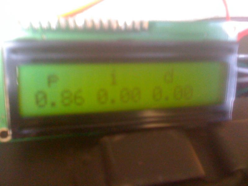
Okay, this went over like a fart in church.

I guess the numbers will work, eventually! I have hard time accepting that my PID should just be a P with no ID.

I'd try it, throw some more cold water in and see, but something just quit working in the can, so I'll have to fix that first.

Frustrating DIY day.

image-2676334983.jpg
 
It's official... I'm no help.

The autotune library continues to give me values similar to the above for P.. and zeros for I & D.

I spent some time last night reading about PID loop tuning. I'm going to post in the DIY section and see if I can get some help.
 
Hey Chuck!!!
Any results on the I and D numbers yet? You know I am watching to sneak a peak at where you end up too. I am using the REX C-100's and have been hard at assembling the rest of the circuit boards and relays to support this system. I decided to learn C and went with the PIC 16f877A 40 pin chip for a developement and prototype of the system. Keep us up with your results please..
Wheelchair Bob
 
No... I'm close to giving up the faith on the autotune. I'm really frustrated with it.

The only idea I have right now is to drag my the Arduino IDE, my sketches, etc, and everything over to my windows laptop so I can drag my laptop out to the garage. I'll have to tolerate using Windows, but that will at least allow me to make modifications on the fly using the Processing front end, if I can get that up and running. I'll have to rebuild my PCB on a breadboard, too, so I can use my Arduino Nano to get speak to the laptop. As it is, I'm pulling the chip from my homemade PCB, bringing it into the house and installing it into my UNO... writing a change to it, then carrying it back out and reinstalling it. It's a pain in the butt, and make me wish I'd installed a ZIF socket on my PCB because the pins are getting worn out.

Then I guess I'm going to have to use Processing to adjust the tuning manually. I'm reading a lot about it. So far, it looks pretty unachievable. There are a few methods. The one with the most data available (Ziegler-Nichols) appears to allow overshoot, and stabilizes in "a few cycles" which, for us, may be 1/2 through a brew session. There's another method (Labmda) that appears to work like my Auber pids (nice ramp up to temp with little-no overshoot), but the information that is available assumes you are a controls engineer and already understand all the terms.

I'm also considering "cheating", hooking up my Auber PID, running autotune with it, and copying the parameters over. But, I tried that when I was working with the crockpot, and settings for one controller don't equal the settings in another. For instance, the "I" may mean "resets per second" for one, and "seconds per reset" in the other. Same with "D".

It all makes me want to give up and just put the damn Auber PID in there.

In any case, I'm sorry to the OP for hijacking your thread. I think, though, that my solution will also be your solution.
 
Looks like the auto tune is trying to guestimate using the Ziegler-Nichols method (increase P till the system oscillates, then fix P,I,D based on some simple approximations). It might be easier just to do it yourselves.

http://en.wikipedia.org/wiki/PID_controller#Ziegler.E2.80.93Nichols_method

Or, just make your own PWM based control based on the temp differential and a certain K factor
 
Marc,
The Wiki on PID's was outstanding. That was a very timely link and an even better explanation. Sometimes WIKI goes over my head, but this one made enough sense that I could follow most of it and it really helped me understand the concept of wind-up and what the parameters were really for. Thanks a bunch, it really did help me a lot!!!
Wheelchair Bob
 
Or, just make your own PWM based control based on the temp differential and a certain K factor

Sounds like that's what he already has--a Proportional only controller.

Have you tried adjusting some of the parameters for the auto tune, like aTuneStep, aTuneNoise, or aTuneStartValue? Noise could definitely cause issues. Also, you want to try to perform the autotune in the middle of the operational range where your system probably has the most linearity. You are likely to experience non-linearity at limits.
 
I have had the same experience with the PID library, I don't think it is very suited for water heating because it lets I term ramp up to 100% of the output and the only thing that will reduce it is an overshoot of the setpoint. The I term is there to remove the constant error that will be there with a P drive only. We are also dealing with a system that can only heat so if it does overshoot we just have to let it cool down so the PID has no control over that. With such a slow system the derivative has no real effect because the rate of change is very small, especially with a fast sample rate.
What I have done is to have the heat output on until 5 degs c from the set point, I then hand it over to the PID to bring the temperature to the setpoint. Doing it this way stops the I term from winding up too much.

here is part of the code.

Code:
  myPID.SetOutputLimits(0, 100);
  myPID.SetSampleTime(5000);
  myPID.SetTunings(50,0.01,10);

void PID_HEAT (void){
  if((Setpoint - Input)>5){
    digitalWrite(Heat,HIGH);
    if ((Setpoint - Input)<6)
   {
    myPID.Compute();
    }
  }
  else{
  myPID.Compute();
  unsigned long now = millis();
  if(now - windowStartTime>WindowSize)
  { //time to shift the Relay Window
    windowStartTime += WindowSize;
  }
  if((Output*(WindowSize/100)) > now - windowStartTime) digitalWrite(Heat,HIGH);
  else digitalWrite(Heat,LOW);
  }
}

I have set the output to 100 to represent 100%
I have changed the sample time to 5 seconds, on my system I can set the window size from 500mS to 5000mS, so with a window size of 5000mS and an output of 50 the heat output will be on for 2500mS and off for 2500mS.
With P set to 50 and an output limit set to 100 that means the output is always on until 2 deg c error then it starts to ramp down.
I trialled it with 20l and a 2400w element and it ramped from 25 deg c to 52 deg c at 1.5 deg / min and came up to the set point and didn't overshoot
I work in deg c because thats what we use down here but I sure you guys can convert to deg F. I hope this helps a bit, here is the full code for my brauduino controller which is designed to mimic a braumeister controller

https://github.com/mathoaus/braumiser-controller/blob/master/brauduino2.ino

cheers steve
 
I have been using Arduino for about 2 years as my PID for my mash. I manual set my parameters by trial and error and help from the PID tuning wiki.

When I heard there was an auto tune library for the arduino I tried it but never got it to work. I am happy with the way my responds and reacts I was just wanting to see if autotune could improve it.

Here are my setting for PID maybe it helps some of you out.
P: 450,
I: 461.53
D: 0

Below is graph of my last batch I brewed.

The blue line on the bottomw is the PWM of the HERMS element. 255 is 100% and is on the y axis on the right. X axis is in minutes.

mash.jpg
 
I have had the same experience with the PID library, I don't think it is very suited for water heating because it lets I term ramp up to 100% of the output and the only thing that will reduce it is an overshoot of the setpoint. The I term is there to remove the constant error that will be there with a P drive only. We are also dealing with a system that can only heat so if it does overshoot we just have to let it cool down so the PID has no control over that.
The derivative term is what helps prevent a large amount of overshoot. A PID controller is certainly capable of controlling a integrating type temperature loop like this. This type of temperature loop shouldn't have a lot of integral gain it will just cause the controller to windup as you have pointed out. It should have a decent amount of P to get you moving toward the setpoint, only enough I to help you get to set point and a good amount of D to prevent significant overshoot.

With such a slow system the derivative has no real effect because the rate of change is very small, especially with a fast sample rate.
If the derivative term isn't doing anything it means that you don't have a large enough derivative term. You might be surprised how large a derivative gain may need to be to be effective.

PIDs are ubiquitous in industrial control systems. Their use in a heating applicationd similar to this is very common.
 
Back
Top