
bknifefight
Well-Known Member
Hey Everyone,
I have been talking with a friend, who is an electrician, and we are going to work together to get my brew setup electric. I decided I want a single 5500W element controlled by a PID on a control panel. I am using P-J's diagram, shown here:
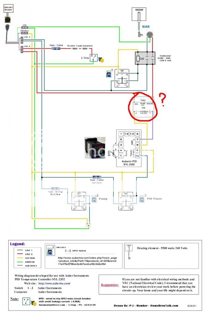
As I am creating my shopping list for this control panel, the image above shows one piece of the control panel that I am not sure what it is. Can someone tell me what that is? I think it may be the SSR but am not sure. The only change to the diagram is the addition of a timer.
Also, can you look over my shopping list and see if there is anything major that I am missing here?
CONTROL PANEL INNER WORKINGS:
*All if these are from Auber Instruments and have the model number)
1 PID (SYL-2352)
3 Selector Switch (SW2) (1 for main power, 1 for PID/element, 1 for pump)
E-Stop Switch (SW6) (Optional)
Timer (ASL-51)
40A SSR (MGR-1D4840)
Heat Sink (40A SSR) (HS40)
Contactor (2 pole 30A 120VCoil) (CN-PBC302-120V)
2" RTD Sensor (PT100-L50M14)
Female Plug for Element
Female Plug for Pump
Various fuses / resisters
Input Power Cord
On top of this, I will (obviously) need a heating element, control panel enclosure, and a GFCI of some sort. There is a 50A spa panel at Home Depot for a fair price that I was looking at.
Is there anything blatantly missing or wrong with all of this? My friend is the electrician, and I know very little. Any help would be greatly appreciated")
I have been talking with a friend, who is an electrician, and we are going to work together to get my brew setup electric. I decided I want a single 5500W element controlled by a PID on a control panel. I am using P-J's diagram, shown here:
As I am creating my shopping list for this control panel, the image above shows one piece of the control panel that I am not sure what it is. Can someone tell me what that is? I think it may be the SSR but am not sure. The only change to the diagram is the addition of a timer.
Also, can you look over my shopping list and see if there is anything major that I am missing here?
CONTROL PANEL INNER WORKINGS:
*All if these are from Auber Instruments and have the model number)
1 PID (SYL-2352)
3 Selector Switch (SW2) (1 for main power, 1 for PID/element, 1 for pump)
E-Stop Switch (SW6) (Optional)
Timer (ASL-51)
40A SSR (MGR-1D4840)
Heat Sink (40A SSR) (HS40)
Contactor (2 pole 30A 120VCoil) (CN-PBC302-120V)
2" RTD Sensor (PT100-L50M14)
Female Plug for Element
Female Plug for Pump
Various fuses / resisters
Input Power Cord
On top of this, I will (obviously) need a heating element, control panel enclosure, and a GFCI of some sort. There is a 50A spa panel at Home Depot for a fair price that I was looking at.
Is there anything blatantly missing or wrong with all of this? My friend is the electrician, and I know very little. Any help would be greatly appreciated

