• Please visit and share your knowledge at our sister communities:
  • If you have not, please join our official Homebrewing Facebook Group!

    Homebrewing Facebook Group

NEW StrangeBrew Elsinore Thread

Homebrew Talk

Help Support Homebrew Talk:

This site may earn a commission from merchant affiliate links, including eBay, Amazon, and others.
I assume I can use the same 40a SSRs used in Kal type builds to run the elements?
Yes, any standard SSR that accepts a 5V switching signal.

What would I use to trigger the pumps on and off? Is there a relay or contactor that works best?

You can use SSRs, or relays, either work. There's no automatic trigger, just buttons on the WebUI.

How do I connect the wires to the GPIO connections on the Pi? Do you use an add on board for this? Is there a connector that I can solder to the wire?

This is up to you, you can crimp ends to control wires and plug them in, or you can but things like prototyping capes, or use jumper cables, etc...

Does any one have an example wiring diagram for a build?

The RaspberryPi documentation shows the way I had it wired up: http://dougedey.github.io/2014/03/22/RaspberryPi-Setup/

The three SSRs show the two ways you can wire a element, two SSRs (one per wire) or one SSR (one for on of the input lines, the other is always hot, a bit less safe).
 
I'll use my control panel for fermentation control and serving most of the time, and load a different configuration file and switch over to element and pump control while brewing... perfect & economical.

I'm exploring hiding devices from the WebUI so you may not even need to bother changing the config file, just hide the devices you're not going to use :)
 
Yes, any standard SSR that accepts a 5V switching signal.


You can use SSRs, or relays, either work. There's no automatic trigger, just buttons on the WebUI.


This is up to you, you can crimp ends to control wires and plug them in, or you can but things like prototyping capes, or use jumper cables, etc...


The RaspberryPi documentation shows the way I had it wired up: http://dougedey.github.io/2014/03/22/RaspberryPi-Setup/


The three SSRs show the two ways you can wire a element, two SSRs (one per wire) or one SSR (one for on of the input lines, the other is always hot, a bit less safe).


Thanks for the quick reply. Looking forward to getting this set up! You mentioned crimping ends to the control wire to connect to the Pi. Do you a link to a crimp on end that would work? Sorry I am a bit new to working with these boards.

Thanks!


Sent from my iPhone using Home Brew
 
I'm exploring hiding devices from the WebUI so you may not even need to bother changing the config file, just hide the devices you're not going to use :)

Interesting... I haven't wired any extra ports for temp sensors (probably my largest oversight in my panel build), so I can only have three plugged in now. I think this would give me motivation roll up my sleeves and change that however.

It's not possible for me to fit in any extra relays though - so, you're saying there potentially would be a way of linking a single GPIO to two sensors/PIDs in a single configuration file, with having only one of those PIDs in command at a time.
 
I haven't added this in yet, I've been thinking of it though, at the moment you can just daisy chain the SSRs/relays from the same GPIO.

I meant independently - i.e. a single temp probe that links to one SSR for cooling and one for heating in hysteria and displays as a single device in the UI. A simpler implementation would be the ability to set up two PIDs from the same temp sensor. And of course, the current ability to have two PIDs - one set up for heating, and one for cooling the same kegerator/fermentation chamber is perfectly workable. Especially seeing as you could put two sensors on the end of a single cable (I think this works, been awhile since I thought about the wiring), and the sensors are so cheap.

Not done any changes to the data logging yet, I'm going to be adding in a way to reset the data and to add on data points, and to extract data output to files. I've not looking into Dropbox, since it's not really removing data from the folder.
I'm going to add a custom data logger directory, so you could mount a external drive, or use a network mount, or point it at a dropbox sync folder which should be enough I think.

Data management is something I need to improve so you can chose to delete older logs or view them.

Right on - in the meantime is it possible to reduce the sampling rate for fermentation control situations, or perhaps turn off logging completely in the case of a kegerator? Are current logs stored in memory or on disk? Just thinking out loud here not making feature requests :ban:
 
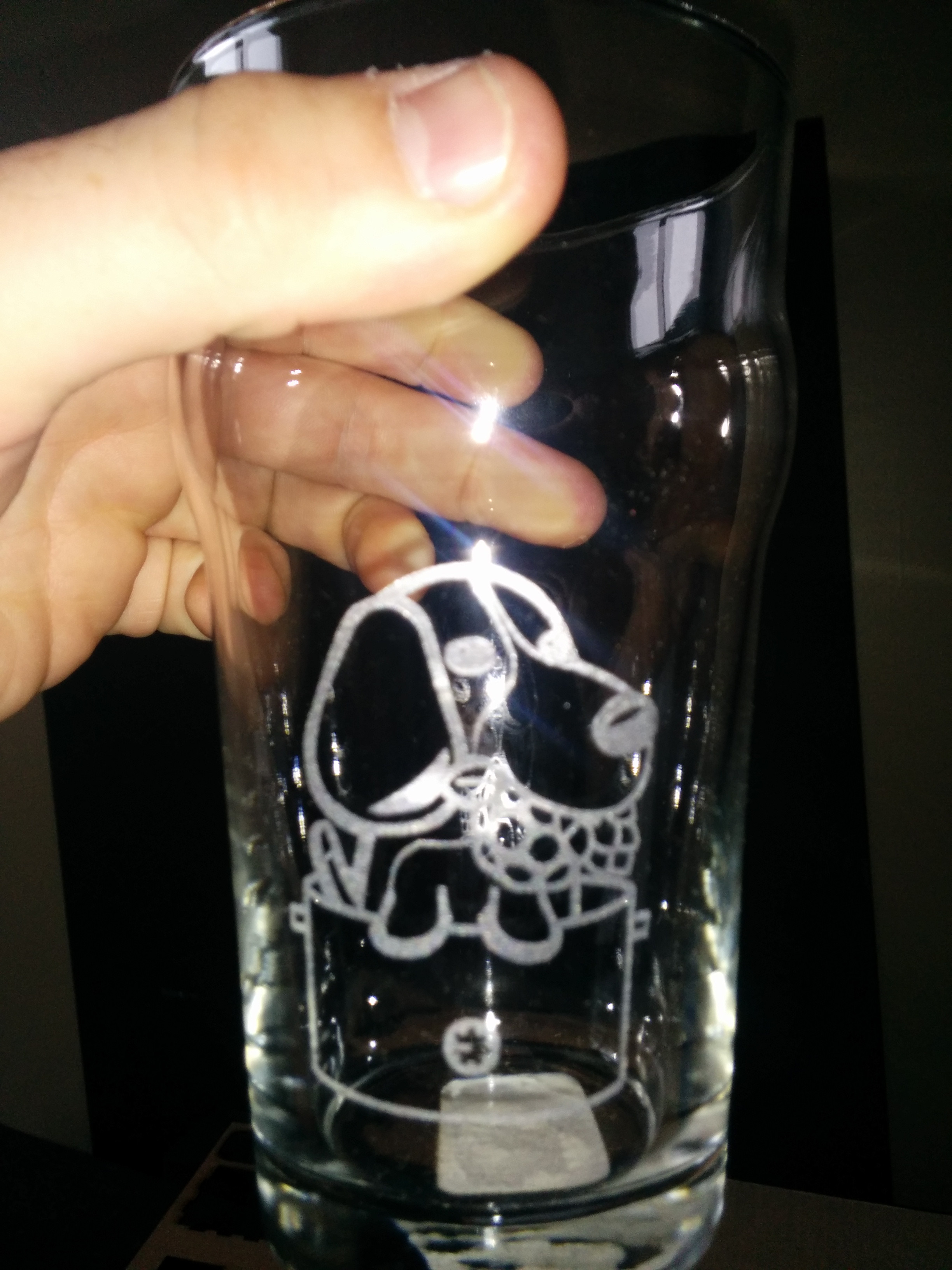
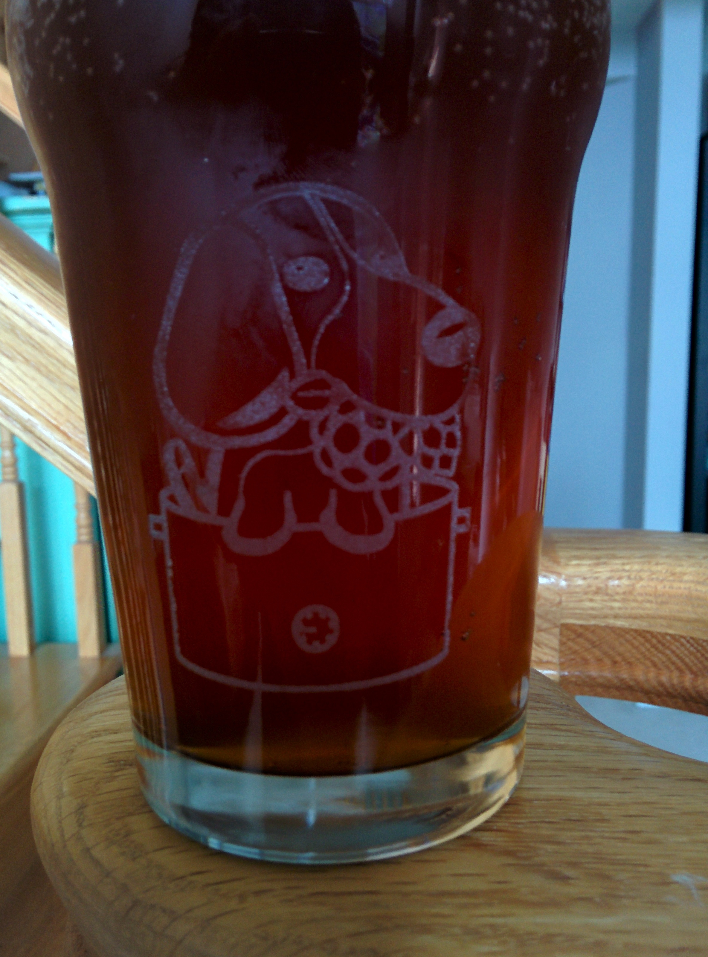
So I finally got myself since glasses engraved, I've spoken to some people and I'll be sending them out to those who have provided a lot of help (and that are in north America, because I don't trust then not to smash getting to Europe, sorry)


dx5x5Na.jpg


v7j6KWV.jpg
 
Interesting... I haven't wired any extra ports for temp sensors (probably my largest oversight in my panel build), so I can only have three plugged in now. I think this would give me motivation roll up my sleeves and change that however.

It's not possible for me to fit in any extra relays though - so, you're saying there potentially would be a way of linking a single GPIO to two sensors/PIDs in a single configuration file, with having only one of those PIDs in command at a time.

You can make a breakout box for extra probes, you can daisy chain remember :)
 
I meant independently - i.e. a single temp probe that links to one SSR for cooling and one for heating in hysteria and displays as a single device in the UI. A simpler implementation would be the ability to set up two PIDs from the same temp sensor. And of course, the current ability to have two PIDs - one set up for heating, and one for cooling the same kegerator/fermentation chamber is perfectly workable. Especially seeing as you could put two sensors on the end of a single cable (I think this works, been awhile since I thought about the wiring), and the sensors are so cheap.

Oh, that's in there, double clicking the title (to edit the device) gives you the ability to add a cooling GPIO (I think there's some logic missing, I'll finish confirming tonight).


Right on - in the meantime is it possible to reduce the sampling rate for fermentation control situations, or perhaps turn off logging completely in the case of a kegerator? Are current logs stored in memory or on disk? Just thinking out loud here not making feature requests :ban:

No, I'll add that now. Give me an hour or two :)
 
Thanks for the quick reply. Looking forward to getting this set up! You mentioned crimping ends to the control wire to connect to the Pi. Do you a link to a crimp on end that would work? Sorry I am a bit new to working with these boards.

Thanks!


Sent from my iPhone using Home Brew

Double check what I'm saying, but something like this: http://www.adafruit.com/products/349

Though you'll need to use crimp connections that fit it.

The other way is to get prototyping male-male or female-female cables and just cut off the end you don't need. Then you can solder away.
 
Updates: the status recorder (logs) can be disabled using
Code:
-r false
And the recorder output directory can be set using
Code:
-s <directory>
 
And the manual duty mode had some issues, all fixed (I think). There's now three different duty modes.
 
Last edited by a moderator:
Interesting... I haven't wired any extra ports for temp sensors (probably my largest oversight in my panel build), so I can only have three plugged in now. I think this would give me motivation roll up my sleeves and change that however.

It's not possible for me to fit in any extra relays though - so, you're saying there potentially would be a way of linking a single GPIO to two sensors/PIDs in a single configuration file, with having only one of those PIDs in command at a time.


Just for you jangevaa, you can now hide devices/temps from the WebUI, even if they're not setup. When you're in edit mode you'll see all the devices, and when you click the title of a device to modify it, there'll be an extra button, "Hide" or "Show" to change the state. Click it, and when you've locked the UI the elements will be hidden.

In theory, you can run two separate elsinore instances on the same device, just don't cross the GPIO outputs, or things'll get weird.
 
For the pumps I would just use regular mechanical relays. SSRs are great for loads that need to be switched repeatedly but they get HOT and need to have heat sinks and thermal management planning. Standard mechanical relays do not have that limitation and are perfect for things like pumps or valves where you won't be using PWM/PID. You can use SSRs for pumps, but make sure you account for the heat. There probably won't be nearly as much heat with a 2A pump as there is for a 23A element, but it won't be none.

-Josh
 
The SainSmart 4-channel relay module on Amazon should do well for you. <$10 and leaves you some room for future expansion.
 
That's the one, they must be monitoring this thread because it was just over $9 yesterday. For its current price, another $1.70 gets you the 8-channel board.
 
A quick(ish, it only took me one movie) present to y'all before I go on Vacation for a bit tomorrow.

You can now edit the status recorder (i.e. log recorder) settings from the Web UI.

Hit "Edit" and you'll have the ability to set whether the recorder is enabled or not, and the threshold values, and the minimum time between samplings (in ms).

There's some GUI improvements as well, and some more to come to tidy it up. But I'm away for just over a week and can't do any more testing.

Oh, I've also fixed a couple of migration bugs over the last couple of commits (mainly from when I enabled the cooling control in the Web UI).
 
the only way i could get that relay to work was to build this thing...

http://www.raspberrypi.org/forums/viewtopic.php?t=36225

Ahhhh, this is why people want to use the inverted outputs mode on Elsinore!

The issue would be that using the inverted outputs option inverts ALL the outputs.

I'll add some changes in so you can select an inverted output for an individual pinout (I want to remove as many options as possible so everything can be done from the web interface)
 
Doug-
I have been following your threads for quite a while as I built my three keg super strut system over the last 15 months. I hacked Android onto an HP TouchPad and installed the server on an Rpi and the app on the Touchpad. I have also been building a TeensyPi and a TeensyNet on Jim Mayhugh's thread. Is there a way to Frankenstein-merge your software to that hardware? Just a thought, I am only good at following directions most of the time. Thanks.

The teensypi looks like it already does the basics of what you need for temperature control.

But if you want Elsinore, all you need to make sure is that the /sys/devices/ has one wire on it.

Or you could just try to start Elsinore and see if it works :), I can't give direct support though.

As for android, the Elsinore App isn't supported anymore since Elsinore now has a mature web interface.
 
Thanks for the overview. I now understand the differences. Your work is great... I am glad you continued to improve it for us.
 
Ahhhh, this is why people want to use the inverted outputs mode on Elsinore!

The issue would be that using the inverted outputs option inverts ALL the outputs.

I'll add some changes in so you can select an inverted output for an individual pinout (I want to remove as many options as possible so everything can be done from the web interface)

inverted on selected pins would be awesome. I love this program... you are doing a GREAT JOB.

would love to see timers count down not up.. hehe

how would i go about requesting different features?

thanks again for all your hard work!
 
inverted on selected pins would be awesome. I love this program... you are doing a GREAT JOB.

would love to see timers count down not up.. hehe

how would i go about requesting different features?

thanks again for all your hard work!

If you've got a feature request the best way is to raise a bug on github for it.

The timer count down is something that's taking a lot of thought since I need to identify how to get it to work on the UI, since a new pop up library has come out which is nicer to use, I may revisit it. The other issue (which is still there with the timers) is how to mark the actual start/stop time, originally I did it with a timestamp on the Web UI being sent to the server but there could be a huge difference if you're not using NTP, this is why there's sometimes a couple of seconds between pressing start and the timer starting.
 
Doug - great work on this! I'm very impressed by your work on Strangebrew Elsinore. I'm just wondering how folks handle multiple heater elements on a single controller, especially if power is limited to say 30A. On a typical rig, you might have an HLT and boil kettle with elements, and perhaps a RIMS tube to maintain mash temps. Would it be possible to have the software control output to the RIMS and HLT elements such that the load would never exceed 30A? During heating of the HLT, the MLT element would be off. But, to maintain temp of the HLT once the temp was reached, the element would not need to be on at 100%. During the off time, the MLT element could be on to maintain the mash temp. Once the mash was complete, the RIMS tube could increase to mashout/sparge temp, and then maintain sparge temp while activating the boil kettle element to bring it to a boil. In the best case scenario, we'd all have 60A 240 lines run to our brew stands, but this is rarely the case. Seems like it wouldn't be all that difficult to incorporate some prioritization code to intelligently split the current between heating elements.
 
I'm interested in this too but I'm also in the process of running a 60a circuit. :) I plan on using 4 elements though (2ea in hlt and bk) and then using a hardware pcb I'm still working on to guarantee only two could be fired simultaneously with priority of having one on in each if both are heating and then two on in one only if the other vessel isn't heating or is in a dwell period of the PID functions. It'd be easier in software, but I wanted a foolproof design in case a software glitch enabled more than two (or in your case more than 1) for whatever reason.

It gets tricky also because most ssrs are zero-crossing meaning they only switch states when the phase of the AC power crosses 0. This means that even if the controller only had one of your two outputs high at a time, you'd have to make sure one didn't activate within 1/120 of a second to ensure the other ssr had crossed zero and switched off.

Edit: forget that second paragraph. As I lay here thinking about it, as long as all of your ssrs are zero-crossing it shouldn't matter since the other wouldn't change state until crossing zero either. If you're mixing and matching ssr types, you would still have to take that into account. ORRR...Just assume that the sub-second nature of the times they may overlap would not be enough to trip the 30a breaker or heat up your wires substantially.

-Josh
 

Latest posts

Back
Top