• Please visit and share your knowledge at our sister communities:
  • If you have not, please join our official Homebrewing Facebook Group!

    Homebrewing Facebook Group

Nessie's Dope Ass Brew-Haus V2.0

Homebrew Talk

Help Support Homebrew Talk:

This site may earn a commission from merchant affiliate links, including eBay, Amazon, and others.

Nessie

Active Member
Joined
Jul 3, 2016
Messages
42
Reaction score
3
Location
Newport News
Good day!

I'm making this thread to document my build process, hopefully it's in the right place.

Bit of background:
I have about two years of brewing experience, all extract. Got the itch to go all-grain from the moment I first read about it and have been working on the transition for the past year. I work in a technical field, so I'm familiar with drudging through manuals and spending hours researching before pulling any triggers. That being said, I am not very familiar with residential/civilian electrical work so bare with me.

The setup so far:
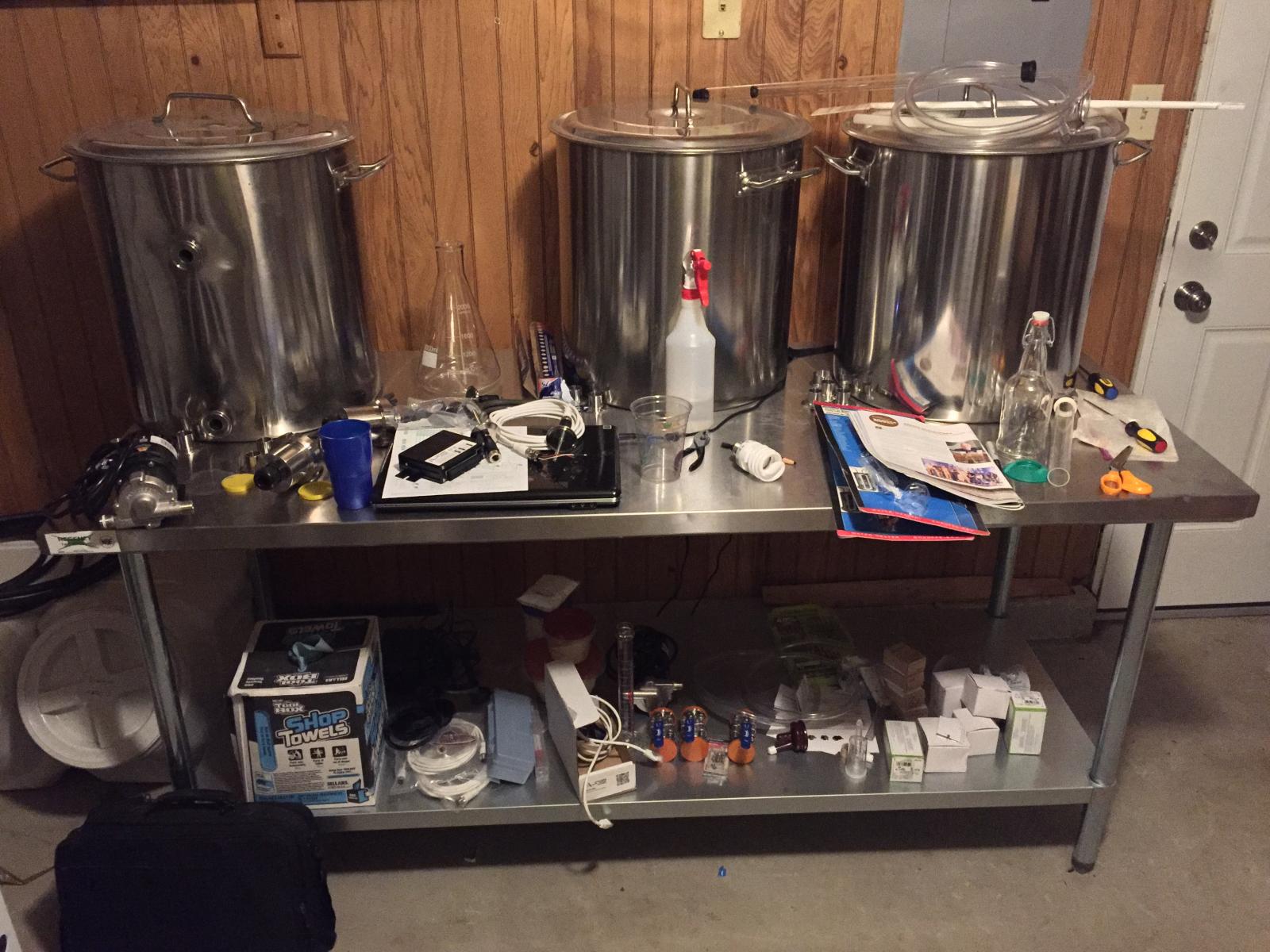
The vision is an electric HERMS brewery powered by a BCS 460. I have in my custody two 5500 watt ULWD heating elements, 3 80 QT kettles, 2 110vac Chugger pumps, a BCS 460, SSR's, temperature probes, various tri-clover fittings, ball valves, Hx's etc..

The kettles and fittings are off to the welder, so my focus is shifted to the control panel. I've been thumbing my way through several schematics and have a couple of ideas that I'd like to implement, though I am not sure if they are feasible and haven't been able to find a post that addresses the issue. So here I am, ready to air out my dirty.. dirty laundry.

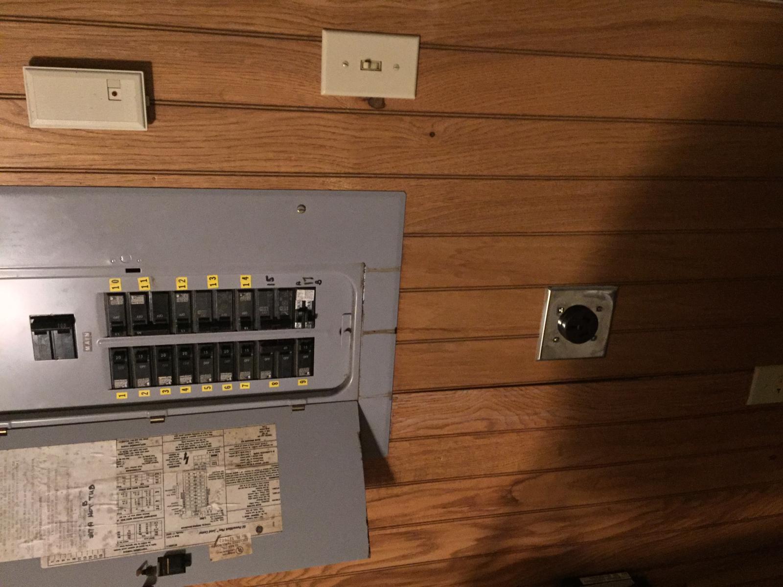
I have a 240vac outlet with a 50 Amp breaker ready to feed the panel, however it is split phase with a ground. So three wires, H-H-G, with the out of phase wires acting as the 'neutral' every half cycle (at least that's how I understand it).

What I'd like to do is ...

1) Have the 240vac feed a bus bar inside the panel and then transform it down to a 120vac bus bar(if that's possible/feasible) to supply power for the pumps. In my head this is the cleanest option, if you could retain the split phase properties during the transformation.

2) The other school of thought is that I could feed the 120vac bus bar with 1 leg of the 240vac bus, though essentially eliminating the neutral (and exposing gaps in my knowledge *gulp*).

3) Have multiple power sources, one 240vac and one 120vac from two separate outlets (not preferred) to feed two separate busses. Not clean, but it would work.

I have a bunch of pictures and some schematics that I will post in a bit.

Any help is appreciated!
 
Looking forward to seeing your photos etc.

BTW Your main fuse panel in your house is esentially a "bus bar" that uses either leg of the 240v feed for the 120v outlets in your house. Not sure what you mean by eliminating the neutral?
 
With Hot-Hot-Ground per your description, you have no Neutral, hence you cannot power 120V devices. Get 240V pumps and you are good to go.

That's the conclusion that I came too as well, at least with the method of using one leg. Though I still think that it might be possible to use a step down transformer to create a split phase 120vac. I don't know if anything out there exists, but this is the route that I'm looking into right now.

Unfortunately I already have my 110vac pumps, so I'm going to be pretty stubborn about finding a solution that doesn't cost me two more pumps :)

Thanks for the replies, I'm still putting together decent looking schematics in Microsoft Photoshoop ( aka MS Paint).
You can always go with 24v DC pumps like the TD5 or smaller p38i (powed by a dc powersupply running off the 240v like I do)... I use three p38i's permanent plumed into my system for almost 4 years now.. they work well and pump about 3 gallons per minute which is a lot considering how tiny they are.. I also use pwm speed controller to control the speed instead of ball valves...
Just another option to consider... Bobby sells the stainless TD5 version and the p38i version sells for about $18 shipped.
 
Thanks for the input augiedoggy, I hadn't considered DC pumps. If all else fails that could be a cheaper alternative.
 
Looking forward to seeing your photos etc.

BTW Your main fuse panel in your house is esentially a "bus bar" that uses either leg of the 240v feed for the 120v outlets in your house. Not sure what you mean by eliminating the neutral?

Thanks for the reply! The 240v line coming into my panel only has 3 wires, no dedicated neutral wire. So if I take one leg of the 240v line to try to make a 120v bus inside the panel, I only have one wire feeding the bus with no access to the neutral bus inside the main panel.
 
How many wires are actually in the junction box of your 240V plug? If you have 4 wires to your junction box, you could just change the receptacle to a 4 wire one.

Brew on :mug:
 
How many wires are actually in the junction box of your 240V plug? If you have 4 wires to your junction box, you could just change the receptacle to a 4 wire one.

Brew on :mug:

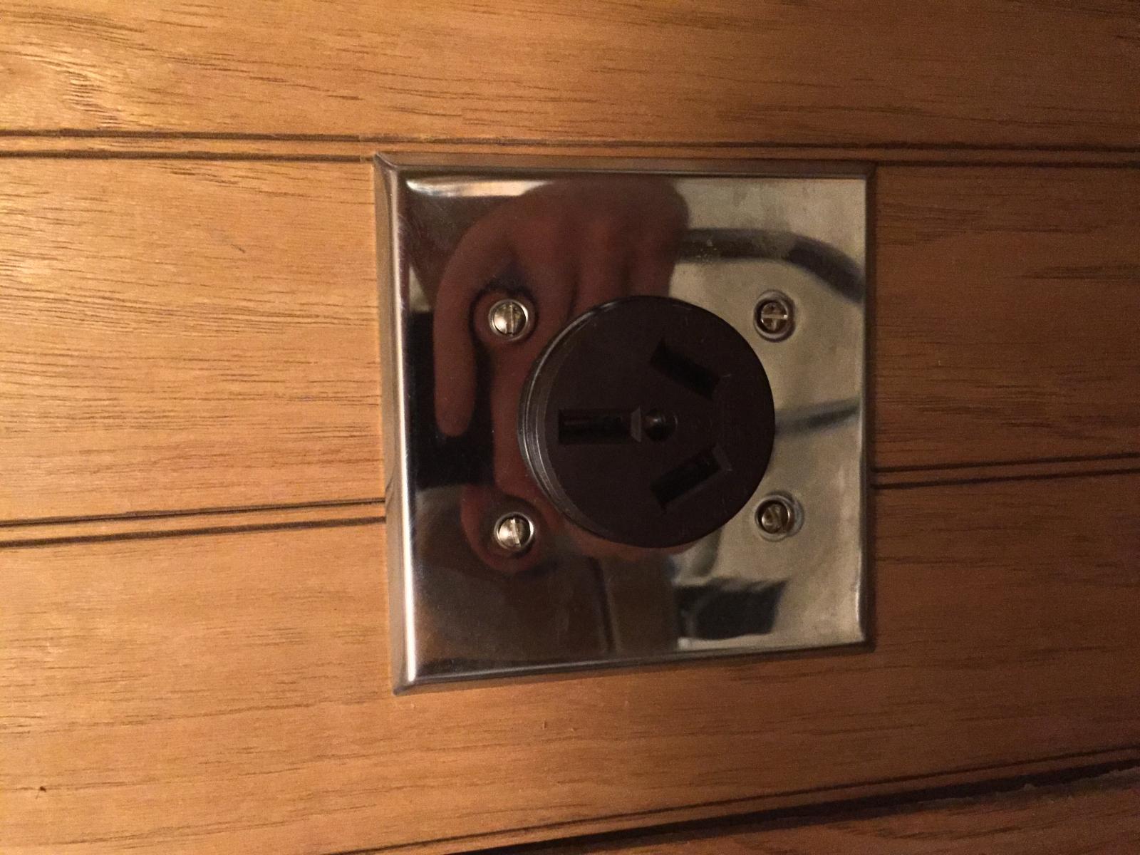
Haha, good question! I popped it open, it's three wires. That would have been a fun conversation with the electrician ;D
 
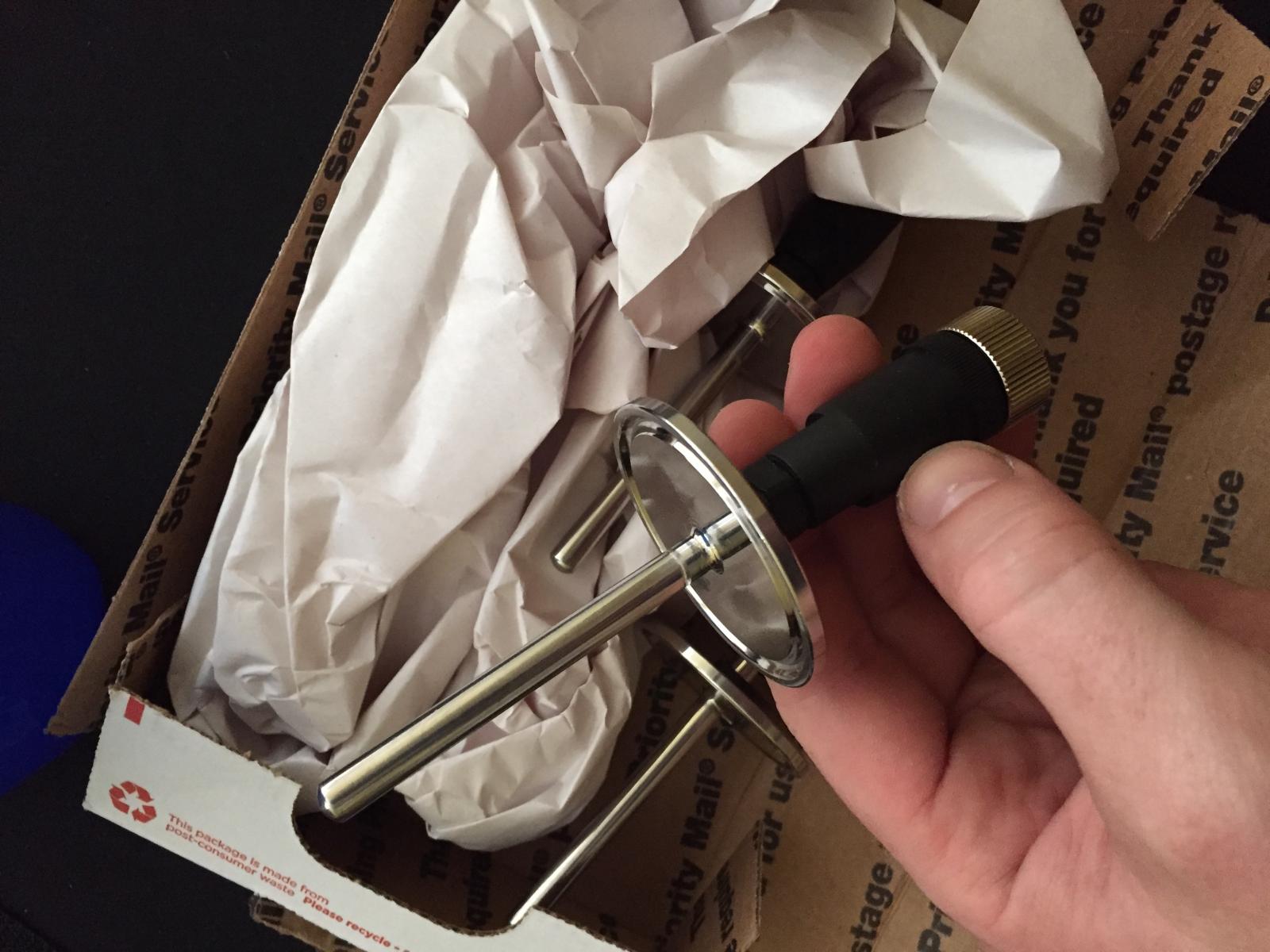
Here's some photos of the build so far, not including schematics. I like to draw my schematics by hand so I'm still working on the final draft before I post it :D

It's mostly just part accumulation right now.

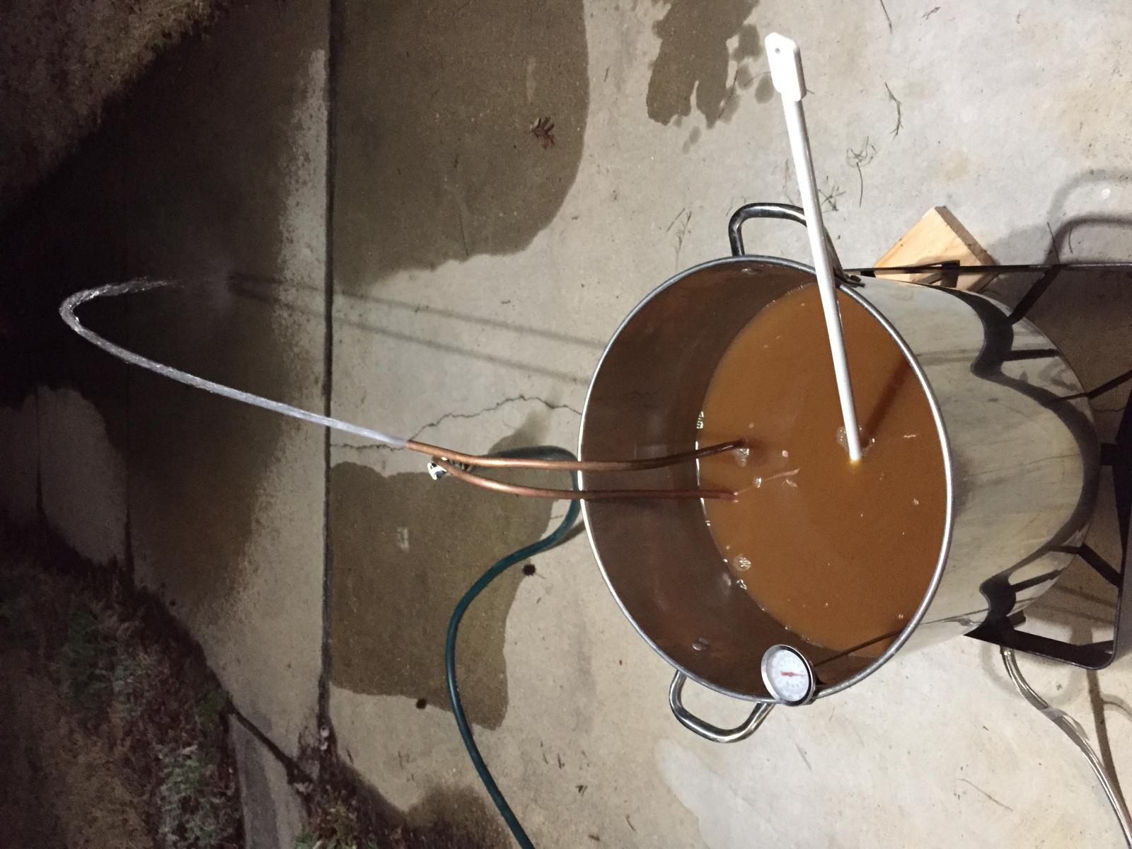
Old Dog.jpg


CB's and Outlet.jpg


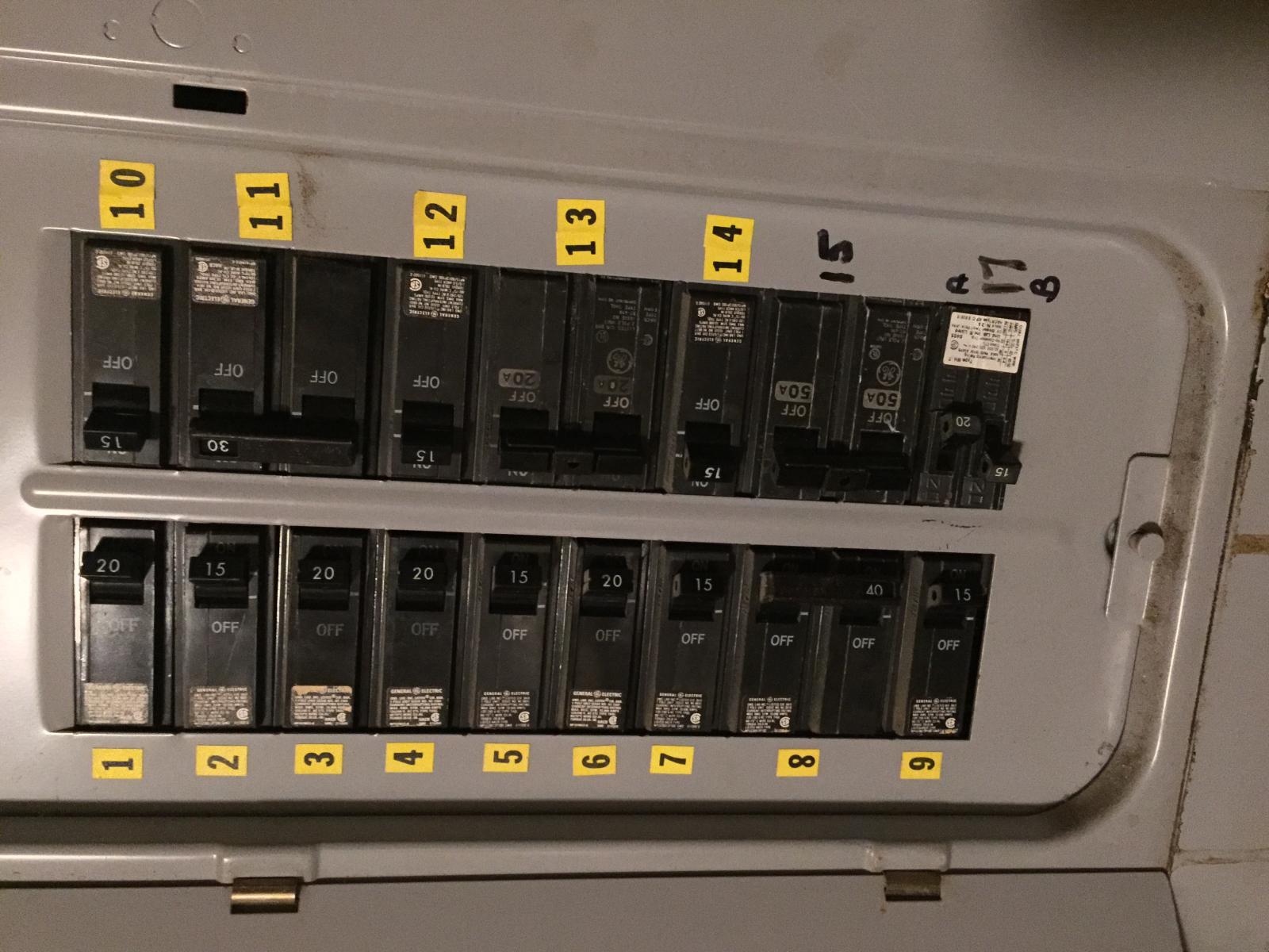
CB Box.jpg


220vac 3 wire.jpg


Hot Mess.jpg


Temperature Probe with disconnect.jpg
 
33943118191_9c36d1c4d3_k.jpg
Here's the schematic for the mechanical side of things. Pictured is a bypass on the HLT, which I have deemed unnecessary and am no longer including.

Control panel soon to come!

Cheers!
 
Run another cable 2 hots 1 neutral and 1 ground. 4 wire cable. And poof your done. 5 feet of cable cheap. One new plug cheap. Hell there is even panle board so you dont even have to patch and paint drywall. Cheap cheap cheap.
 
Run another cable 2 hots 1 neutral and 1 ground. 4 wire cable. And poof your done. 5 feet of cable cheap. One new plug cheap. Hell there is even panle board so you dont even have to patch and paint drywall. Cheap cheap cheap.

If the house is designed to have 3 wire 220v, is it likely that a neutral even exists? I haven't opened the breaker box yet, but the whole point of 3 wire is to conserve material by not having to run the 4th wire. I'll crack it open later and check it out, but it would still be cheaper at this point to run with a 40 dollar transformer than to buy a new plug and cables. I rent the house so I'm not exactly authorized nor inclined to perform any electrical work that could make the place out of code.
 
Unless you are saying that every plug in the whole house is 220V (it isn't), you have a neutral. I think you need to learn about split phase home wiring before building an electric panel. I know there is a diagram on here somewhere, but "split" phase means two lines, 180 degrees out of phase. Across the two is 220V. From one to neutral is 110V, from the other to neutral is 110V.

I am sure if you asked the home owner if its OK for you to upgrade the receptacle, they should have no concern, as you are tecnhically making it "better".

Oh, we should mention the breaker needs be GFCI.
 
I think you need to learn about split phase home wiring before building an electric panel.
^^^^^^ THIS ^^^^^^

Both Lowes and Home Depot have a short book on basic electrical theory, wiring, etc. It's a good reference for someone just starting out. Once you have the basics, it all makes much more sense.
 
We want you Dope Ass, not Dead Ass!

Haha, thanks I appreciate the concern. I understand the concept of split phase, I work with 3 phase AC at much higher voltages, though the electrical circuits I work on are nothing like residential wiring so there is a bit of a learning curve.

Rest assured I won't perform any maintenance that I am not 100% confident in my safety.

I didn't mean to say that all of my outlets are 240v, if that were the case I wouldn't have paid an electrician $200 to wire up a 240v receptacle for me! Unfortunately I did not understand I was getting shafted a wee bit when they installed the 3 wire outlet, though I did not specify that the component it would be powering would require 120v and 240v. Since they didn't know this, they gladly put in a 3 wire to meet the bare minimum requirements and went on their way.

The more I think about it, the more I am leaning towards running a neutral wire to the outlet and installing a 4 wire plug. No room for jury rigging in this bad, bad boy...

Thanks for the input all, this forum is a good sounding board for my thoughts. :taco:
 
Last edited:
18199340_10209050842566580_5069601568367959975_n.jpg

These went together very satisfyingly..

4 SSR's on heat sinks, and some sticky icky thermal compound, sliding all up on some DIN rail.

Think I'll need a heat sink on the panel?
 
View attachment 399256

These went together very satisfyingly..

4 SSR's on heat sinks, and some sticky icky thermal compound, sliding all up on some DIN rail.

Think I'll need a heat sink on the panel?

If you are going to use these din rail heatsinks then no you don't need a heat sink mounted to the outside of the panel. What you will probably need are a couple of holes and a computer fan to circulate air through the panel to keep those din rail heatsinks cool.

When people use a heatsink mounted to the outside of the panel they mount the SSRs directly to that heatsink.

Edit: you have asked a few questions in this thread that indicate that you do not have a solid understanding of house electrical wiring. I would take others suggestions a little more seriously about educating yourself more before you jump in too far on this build.
 
If you are going to use these din rail heatsinks then no you don't need a heat sink mounted to the outside of the panel. What you will probably need are a couple of holes and a computer fan to circulate air through the panel to keep those din rail heatsinks cool.

When people use a heatsink mounted to the outside of the panel they mount the SSRs directly to that heatsink.

That's what I figured. Thanks.

Edit: you have asked a few questions in this thread that indicate that you do not have a solid understanding of house electrical wiring. I would take others suggestions a little more seriously about educating yourself more before you jump in too far on this build.

All suggestions have and will be taken into consideration. #relax
 
Back
Top