Need some feedback on wiring

Homebrew Talk - Beer, Wine, Mead, & Cider Brewing Discussion Forum

Help Support Homebrew Talk - Beer, Wine, Mead, & Cider Brewing Discussion Forum:

This site may earn a commission from merchant affiliate links, including eBay, Amazon, and others.

kokonutz

Well-Known Member
Joined
May 5, 2020
Messages
73
Reaction score
9
Location
Campbell River
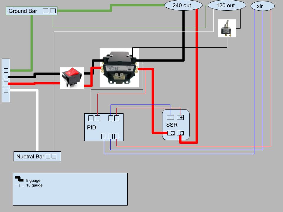
Attached is my first go at a wiring scheme for a control panel, but I have some questions. Of course, waiving any liability to any participants, can I get some feedback regarding the attached?

I'm looking to do a 15-20 gallon 2 vessel, one pump system. I would also like to have the pump power run through my CP. My element will very likely be 4500 watts...it's the only all stainless I could find (open to other suggestions there....); this puts the unit into the 30amp arena which is fine, but seems to enter a new layer of concerns regarding both safety and protection of the equipment.
  • Do I need an in unit circuit breaker as well as the one from our house main?
  • Do I need fuses around the switches?
  • Given the element alone could draw close to 20 amps , does the main power switch need to be rated above that? I only choose this switch because it rated up to 30 amps
The list of components
Contactor - Packard 230b
Pump switch
Main Switch - 4 pin rocker

Thanks all
 

Attachments

  • CPschema.jpg
    CPschema.jpg
    55.6 KB · Views: 53
You are using the switch and contactor incorrectly. The switch should control the 120V hot wire to the contactor coil, not be in series with the high current wires. Check out the schematic below to see how contactors are wired.

The high current path wiring only needs to be 10AWG for 30A. Using heavier wire than necessary will only make your build more difficult. The low current wiring can be 16AWG to power the pump, and 22 - 18AWG for powering the contactor coil and PID.

You don't need a breaker internal to the control panel if the power feed has a 30A breaker in the main service panel. The 30A breaker should be a GFCI breaker, as it's the GFCI that keeps you from getting fried. A regular fuse/breaker only protects the wires from overheating.

You should also add fuses in the control panel where the wire size gets reduced. A 10A fuse to protect the 16AWG wire, and a 1 - 2A fuse to protect 22 - 18AWG wire. Again, look at the diagram below to see how to add fusing.

DSPR300 2-Pump 1-Element 240V rev-2.PNG


Brew on :mug:
 
Oh thank you...so by that schematic, it appears there is a main switch, and then switches to each unit (pump and element). And in the case of the element, we require another contactor because of the heavy load , where as the 120 can pass directly thru that SW11 switch.
 
Oh thank you...so by that schematic, it appears there is a main switch, and then switches to each unit (pump and element). And in the case of the element, we require another contactor because of the heavy load , where as the 120 can pass directly thru that SW11 switch.
Correct.

You can get by without the main power contactor, and only have an element enable contactor, if you don't want to have the "Safe Start" function. Safe start prevents you from turning on the main power if any of the pump or element enable switches is on. Prevents possible nasty surprises if you didn't reset all the switches before starting up.

It's also possible to eliminate contactors altogether if you have a 30A DPST switch. The following shows a design that does this:

DSPR120 1-Pump Simple.PNG


Brew on :mug:
 
From your schematic, the picture of what looks like a contactor is puzzling, as are the two outputs going to the PID?

If you are using an SSR for the heater, then the SSR and main switch is all that needs o be in series before the heater output.

Under 50 feet, and 10 AWG wire is all you need up to 30 amps (8 awg seems overkill and tough to work with).

A 4500W element would be expected to draw about 19 amps if your service and everything in-line still delivers 240V. At 220V, you are more like 20 to 21 amps. (edit: been working with too many motors lately) So, ya, 30 amp service is the way to go. Given that, why not go with 5500 W heater - faster heating and available from several HB suppliers (Brew-Boss, Spike, maybe Amazon).

Your house breaker will most likely be a 30 amp trip. So that's fine for overload. But anyone or anything will already be dead or in flames before the 30 amp overload trips a breaker. So you ought to consider a GFCI breaker - either in your main panel, or in your controller. For me, the 30A wall outlet is shared by a table saw (inductive) and/or generator, so full-time GFCI on the outlet is undesirable. A two pole 240 V GFCI breaker (you need L1, L2 AND Neutral to allow for both 240 V and 120 V peripherals) will cost you about $100 (4 good four-packs of beer). IMO, it's worth the money for safety and just the peace of mind - plus your controller will have protection that most commercial units costing $500 to $1200 don't even have.

And as doug293cz pointed out on another thread, you want a Class A GFCI, with 6 mA trip - NOT 30 mA trip.

-Greg
 
Last edited:
I like that safe start set up. It took me a minute to figure it out, but that's a great idea.
 
I like that safe start set up. It took me a minute to figure it out, but that's a great idea.
Thanks. I figured it out myself. I won't say I invented it, as it might have been done before, but I haven't seen it. The Electric Brewery uses an additional relay to implement their safe start, instead of just making the main power contactor self latching.

Brew on :mug:
 
...

A 4500W element would be expected to draw about 19 amps if your service and everything in-line still delivers 240V. At 220V, you are more like 20 to 21 amps. So, ya, 30 amp service is the way to go. Given that, why not go with 5500 W heater - faster heating and available from several HB suppliers (Brew-Boss, Spike, maybe Amazon).

...
A heater element is a fixed value resistor, not a fixed power output. The power delivered is determined by the resistance of the element, and the voltage at the element terminals. It only delivers rated power if the applied voltage is actually at the rated voltage. The equation you need is a combination of:
  • V = I * R, and
  • P = I * V, or I = P / V
Which can be combined to give you:
P = V^2 / R, and R = V^2 / P​
So, an element that delivers 4500W when 240V is applied has a resistance of:

R = 240^2 / 4500 = 12.8 ohms​
So, now we can calculate the power delivered for various applied voltages:
@ 230V: P = 230^2 / 12.8 = 4133W​
@ 220V: P = 220^2 / 12.8 = 3781W​
To figure out the current for various powers, use the I = P / V equation:

@240V: I = 4500 / 240 = 18.75A​
@230V: I = 4133 / 230 = 17.97A​
@220V: I = 3781 / 220 = 17.19A​

Brew on :mug:
 
can I ask a quick question on the fuse implementation. I understand that if we ever step down (10awg ->16 awg) we need a fuse. How do we know 1amp vs 10amp?
 
can I ask a quick question on the fuse implementation. I understand that if we ever step down (10awg ->16 awg) we need a fuse. How do we know 1amp vs 10amp?
Wire and fuse sizes are determined by the load current that flows thru the wire. 16AWG wire is good for up to 10A of load current (for other wire current ratings see here.)

A typical Chugger pump draws 1.4 A, so you can run a couple of pumps from a 16AWG feed, and the 16AWG should be protected with a 10A fuse. Motors have a current spike when starting up, so having some headroom on the fuse and wire rating is a good idea. PID's and contactor coils take about 0.05 A @120V, so you can run a bunch of them from a circuit branch fused at 1 A (which is what I typically do.)

Brew on :mug:
 
Back
Top