• Please visit and share your knowledge at our sister communities:
  • If you have not, please join our official Homebrewing Facebook Group!

    Homebrewing Facebook Group

Native ESP8266 BrewPi Firmware - WiFi BrewPi, no Arduino needed!

Homebrew Talk

Help Support Homebrew Talk:

This site may earn a commission from merchant affiliate links, including eBay, Amazon, and others.
I'll eventually distill the forum posts here about the PCBs (complete with bill of materials) into a .md file in the repo as well, but that will come at a later date. Wanted to get the eagle files out there, even if they're not officially documented.
I'd be happy to do that part. I've never done any contributions to a git repository but maybe I can get one of the other nerds here to help. In the meantime I can at least put the text to (virtual) paper.
 
No LCD Support, no buzzer, with screw connectors, and through-hole components.
Purchase Boards

Eagle Files:
  • TBD
Bill of Materials:


LCD Support with DuPont connectors, and surface-mount level converter components.


LCD Support with DuPont connectors, through-hole components, and a SparkFun-based level converter sub-board.


LCD Support with screw connectors, through-hole components, and a SparkFun-based level converter sub-board.
 
If that looks good, I'll work on an .MD file later on today or tomorrow.

Also, will you be uploading the Eagle files for the original? It's possible people may use it if they have no intention of using an LCD.
 
Because soldering 1 mosfet isn't difficult enough [emoji30]

That's why pcbs.io gives you four chances :)

Seriously though, if I ever get a chance to clean up the photos, I built a board with this level shifter design previously, having had absolutely no experience with SMD components. It worked perfectly the first time.

For anyone worried, YouTube soldering videos help immensely, and using SMD components somehow make the board feel that much more "official". This in addition to the cost savings from the smaller board and reduced number of components.
Did/do you reflow it or do you use an iron?
 
Did/do you reflow it or do you use an iron?

I used an iron. The thing I didn't realize is that by pre-placing solder on the pads, when you remelt the solder it will "grab" the component and hold it in place. Then all you need is a pair of tweezers or forceps to hold the component in place.
 
Hrmum ... maybe. :)

I'll get through the other board first and see if I am feeling froggy.

BTW, I dropped the board info in an .MD file in GitHub. Not sure if it notified you. I've updated it once since then too.
 
Hrmum ... maybe. :)

I'll get through the other board first and see if I am feeling froggy.

BTW, I dropped the board info in an .MD file in GitHub. Not sure if it notified you. I've updated it once since then too.

I'm pretty sure I missed a GitHub setting somewhere as I don't get any kind of external notifications (email, etc). That said, I just merged it (with your update).

Thank you!
 
I'm pretty sure I missed a GitHub setting somewhere as I don't get any kind of external notifications (email, etc). That said, I just merged it (with your update).

Thank you!
Somehow I managed to upload it and it shows as text and not an .MD file. Any idea what I did wrong? It was definitely an .MD file when I uploaded.

ETA: I changed the file name, it needs to be merged now. Sorry about that.
 
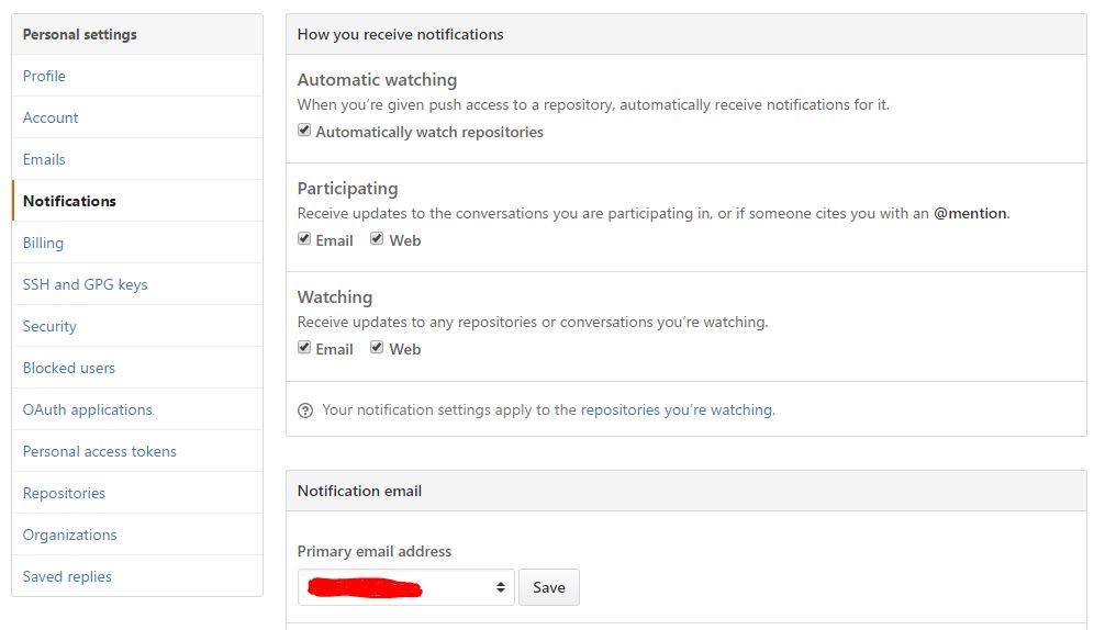
I'm pretty sure I missed a GitHub setting somewhere as I don't get any kind of external notifications (email, etc).
Mine work - here are my settings:

Capture.JPG
 
So here's the question that's plaguing me today. Maybe this is an easy answer, maybe it's something that you've already figured out:

I have an Arduino running now. There's no sense in removing it since it works. Let's say I want to expand to add additional fridges. Will it be possible to support a serial/USB-attached device (the Arduino in this case) as well as multiple WiFi devices?

I guess it would be more cost-effective to replace the Arduino (assuming I had another task for my Arduino) with an ESP8266 even if I intended to use it as a serial-attached device huh? Even then the same question would apply.

Yes. Each device requires a separate installation of BrewPi on the Raspberry Pi itself. You can have one running over serial and as many running over WiFi as you like.

My (target) installation is 1 "native" (Fuscus) and 1-2 ESP8266 on a single Pi Zero, but I'm not quite there yet.
 
Edit: Strike that temp probes aren't updating when i assign them, although the console suggests they are... time to start searching the threads again.

A fresh install of Raspbian Lite, a little bit of faffing i've managed to get an RPI zero and Wemos D1 up and running as brewpi.

Not sure if it's a website problem but the github instructions are linking through the dead pages,but to be honest the videos were enough to get my by.

Cheers Thorax
 
Edit: Strike that temp probes aren't updating when i assign them, although the console suggests they are... time to start searching the threads again

That's odd. Did you try resetting the controller settings back to defaults after doing the initial install? What do you mean that they aren't updating?

Not sure if it's a website problem but the github instructions are linking through the dead pages,but to be honest the videos were enough to get my by.

Hmm. Are you reading the instructions on GitHub? If so, do you mind posting the link as you see it to the page that doesn't work?

It's likely me having screwed up something in the .md file - I'm far from an expert on these things.
 
Hmm. Are you reading the instructions on GitHub? If so, do you mind posting the link as you see it to the page that doesn't work?

It's likely me having screwed up something in the .md file - I'm far from an expert on these things.
I see it, I have some time. I'll fix and do a pull request.
 
That's odd. Did you try resetting the controller settings back to defaults after doing the initial install? What do you mean that they aren't updating?

OK to explain it better... I go into device configuration refresh and my two temp probes appear, i add one to device slot 0 and set up in exactly the same configuration that i have on my other Brewpi.

Device 0, chamber 1, chamber device, chamber temp
Device 1, chamber 1, beer 1, beer temp

i click apply and it puts out this Device config command sent, U:{"i":"0","c":"1","b":"0","f":"5","h":"2","p":"12","a":"28FF66022E040099"}

this is the fridge temp. but the temp doesn't appear in the LCD, but also when i refresh it unassigns itself from the device etc.


Hmm. Are you reading the instructions on GitHub? If so, do you mind posting the link as you see it to the page that doesn't work?

It's likely me having screwed up something in the .md file - I'm far from an expert on these things.

so for me i'm getting a 404 error on all the links under documentation here -> https://github.com/thorrak/brewpi-esp8266
 
Hmm. Are you reading the instructions on GitHub? If so, do you mind posting the link as you see it to the page that doesn't work?

It's likely me having screwed up something in the .md file - I'm far from an expert on these things.
Fixed and pull request submitted.

Look at me learning Github and Markdown!
 
@thorrak advanced settings -> Reset controller to factory defaults has solved the problem.

I can now assign devices and they stay assigned.
 
has anyone had an issues with their Wemos D1 mini just dieing?

As you can see yesterday everything was going well, i turned it off overnight as it's not being used, and this morning there is seemingly no power.

I'm pretty certain i bought it from the aliexpress seller that is linked on the Wemos website? strike that it was here -
 
think my dead Wemos may have died because i initially powered it through a phone charger rather than my computers USB port, apparently some people have reported that doing that can cause the 5v circuit to fry? i have no idea whether that's possible or not or make sense.

powering the D1 through the 5v and G GPIO seems to work fine so i guess i must have broken the micro USB port somehow...
 
Those are tiny and relatively fragile connectors - I'm not surprised it's damaged. I had to perform microscopic surgery on a Kindle Fire where some of the contacts got crossed within the connector. It was amusing I'm sure to my wife seeing me with my glasses + 4x magnifying glasses on my head.

I have all my parts except my boards ... I forget how long pcbs.io took last time but it feels like FOREVER. :)

Reminder to @Thorrak : There's a pull request to fix the Readme.md.
 
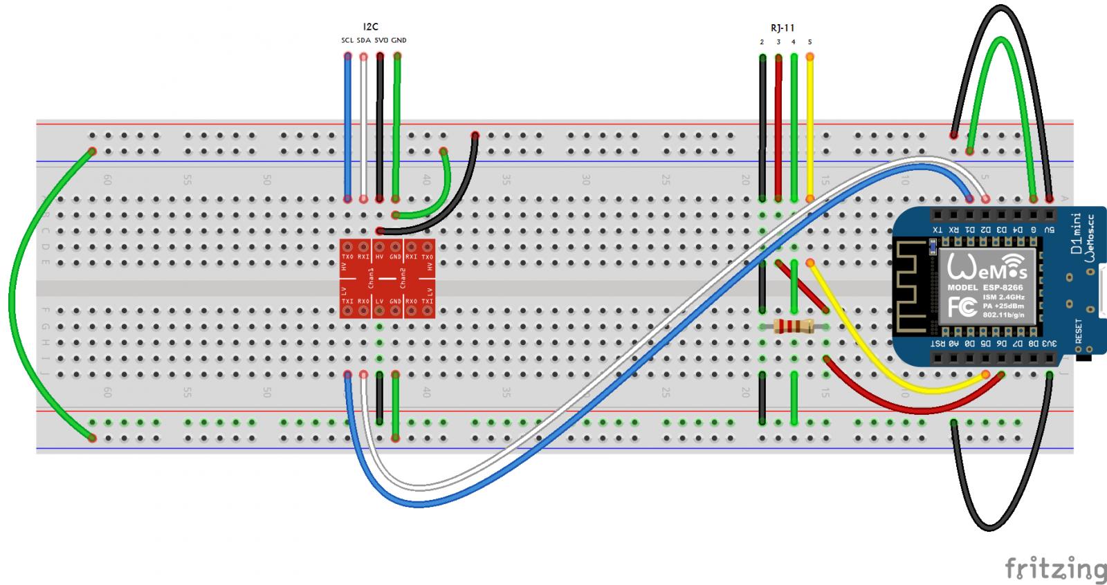
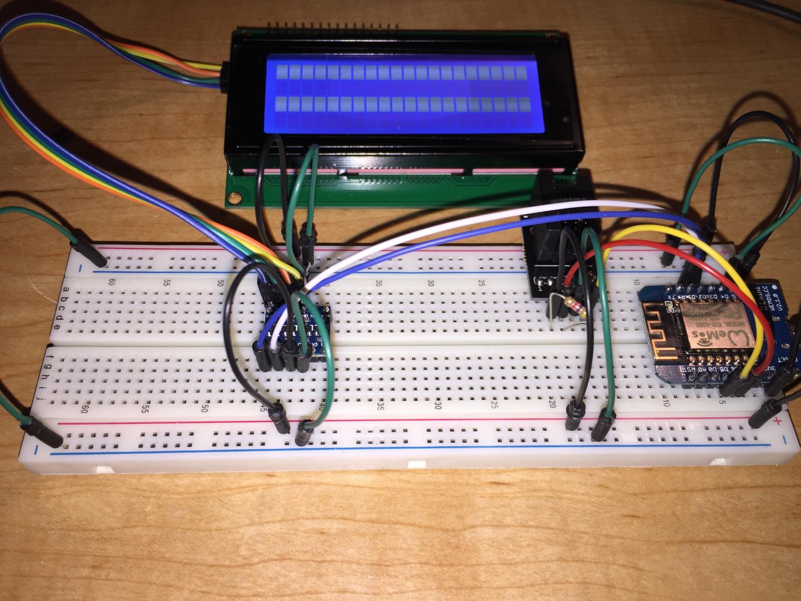
can't see what's going on with the pull up resistor
It's bridging power and data.

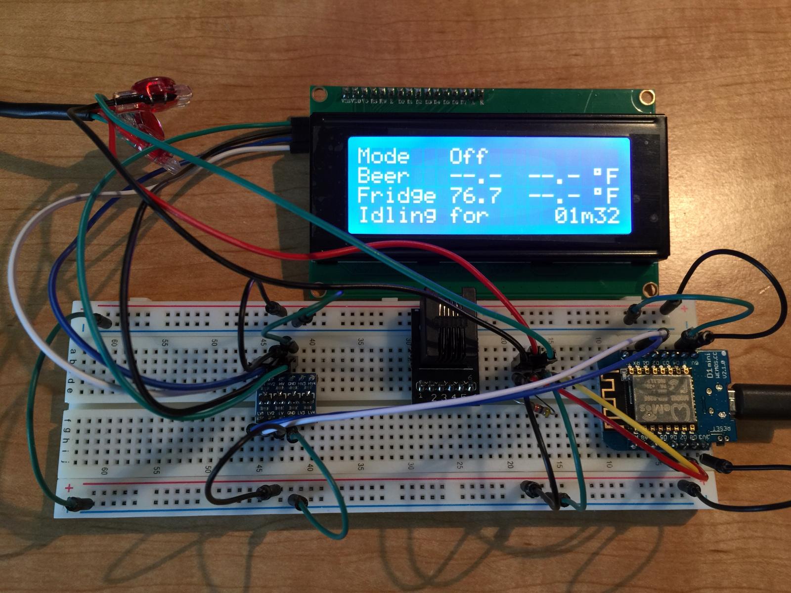
Hmm. Do you happen to know the I2C address of your LCD screen?
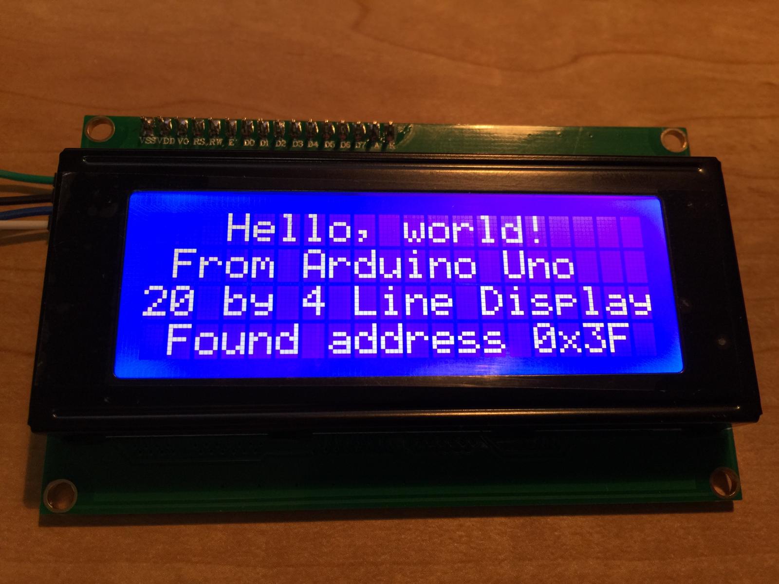
I do (now) ... and it's not 0x27. :rolleyes:

I just found the post where you said you would need to recompile for a different address. Is that not something that could be configured at runtime or is that too much of a PIA?

IMG_5414.jpg
 
I used this code to find the address. Would it be possible to insert this code to allow the program to find and use the display's address on it's own? Seems like it should be able to do that since it would be the only I2C device:

Code:
// I2C Scanner
// Written by Nick Gammon
// Date: 20th April 2011

#include <Wire.h>

void setup() {
  Serial.begin (115200);

  // Leonardo: wait for serial port to connect
  while (!Serial) 
    {
    }

  Serial.println ();
  Serial.println ("I2C scanner. Scanning ...");
  byte count = 0;
  
  Wire.begin();
  for (byte i = 8; i < 120; i++)
  {
    Wire.beginTransmission (i);
    if (Wire.endTransmission () == 0)
      {
      Serial.print ("Found address: ");
      Serial.print (i, DEC);
      Serial.print (" (0x");
      Serial.print (i, HEX);
      Serial.println (")");
      count++;
      delay (1);  // maybe unneeded?
      } // end of good response
  } // end of for loop
  Serial.println ("Done.");
  Serial.print ("Found ");
  Serial.print (count, DEC);
  Serial.println (" device(s).");
}  // end of setup

void loop() {}
 
Worked!

Still getting this warning ... maybe put it on your TODO list?

Sep 18 2016 10:49:23 Warning: minimum BrewPi version compatible with this script is 0.4.0 but version number received is 0.2.4

Also, do you think you might be able to give us the ability to name the network device something other than "ESP2384371"?

IMG_5418.jpg
 
Is the rotary encoder supported on the build now? I'm guessing it isn't on the shield as I can't see the encoder but pretty sure I read elsewhere it had been set up?
 
In principle is it as easy as taking pocketmons version and assigning to the GPIO in your code?
 
In principle is it as easy as taking pocketmons version and assigning to the GPIO in your code?

Yep, potentially. I haven't looked at his code, but I believe he was working on a version similar to my branch. It may just be a simple copy and paste job (which - if you get it working - submit a pull request! I'm happy to merge it in, assuming it doesn't conflict with the current pin assignments)
 
So pin wise between Thorrak and Pocketmon we have

Pin Number Pocketmon Thorrak


GPIO0 - D3 - Pocketmon, Door (not used)* - Thorax, Buzzer (not supported)
GPIO2 - D4 - Pocketmon, rotary pin PushDown - Thorax, N/C
GPIO13 - D7 - Pocketmon, rotary pin B - Thorax, Door (untested)
GPIO15 - D8 - Pocketmon, rotary pin A - Thorax, N/C

Pin Function ESP-8266 Pin
TX TXD TXD
RX RXD RXD
A0 Analog input, max 3.3V input A0
D0 IO GPIO16
D1 IO, SCL GPIO5
D2 IO, SDA GPIO4
D3 IO, 10k Pull-up GPIO0
D4 IO, 10k Pull-up, BUILTIN_LED GPIO2
D5 IO, SCK GPIO14
D6 IO, MISO GPIO12
D7 IO, MOSI GPIO13
D8 IO, 10k Pull-down, SS GPIO15
G Ground GND
5V 5V -
3V3 3.3V 3.3V
RST Reset RST

I'm learning as i'm going along here, but am i right in thinking if i choose to remove the buzzer and door function (they're of no use to my set up)

I could map the following
D4 as Rotary Push down
D3 changes from unused/untested to Rotary Pin B
D8 Rotary Pin A

This would mean door function still in place on the original function and really the only change is to pin D3, as the rest are using unused pins, and does anyone have a buzzer?

As i say i'm learning as i'm going along with this, and the only constant i can see in these GPIO is the IO (http://www.wemos.cc/Products/d1_mini.html) i realise there could be a potential reset issues but i guess i've just got to try it out.

Now i just need to find the files to cut and paste/edit and (i'm assuming its just the one that we use to flash the ESP8266, and then i just need to wait for the replacement chip to arrive and hope this one works for more than 5 mins,
 
First: many thanks for bettering brewpi with this cheap hardware, I had the idea some months ago but neither got time nor skill to carry it through.On topic: the buzzer is pretty useless imho as it in the original inplemented function was used to buzz at startup only...The rotary encoder is highly useful though at least for me as I can cold crash or lengthen the diacetyl rest where the fridges are. I do believe that the door switch could be used to switch on light as well as used in the pid algorithm. Keep up the good work and cheers!
 
Back
Top