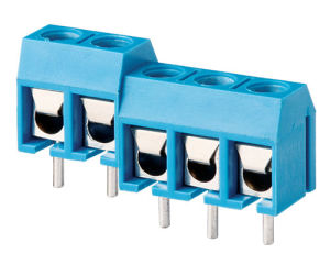
So, the power and relay connectors use these?
Yep, exactly. Should be able to use 3x 2 connector terminals, attaching two using the small slot on the side of the screw terminal module. Just need to be careful to get one with the correct pin spacing.
And that also powers the ESP8266, right? In this case I wonder if having a USB would be better?
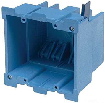
Yep. You can still power everything via USB if you want, however the main reason I have it set up this way is in case you want to have everything in a single enclosure and use
one of these if you are so inclined. Options!
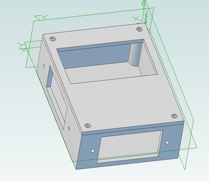
Are those holes under the ESP8266 or does it just look like that? The board certainly would not need much to keep it fixed.
You are correct. The idea is that with the D1 mini you get the male pin headers as well as female. Solder the female pin headers to this board, the male pin headers facing down to the D1 mini, and you're good to go. If something happens to the D1 mini and you need to replace it, just pop it off, pop a new one on, and you're good to go.
This configuration also provides the clearance necessary for the screws. You're still only going to have 2 screws, but as you mentioned, the point is more to keep it from sliding around than anything. Zip ties would probably work just as well.
I'm sure folks using the LCD would like to see an I2C connector. I actually ordered an LCD from Ali so maybe y'all will convert me.
That revision of the board is coming.
")
One with the socket for the level
shifter as you suggested, one with the level shifter integrated on the board.
The only other thing I can see that's missing vs. your list of pinouts is a buzzer. I assume that would change the size and correspondingly the price of the board to place one on the surface?
You got it. I agree though - I've got the space to add connections for the buzzer - worst case it remains unpopulated. I'll add that before the final revision.
What's the reason to power the temp probe from 3v3 rather than 5v? Both are readily available there.
The data lines are all 3v3 so I figured I'd use 3v3 when possible. More practically, if the wiring shorts out somewhere you don't run the risk of burning up the board.
Also, that's what's on the Raspberry Pi GPIO pins which is where my DS18b20 sensors all started out, so I was used to it.
I'm getting real excited about this!
It's getting pretty close, if I may say so myself!


![Craft A Brew - Safale S-04 Dry Yeast - Fermentis - English Ale Dry Yeast - For English and American Ales and Hard Apple Ciders - Ingredients for Home Brewing - Beer Making Supplies - [1 Pack]](https://m.media-amazon.com/images/I/41fVGNh6JfL._SL500_.jpg)