Native ESP8266 BrewPi Firmware - WiFi BrewPi, no Arduino needed!

Homebrew Talk - Beer, Wine, Mead, & Cider Brewing Discussion Forum

Help Support Homebrew Talk - Beer, Wine, Mead, & Cider Brewing Discussion Forum:

This site may earn a commission from merchant affiliate links, including eBay, Amazon, and others.
OK this is really getting me down.

I've been trying to flash the ESP8266 but it keeps coming up with the same error which I can't find an answer for:

A fatal error occurred: Digest mismatch: expected 83C43BAD12A80DDF40BE25F293C7508C, got 14CF401E53384891B41A2291C31AB19E

The command I'm using btw: sudo esptool.py --port /dev/ttyUSB0 write_flash -fm=dio -fs=32m 0x00000 /home/brewpi/esp8266/bin/brewpi-esp8266.v0.2.wifi.bin


I've had a look through the python script and it looks like this is in a couple places and it's not very clear which one it could be, and I'm not clear where the digests come from.

Does anyone know what I'm looking at here?

Is there some log I can look at with some more descriptive error messages?

I was hoping to get my first ever brew done tomorrow, looks like I'll be starting this without temp control, at least to begin with.

edit:
Just to be completely clear here is the full output:
"
pi@pizero:/home/brewpi/esp8266/bin $ sudo esptool.py --port /dev/ttyUSB0 write_flash -fm=dio -fs=32m 0x00000 /home/brewpi/esp8266/bin/brewpi-esp8266.v0.2.serial-wifi-headers.bin
esptool.py v1.1
Connecting...
Running Cesanta flasher stub...
Flash params set to 0x0240
Writing 344064 @ 0x0... 344064 (100 %)

A fatal error occurred: Digest mismatch: expected 83C43BAD12A80DDF40BE25F293C7508C, got 14CF401E53384891B41A2291C31AB19E

"

Thanks,
Matt
 
Last edited:
Your showing 2 different files.

"brewpi-esp8266.v0.2.wifi.bin" and "brewpi-esp8266.v0.2.serial-wifi-headers.bin"

I believe its the first one you should be using. What esp8266 are you using or where did you get it from.

Not sure I'll be a lot of help seeing as how I haven't been able to get everything completely working. However I have been successful at flashing the esp8266. One thing that was causing me big problems was not supplying enough power to the pi.
did you flash sudo esptool.py --port /dev/ttyUSB0 write_flash -fm=dio -fs=32m 0x00000 /home/brewpi/esp8266/bin/brewpi-esp8266.v0.2.wifi.bin
 
Sorry, the trace is from two different attempts. I took a chance that another binary would work. But no luck. I've got the WeMos D1 mini (V2 I think).
 
Any chance of getting the syntax for a full flash ... and the super secret
password or pointed to a general area with the information I did a bit of search but couldn't find anything. Sorry for being so lame.

Alternatively, now that I think about it, what I should do/have done is create a version of the firmware called "force reset" which does nothing but reset the WiFi credentials and then blink the LED annoyingly. Project for tonight!

This is now done, and added to GitHub. Sorry for the delay.

Changes in this version - Added "wifi-reset.bin" firmware (which resets your WiFi credentials) and deleted the "serial with wifi headers" firmware (which was a poor way of implementing wifi-reset).
 
What command do I use to locate the esp8266 on the raspberry pi? I dont think the RPI is seeing my esp8266.

I think you figured this out already (slowly making my way through the latest responses in the thread) but if anyone else comes across this issue, the solution is step 3 in this file.

Ok I hit a new bump in the road.I was able to flash the 8266 while it was connected to the RPI and the RPI is connected to an Ethernet cable and can see it in my windows wireless connections - so I know its alive and doing it's thing.
I'm having problems with the RPI and 8266 working together.When I unplug the Ethernet cable the RPI goes off line but the 8266 is still connected online.

Again - You may have resolved this already, but this is expected behavior. You connect the ESP8266 to your Raspberry Pi to flash it, and then once it's flashed the ESP8266 will connect to the internet (or, create an access point) all on it's own. The Raspberry Pi and the ESP8266 will only connect via WiFi once BrewPi (and the firmware) is configured.

This means that you need to leave your Raspberry Pi connected to your network in some fashion in order for them to talk.

Also, what are the three different bins exactly?

I'm cheating a bit here, because I just changed what the three firmware versions are:
brewpi-esp8266.v0.2.serial.bin - Functions exactly like the Arduino firmware. Connects via serial (not WiFi).
brewpi-esp8266.v0.2.wifi.bin - The WiFi firmware. This is probably what you want.
wifi-reset.bin - If you forget your access point name, flashing this firmware will cause the ESP8266 to forget the WiFi credentials on next reboot. Makes it easier to reconnect to the network.
 
Thanks -I think I'm going to reload and start over. Even after I re scan my wireless connections on my windows computer the esp8266 doesn't show up.

It won't show up after you configure it to connect to your wireless. The reason it shows up the first time is because it is in AP mode (access point). When you configure it, it becomes like every other computer on your network.

What LBussy said... Once the WiFi is configured the first time, it remembers your settings. If you need to reset them, use the new wifi-reset.bin firmware (to download, you will need to re-pull from GitHub).
 
Sorry, the trace is from two different attempts. I took a chance that another binary would work. But no luck. I've got the WeMos D1 mini (V2 I think).

I have never seen that error message before. I have another D1 mini en-route (should be here soon - it took a good 2 weeks to get to the US, but tracking shows it in NYC!) - as soon as it arrives I'll see if I can recreate the issue you're showing.
 
No still stuck on not being able to install any of the discovered devices. Was waiting for some help. But either I'm totally an idiot and missing something obvious or no one knows how to fix it. I'm leaning towards the first one but haven't had any time to look at it again for the obvious errors on my part.

Were you able to get anything installed? I'm having trouble now getting my heater and cooler installed.

Hmm... I'm not having success duplicating this issue on my install at the moment. Can you post a screenshot showing the chamber settings you have in BrewPi's interface? I'll do the same momentarily for the settings that work.
 
Where did you find the breadboard RJ12 connector? The only one I have found is ridiculously priced.

Apologies for the delay on this!

You're right - the breakout boards are ridiculous. I just designed a quick one & posted to PCBs.io -- If you're willing to bust out the soldering iron, you can buy 4 RJ-11 breakout PCBs for $2.75 (total!) here:
https://PCBs.io/share/8AvVr

I've used this footprint with the
95001-6P6C jacks available on AliExpress. This link is $3.76/20.

All said, you're paying $6.51 total, shipped for enough parts to build at least 4 or $1.63/ea.

If you really want to cheat with the math, it's $0.88/ea. :)

(Full disclosure - If you order that through PCBs.io, I get a (small) credit on their site. That said, the real goal was to make it easy to order - if you have a preferred fab house, let me know & I'll happily find a place to upload the Eagle files. Alternatively, it's a pretty simple schematic. :))

For testing I used a RJ11 plug-to-socket phone line extension. It cost about $2. I cut the cord to leave the socket with a 30cm pigtail, then split out the wires inside and stripped and tinned them. At that point you can either plug them into a breadboard, or solder them on to some DuPont female connectors to plug directly onto the Pi GPIO.

https://www.amazon.com/dp/B001UL3EPQ/?tag=skimlinks_replacement-20

You can also use RJ11 keystone jacks and your own wire.

https://www.amazon.com/dp/B01DQ6R6NS/?tag=skimlinks_replacement-20

Or use one of these. The wires are long enough to plug into a breadboard.

https://www.amazon.com/dp/B008NCDMCA/?tag=skimlinks_replacement-20

(Amazon links just for illustration)
 
Last edited by a moderator:
Wow you've been busy! Thanks for sharing the RJ12 jack build. I'll be able to use a few of those no matter what I'm sure.

Here's a question then since you are back: What's the end game here? What will this be when you are done?

A wireless networked temp controller is on my wishlist for sure, I just don't want to go "all in" on something that does not look like your end vision. I realize you have no responsibility to me or anyone else, but it would also be silly of me to drop one of these on every fridge I have if you are going to change over to a different card next week - I'd be stuck without any hope of help.

@pocketmon 's work is also interesting but I think I'd be sorry long term to give up the built-in graphing. The work-around he has currently, especially not being able to use https as part of it, is giving me some pause. BrewPi's graphing is pretty robust and to re-write that in something else is unlikely to yield something as robust and feature-rich.

Anyway, hopefully you get what I mean. I know this is not your job, I'm just wondering where at least one other person on this earth is headed so I won't be alone. :mug:
 
Here's a question then since you are back: What's the end game here? What will this be when you are done?

Anyway, hopefully you get what I mean. I know this is not your job, I'm just wondering where at least one other person on this earth is headed so I won't be alone. :mug:

Honestly, we're almost there. The goal is to implement BrewPi firmware on an ESP8266. If there are bugs in the BrewPi firmware then potentially I'll fix those, but otherwise the goal is to support almost all of the functionality that the Arduino firmware supports as implemented -- and that's about it. The only thing that I'm not pushing to support at the moment is the rotary encoder due to pin limitations, but that might be added later.

That said - if there were features that people wanted that would best be implemented on the firmware I'm open to forking the project and looking to implement them, but there would still be the BrewPi-compatible fork. Most feature requests seem to be things that would best live in BrewPi-www, however - not the firmware.
 
Honestly, we're almost there. The goal is to implement BrewPi firmware on an ESP8266. If there are bugs in the BrewPi firmware then potentially I'll fix those, but otherwise the goal is to support almost all of the functionality that the Arduino firmware supports as implemented -- and that's about it. The only thing that I'm not pushing to support at the moment is the rotary encoder due to pin limitations, but that might be added later.
And without the encoder (personally) I have no need of the display. I'm probably in the minority there. Maybe I just need to get off my duff and buy one and I'll think differently.

Is the door switch implemented?

That said - if there were features that people wanted that would best be implemented on the firmware I'm open to forking the project and looking to implement them, but there would still be the BrewPi-compatible fork. Most feature requests seem to be things that would best live in BrewPi-www, however - not the firmware.
In that case the "features" I'm looking for are physical. I'd like to see a simple shield with an RJ-12 jack (with pullup resistor,) pins for the relay connections, and I suppose a few pins and the bi-directional logic converters for the I2C since there's folks that will use it.

Why do most folks seem to prefer those dupont connectors over screw terminals? I can be convinced to think differently about them I suppose but screw terminals seem more durable to me. Size thing?

Please, for the ham-fisted like me, through-hole soldering on this. :)

If I knew how to design a board I certainly would help with this. It seems like for someone with the knowledge/ability this should be among the easier things to do.

Hrm ... did you ever put in the ability to re-name the ESP8266 host? I can't think of anything else feature-wise.

I'd be more than happy to assist how I can. That may consist solely of documentation if needed.
 
Hmm... I'm not having success duplicating this issue on my install at the moment. Can you post a screenshot showing the chamber settings you have in BrewPi's interface? I'll do the same momentarily for the settings that work.

I'll probably try my hand at it again either tonight or tomorrow. I've been spending my time remaking an enclosure for this project finally (after a year of having my Arduino and Raspberry Pi screwed into my ferm chamber lid!) so none of the components have been powered up. Though I did get as far as trying to pin things out and heard a "pop" so I may have fried something...hopefully not!
 
Hmm... I'm not having success duplicating this issue on my install at the moment. Can you post a screenshot showing the chamber settings you have in BrewPi's interface? I'll do the same momentarily for the settings that work.

I give the 2 temp probes device 0 and 1 change the other settings as per the screenshot click apply on each one, the stderr.txt log is shown below. Refresh device list and the device slots on the temp probes go back to unassigned

Aug 16 2016 13:32:06 Fresh start! Log files erased.
Aug 16 2016 13:32:15 Installed devices received: []
Aug 16 2016 13:32:15 Available devices received: [{"a": "28FF7E366914045B", "c": 1, "b": 0, "d": 0, "f": 0, "i": -1, "h": 2, "j": 0.0, "p": 12, "t": 0}, {"a": "28FF173B641403B7", "c": 1, "b": 0, "d": 0, "f": 0, "i": -1, "h": 2, "j": 0.0, "p": 12, "t": 0}, {"c": 1, "b": 0, "d": 0, "f": 0, "i": -1, "h": 1, "p": 2, "t": 0, "x": 1}, {"c": 1, "b": 0, "d": 0, "f": 0, "i": -1, "h": 1, "p": 0, "t": 0, "x": 1}, {"c": 1, "b": 0, "d": 0, "f": 0, "i": -1, "h": 1, "p": 14, "t": 0, "x": 1}]
Aug 16 2016 13:33:07 Finding a log message here should not be possible, report to the devs!
Aug 16 2016 13:33:07 Line received was: Dev Chamber: 1, Dev Beer: 1, Dev Function: 9, Dev Hardware: 2, Dev PinNr: 12
Aug 16 2016 13:33:07 Controller debug message: ERROR 8: Cannot assign device type 0 to hardware 2
Aug 16 2016 13:33:07 Cannot process line from controller: target Chamber: 39, target Beer: 0, target Function: 1073674032, target Hardware: 1, target PinNr: 10
Aug 16 2016 13:33:07 Controller debug message: ERROR 3: Device defifination update specification is invalid
Aug 16 2016 13:33:07 Finding a log message here should not be possible, report to the devs!
Aug 16 2016 13:33:07 Line received was: Dev Address: (;d, Target Address: @ ?0?
Aug 16 2016 13:33:07 Device updated to: {"i":1,"t":0,"c":39,"b":0,"f":48,"h":1,"d":32,"p":10,"x":-74}
Aug 16 2016 13:41:24 Installed devices received: []
Aug 16 2016 13:41:24 Available devices received: [{"a": "28FF7E366914045B", "c": 1, "b": 0, "d": 0, "f": 0, "i": -1, "h": 2, "j": 0.0, "p": 12, "t": 0}, {"a": "28FF173B641403B7", "c": 1, "b": 0, "d": 0, "f": 0, "i": -1, "h": 2, "j": 0.0, "p": 12, "t": 0}, {"c": 1, "b": 0, "d": 0, "f": 0, "i": -1, "h": 1, "p": 2, "t": 0, "x": 1}, {"c": 1, "b": 0, "d": 0, "f": 0, "i": -1, "h": 1, "p": 0, "t": 0, "x": 1}, {"c": 1, "b": 0, "d": 0, "f": 0, "i": -1, "h": 1, "p": 14, "t": 0, "x": 1}]

devices.png
 
Still having the same issue, I'll PM you (Thorrak) with my DDNS address if you want to try mucking around with it, just please don't wreck my device! :mug:
 
I give the 2 temp probes device 0 and 1 change the other settings as per the screenshot click apply on each one, the stderr.txt log is shown below. Refresh device list and the device slots on the temp probes go back to unassigned

Aug 16 2016 13:32:06 Fresh start! Log files erased.
Aug 16 2016 13:32:15 Installed devices received: []
Aug 16 2016 13:32:15 Available devices received: [{"a": "28FF7E366914045B", "c": 1, "b": 0, "d": 0, "f": 0, "i": -1, "h": 2, "j": 0.0, "p": 12, "t": 0}, {"a": "28FF173B641403B7", "c": 1, "b": 0, "d": 0, "f": 0, "i": -1, "h": 2, "j": 0.0, "p": 12, "t": 0}, {"c": 1, "b": 0, "d": 0, "f": 0, "i": -1, "h": 1, "p": 2, "t": 0, "x": 1}, {"c": 1, "b": 0, "d": 0, "f": 0, "i": -1, "h": 1, "p": 0, "t": 0, "x": 1}, {"c": 1, "b": 0, "d": 0, "f": 0, "i": -1, "h": 1, "p": 14, "t": 0, "x": 1}]
Aug 16 2016 13:33:07 Finding a log message here should not be possible, report to the devs!
Aug 16 2016 13:33:07 Line received was: Dev Chamber: 1, Dev Beer: 1, Dev Function: 9, Dev Hardware: 2, Dev PinNr: 12
Aug 16 2016 13:33:07 Controller debug message: ERROR 8: Cannot assign device type 0 to hardware 2
Aug 16 2016 13:33:07 Cannot process line from controller: target Chamber: 39, target Beer: 0, target Function: 1073674032, target Hardware: 1, target PinNr: 10
Aug 16 2016 13:33:07 Controller debug message: ERROR 3: Device defifination update specification is invalid
Aug 16 2016 13:33:07 Finding a log message here should not be possible, report to the devs!
Aug 16 2016 13:33:07 Line received was: Dev Address: (;d, Target Address: @ ?0?
Aug 16 2016 13:33:07 Device updated to: {"i":1,"t":0,"c":39,"b":0,"f":48,"h":1,"d":32,"p":10,"x":-74}
Aug 16 2016 13:41:24 Installed devices received: []
Aug 16 2016 13:41:24 Available devices received: [{"a": "28FF7E366914045B", "c": 1, "b": 0, "d": 0, "f": 0, "i": -1, "h": 2, "j": 0.0, "p": 12, "t": 0}, {"a": "28FF173B641403B7", "c": 1, "b": 0, "d": 0, "f": 0, "i": -1, "h": 2, "j": 0.0, "p": 12, "t": 0}, {"c": 1, "b": 0, "d": 0, "f": 0, "i": -1, "h": 1, "p": 2, "t": 0, "x": 1}, {"c": 1, "b": 0, "d": 0, "f": 0, "i": -1, "h": 1, "p": 0, "t": 0, "x": 1}, {"c": 1, "b": 0, "d": 0, "f": 0, "i": -1, "h": 1, "p": 14, "t": 0, "x": 1}]

I am no BrewPi expert, but as far as I know, the "chamber sensor" should have "beer" set to none or zero, never "Beer 1"
 
Apologies for the multi-quotes below!

And without the encoder (personally) I have no need of the display. I'm probably in the minority there. Maybe I just need to get off my duff and buy one and I'll think differently.

I love having the LCD, mainly for the feedback it provides as to whether or not the temperature control is actually working. It's entirely a preference though - I could probably live without it once I grew to trust the software.

Is the door switch implemented?

I don't believe so, but it's a simple addition. I'll make sure it gets added soon.

In that case the "features" I'm looking for are physical. I'd like to see a simple shield with an RJ-12 jack (with pullup resistor,) pins for the relay connections, and I suppose a few pins and the bi-directional logic converters for the I2C since there's folks that will use it.

I'm working on it. I did this for another project (post coming soon!) and am most of the way there for this one. Benefit of the D1 Mini is the small footprint, which makes PCBs dirt cheap.

Why do most folks seem to prefer those dupont connectors over screw terminals? I can be convinced to think differently about them I suppose but screw terminals seem more durable to me. Size thing?

Basically. Size, and convenience. I'm with you for anything power-related, but for "signal" connections I like the fact that I can quickly make a 4-pin cable (or 2 pin, or 14 pin, or...). Basically it's an inexpensive standard for low-voltage connections that most pre-built boards support.

Please, for the ham-fisted like me, through-hole soldering on this. :)

Agreed -- except for the i2c logic level conversion. Cheapest/easiest way to implement is SMD. If you don't care about the LCD though, you could just skip adding that part, however. I won't judge (and neither will the board!)

Hrm ... did you ever put in the ability to re-name the ESP8266 host? I can't think of anything else feature-wise.

Not yet - and agreed. It would be a good feature. v3? v4? It's coming, though I can't say when.

I'd be more than happy to assist how I can. That may consist solely of documentation if needed.

Feel free! Any updates/forks are always welcome. That's one of the benefits of open source!
 
No still stuck on not being able to install any of the discovered devices. Was waiting for some help. But either I'm totally an idiot and missing something obvious or no one knows how to fix it. I'm leaning towards the first one but haven't had any time to look at it again for the obvious errors on my part.

Were you able to get anything installed? I'm having trouble now getting my heater and cooler installed.

I was able to poke at this a bit, and it appears the issue is specifically when assigning a sensor to "beer". After resetting the controller's eeprom I was able to assign the door/heater/cooling functions as well as the chamber sensor. When assigning the beer sensor I got the error message you guys are seeing.

I'm going to dig into this further tonight/tomorrow. I have the day off tomorrow, so should have a fix soon. :)
 
Apologies for the multi-quotes below!
I am a fan of multi-quotes for clarity! :ban:

Agreed -- except for the i2c logic level conversion. Cheapest/easiest way to implement is SMD. If you don't care about the LCD though, you could just skip adding that part, however. I won't judge (and neither will the board!)
I'd think the easiest solution there would be to buy the $0.75 board and pin that in?

Feel free! Any updates/forks are always welcome. That's one of the benefits of open source!
I need to read a GITHub primer before venturing down that path. I'm sure someone has one.
 
I'd think the easiest solution there would be to buy the $0.75 board and pin that in?

Too logical. Not over engineered enough. This actually is a great idea to remove any need for SMD components. The only concern would be if the manufacturer decided to change form factors for their board, but given the tiny minimum order volumes on these things that just means order the level shifter board before the PCB.

Now, I just have to learn how to create new parts in Eagle.
 
Side note - thanks Jabib for sending this across. It helped immensely!

Glad to hear! I figured you trying to recreate would be harder than just swinging by my setup.

Too logical. Not over engineered enough.

Exactly! When is anything we do as homebrewers easy? Seems I always trade ease in one area for headache in another! I could have just bought a new RPi and left my BrewPi alone, but where's the fun in that?!
 
After your tinkering, I was able to assign Device 0 to Chamber 1, Beer 1, Beer Temp. I think at this point I might be able to just wire everything up to the ESP8266, throw it in the enclosure, and just continue to muck around on the RPi side for the web server. I'll report back later to let you know how it goes.

Thank you for the help, and let me know if there's anything else you want to test given that my install had some issues.

Interesting -- Maybe that's the issue as I don't think I was selecting a beer.

It's a deviation from the original source, but does anyone see any reason why I shouldn't have the firmware default the beer number for beer sensors to 1? (And, for that matter, default the beer/chamber sensors across the board)
 
I only have this controlling a single chamber and single beer, so I'm ok with that.

As for selecting the beer, I wasn't able to do any of those assignments before, so "resetting the eeprom" must have did the trick. How is that done, since I think others could benefit from that.
 
hey guys just a thought on the front end side, I really don't get the smaller is better with displays, my brewery is huge compared to these tiny 2 inch lcd displays which i cant even see in the sun, how about we port to a tablet with an easy to use touch screen layout like a windows 10 tablet squares type so fat fingered people can actually use it? I know its either going to be a web page or a coded phone type app but just a thought for the future,

you know testing in a lab under the best lighting vs the real world is too different things, I hope this can go in that direction :)

The ESP8266 can accept multiple connections at once, if I recall correctly. Nothing would prevent you from coding a tablet app that connects to your device, reads the LCD content (it's sent JSON encoded, so should be easy to decode) and then transform that into whatever type of display you like.

As far as touchscreen controls, the same thing applies. Commands are sent from the BrewPi-www interface to the firmware. The firmware then executes the commands, and sends the status back to the BrewPi-www interface. Nothing prevents you from writing a tablet app that would send commands to the ESP8266. The firmware would then execute those, and send back to the BrewPi-www interface.

Ultimately, everything I described above is in the vein of 'changes to brewpi-www', however, which is beyond the scope of this specific project. The beauty of elco's model is that it's open source, however, so nothing is stopping you from going out there and creating what you want!
 
I only have this controlling a single chamber and single beer, so I'm ok with that.

As for selecting the beer, I wasn't able to do any of those assignments before, so "resetting the eeprom" must have did the trick. How is that done, since I think others could benefit from that.

See - that's the thing. As currently built, I think that BrewPi only supports 1 chamber/1 beer at the moment anyways. I may be wrong, but basically this is functionality that doesn't work at the best of times, and gets in its own way at the worst.

As far as resetting the EEPROM, I believe it was under "Advanced Configuration" in the BrewPi maintenance section, near the very bottom. I'm not near an installation at the moment so I can't check, but I know there was a button that read something similar to "Reset controller to factory settings". That's what I clicked.
 
Ah alright! I actually avoided touching those functions thinking that since BrewPi is written for Arduino via USB that it would soft-brick the communication between the RPi and ESP.

No still stuck on not being able to install any of the discovered devices. Was waiting for some help. But either I'm totally an idiot and missing something obvious or no one knows how to fix it. I'm leaning towards the first one but haven't had any time to look at it again for the obvious errors on my part.

On the BrewPi page, it's under Maintenance Panel >> Advanced Settings >> Control constants window. All the way at the bottom it says
With the button below, you can reset the entire controller to factory defaults.
This will reset all settings and will remove all installed devices.
Try clicking on that and see if you can install your sensors!
 
Does anyone have a 3D model for a case to 3D print or a recommendation for a packaging system?

Additionally, every once in a while, my screen shows a bunch of garbled information. Not sure what is going on, but if I reset the system it goes away for about 24 hours. I have a known range problem with my wifi, but doubt this could be the problem. Does anyone else have these problems?
 
I'm using a PVC enclosure from Home Depot which ran me around $10. Depending on how much stuff you're trying to cram in the case, you could get away with something small, but I have external mounted outlets, lights, and cat5 jack for temp probes. I know if you search thingiverse.com you can find a brewpi case, but I'm not sure what you get in that.
 
So, for a I2C logic level converter, you can literally do that with two MOSFETS, 2N7000 is very typical part to use for this. Can be SMD or through hole... since I am assuming that you will all run a WEMOS from a 5V USB supply, both voltages are present at whatever daughterboard you need to design.

http://www.hobbytronics.co.uk/mosfet-voltage-level-converter

Has a nice example of this. Even two TO-92 cased transistors and four leaded resistors take up very little room... But on the other hand, what makes the group afraid of soldering on (larger) SMT parts in the first place. Two decent quality soldering irons and some flux and you are golden. It's not hard to do unless you start talking QFN or BGA's...
 
Does anyone have a 3D model for a case to 3D print or a recommendation for a packaging system?

https://www.thingiverse.com/thing:360709 is the case I was thinking about.
There doesn't seem to be much in the way of ESP8266 cases/enclosures on Thingiverse, but there is a model of one if you want to try and move the mounting screws to accommodate that case, but I don't think it's worth the effort personally.
 
Okay ... HOW do you get the wires from the probes into the RJ-11 plugs? I bought some today and the insulation is way too thick. Am I missing something?
 
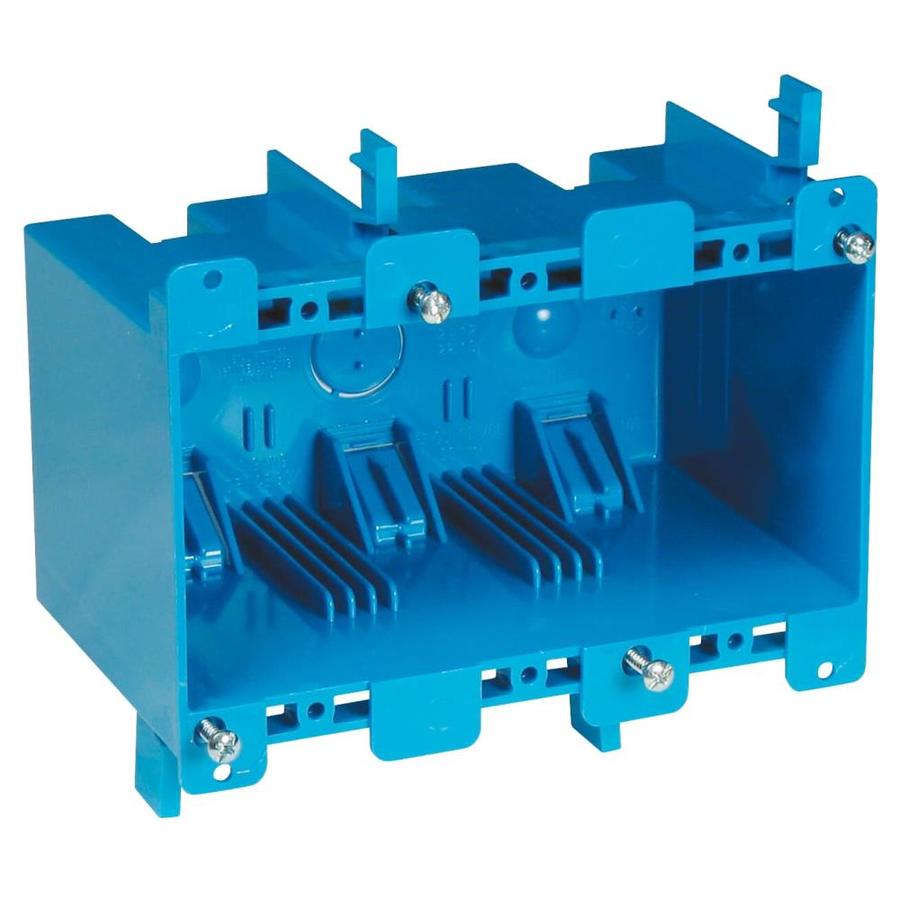
I'm going to try and use an OLD WORK electrical box as a case

Are you going to put it in the wall too? That would be a really impressive way to hide it all. I'm...somewhat jealous I didn't think of that. I don't have a finished wall so I guess I'm not really missing out. Good luck with that!


Okay ... HOW do you get the wires from the probes into the RJ-11 plugs? I bought some today and the insulation is way too thick. Am I missing something?

My plan is to take some Cat5e cable (telephone wire in your case) and make a mid-wire splice, and just make direct connections in the enclosure from the jack.
 
[...]Additionally, every once in a while, my screen shows a bunch of garbled information. Not sure what is going on, but if I reset the system it goes away for about 24 hours. I know range problem with my wifi. Does anyone else have these problems?

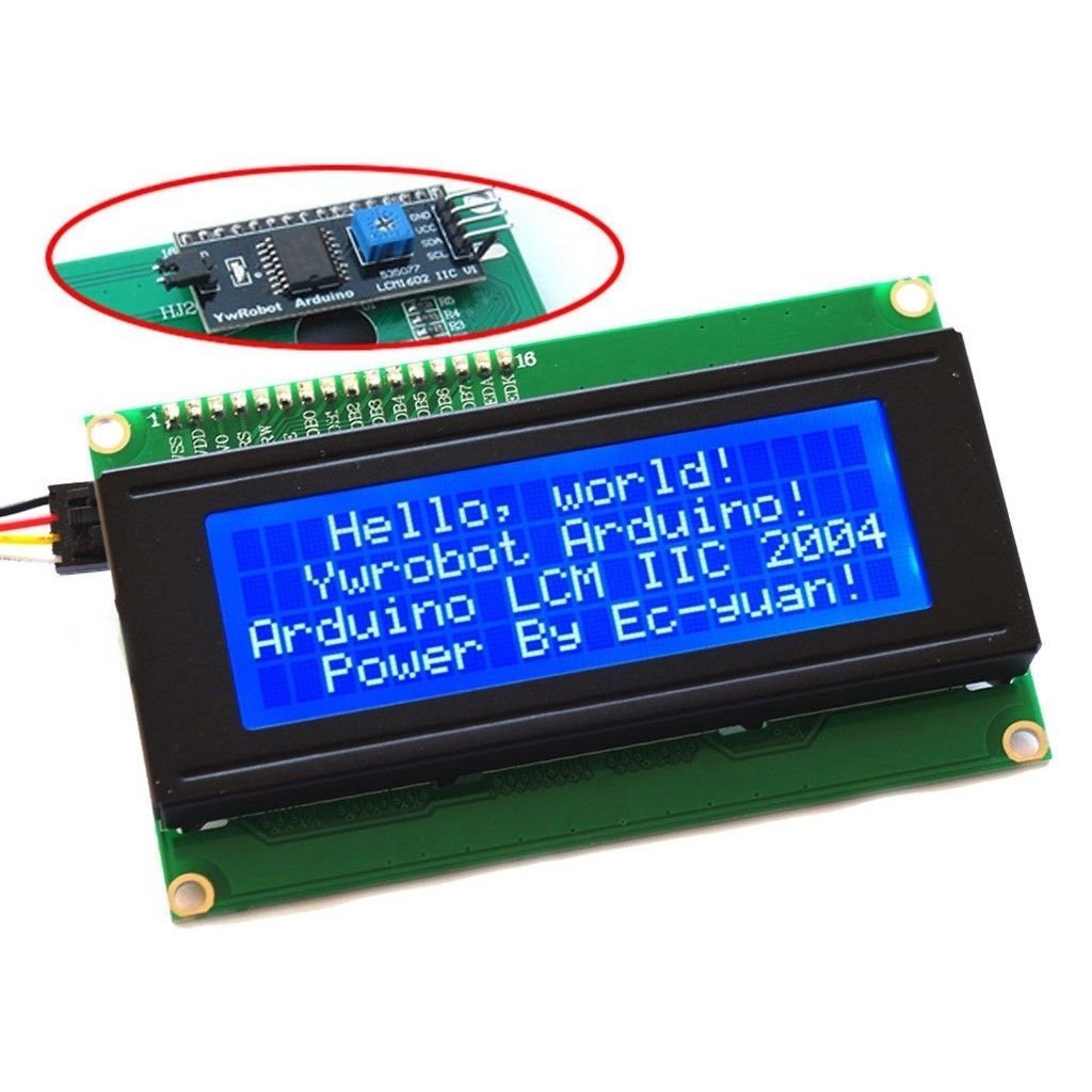
Is this the 20x4 white-on-blue LCD display with the I2C backpack, like this?
61XYuD4yixL._SL1024_.jpg


Cheers!
 
Back
Top