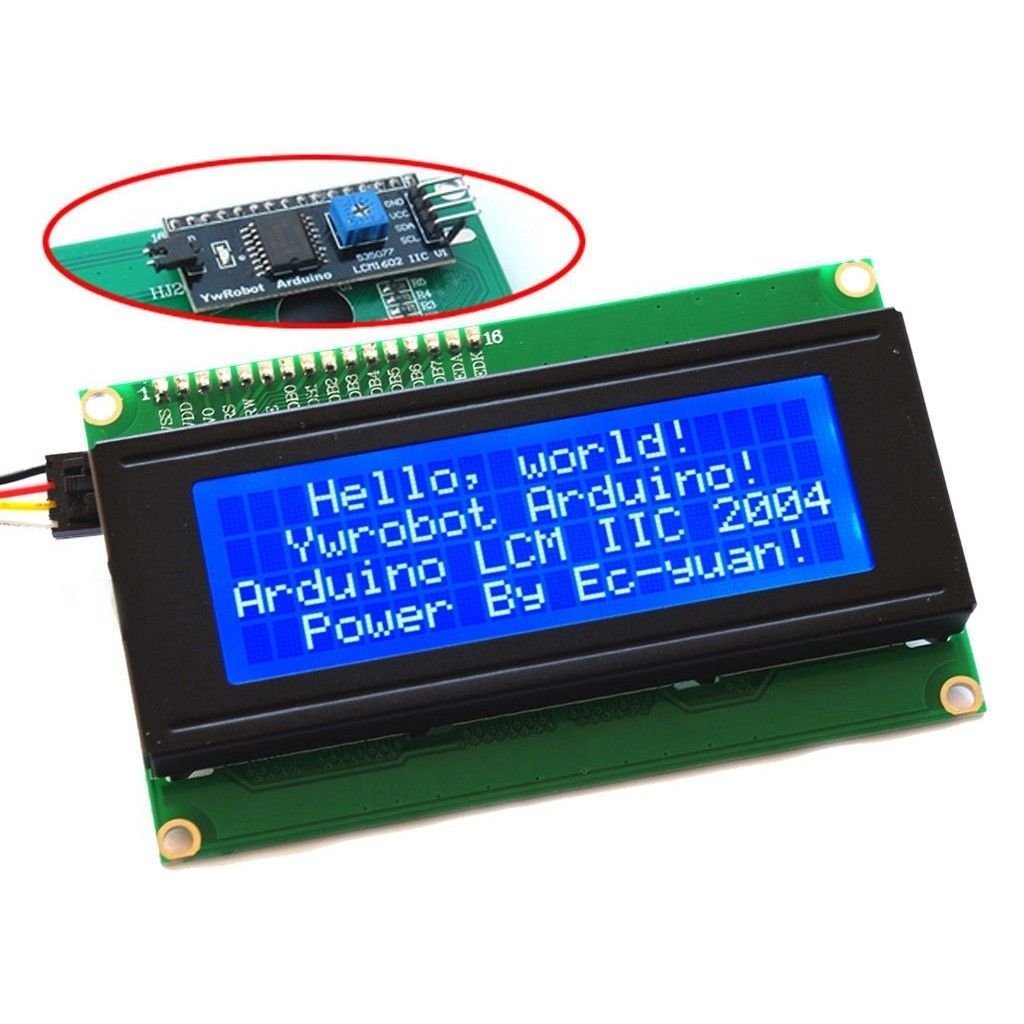
Is this the 20x4 white-on-blue LCD display with the I2C backpack, like this?
Cheers!
This is the one that I bought off of amazon
I have a second one I could try. I should do that.


Last edited by a moderator:

Is this the 20x4 white-on-blue LCD display with the I2C backpack, like this?
Cheers!
Okay ... HOW do you get the wires from the probes into the RJ-11 plugs? I bought some today and the insulation is way too thick. Am I missing something?
https://www.thingiverse.com/thing:360709 is the case I was thinking about.
There doesn't seem to be much in the way of ESP8266 cases/enclosures on Thingiverse, but there is a model of one if you want to try and move the mounting screws to accommodate that case, but I don't think it's worth the effort personally.
I never thought about installing it in a wall -that might be cool if you use Raspberry Pints.Are you going to put it in the wall too? That would be a really impressive way to hide it all. I'm...somewhat jealous I didn't think of that. I don't have a finished wall so I guess I'm not really missing out. Good luck with that!
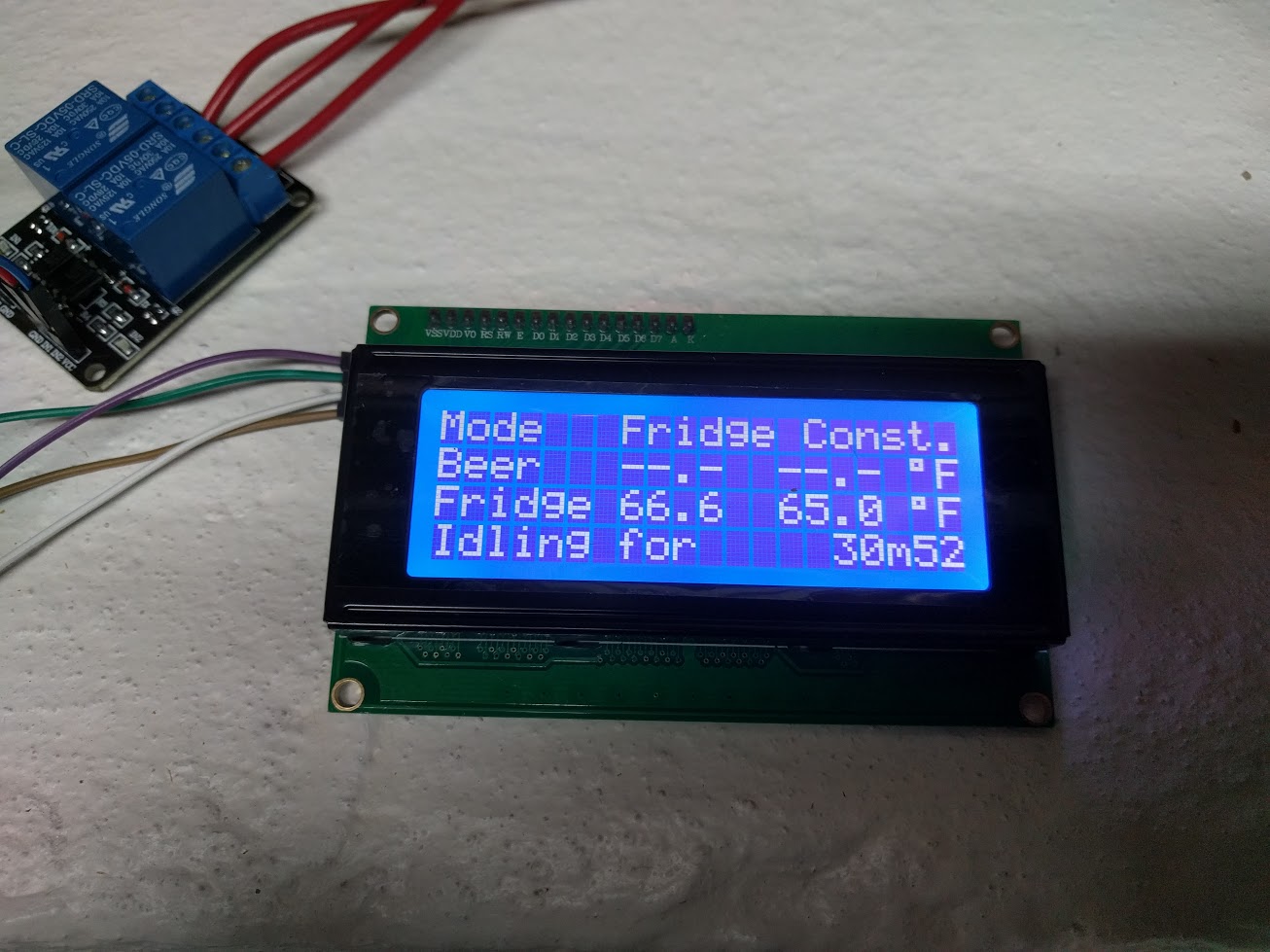
This seems like the classic LCD scrambling problem.
This seems like the classic LCD scrambling problem.


![Craft A Brew - Safale S-04 Dry Yeast - Fermentis - English Ale Dry Yeast - For English and American Ales and Hard Apple Ciders - Ingredients for Home Brewing - Beer Making Supplies - [1 Pack]](https://m.media-amazon.com/images/I/41fVGNh6JfL._SL500_.jpg)


This seems like the classic LCD scrambling problem.
")
That's where I was leading him
It's hardly a revelation, but it confirms what I've been saying all along: these screens are susceptible to voltage noise, which has nothing to do with the various "shield" designs...
Cheers!
So I feel like I'm 95% there.
I've connected both DS18B20 to a Cat5e cable. I decided that I needed to make myself some standard so I don't mess this up since I'm looking to use this same setup for my Strangebrew Elsinore panel. I used the pair of orange as 3.3v, the pair of blue as Data, and the pair of brown as Ground. Green pair is unused. I shoved the 4.7kOhm resistor in the push down RJ45 jack.
I've also got everything wired up right on the high side. I have three LED lights (Power - White, Heat - Red, Cool - Blue) with a toggle switch to shut the lights off completely if I want.
I ripped apart an old cell phone charger and took the circuitry out and it's in the enclosure to power the ESP8266.
My low side (5v & 3.3v) connections are correct as far as I can tell (Pin Vin = 5v and Pin 3.3v = 3.3v)...
BUT when I power everything on, the Sainsmart board crackles, both lights flash, and then shut down. The ESP8266 I believe shuts down as well when this happens, unless I press the reset button. I can push the reset button and it'll keep crackling (and this happens without the high side 120v power connected).
I disconnected the 5v lead from the Sainsmart board, restarted everything (RPi, ESP8266) and after a couple seconds connected the 5v lead, and it works. I go into BrewPi, tell the controller that pins D3 and D4 aren't inverted (testing their wiring) and the relay board switches them on without issue. I press the reset button on the ESP8266 and it crackles and shuts down...
So I feel confident in my wiring, but I'm a bit concerned with my Sainsmart board. I'm going to bring it down and test it out with the Arduino again, and if that doesn't work, I'm a bit worried about the ESP8266...
Hopefully this post (while a bit long) is both helpful for others planning a build, and gives enough info that someone more versed than I am can help me get across this finish line. Cheers!
Hmm. Whats the best way to handle that, though? Capacitors on the +5/+3.3 lines?
Ah, you probably need to remove the jumper and connect 5V to the relay coil (JD-VCC) and 3.3V to the optoisolator (VCC).It's JD-VCC/VCC I believe that's where it was set from factory and what worked on the Arduino
Ah, you probably need to remove the jumper and connect 5V to the relay coil (JD-VCC) and 3.3V to the optoisolator (VCC).
Shaving the insulation sounds ... what's the right word ... how would you describe sanding your man-bits with a random orbit sander? That word would apply here.You have two choices. One is to shave a little of the insulation from each wire until it fits. The other is to use another connector.
If have used both approaches. Most recently I used a 3.5mm stereo plug on the sensor cable and made a pigtail adapter from a 3.5mm stereo socket to an RJ 11 plug.
Shaving the insulation sounds ... what's the right word ... how would you describe sanding your man-bits with a random orbit sander? That word would apply here.
The stereo jack pigtail sounds like a good idea. How exactly are you wiring that? Which wire to where? Ground on the sleeve, data on the ring, Vcc on the tip? Which side gets which end of the plug?
This might be a good time to ask how folks are using the wiring in the phone cables too so that I might not have to do this again. I am assuming that folks would use:
Mostly I guess I'm interested in how @Thorrak is doing this part since he'll be doing the boards (so I don't have to re-do them all,) but I'm curious if anyone chose anything different.
- Red - Vcc
- Black - Ground
- Yellow - Data
My thought as to why it worked is D3 and D4 are likely set low on a reset, and only go high when the firmware is initialized.
Okay so I need to do some reflective listening on that one. This means that my sensor to phone cord connections will look like this?@ame actually sent over some documents when I asked him the same question -- apparently there's a defacto standard that people have been using:
https://datasheets.maximintegrated.com/en/ds/DS9097U-DS9097U-S09.pdf
Basically, it's:
Door - Yellow (see note below)
Gnd - Green
Data - Red
3v3 - Black
Yes - this means that we are not running the sensors in parasite mode.
On the door sensor - Again, stole the idea from @ame - Given that this uses RJ-11, you can just hook up telephone jack splitters to wire up multiple sensors. If you save one jack & break out the wires, you can use it to wire up your door sensor and save yourself additional wires coming out of your fermenter.
Sensor        <-> RJ-11
-----------------------
Red (Vcc)     <-> Black
Black (Gnd)   <-> Green
Yellow (Data) <-> RedRelay Vcc -> Vin 5v
Relay In1 -> 3.3v
Relay In2 -> 3.3v
Relay Gnd -> GndRelay Vcc -> Vin 5v
Relay In1 -> Gnd
Relay In2 -> Gnd
Relay Gnd -> GndD1 - I2C SCL
D2 - I2C SDA
D3 - Cool
D4 - Heat
D5 - Door
D6 - OneWire Data
D7 - Buzzer (currently unsupported)Not sure what polarity you're using but whichever state is "Off", add weak pull-ups or pull-downs to the two control signals to keep them in the "Off" state while the controller is spinning up...
Cheers!
If I've followed this sub-thread correctly, your IO are as follows:
D1 - I2C SCL
D2 - I2C SDA
D3 - Cool
D4 - Heat
D5 - Door
D6 - OneWire Data
D7 - Buzzer (currently unsupported)
From the page you linked, it turns out the state of GPIO0 and GPIO2 (D3 and D4, respectively) are significant during boot, and both must be pulled high (they show 12K but 10K's would be fine).
Your down-stream implementation of D3 and D4 must account for that, so if your loads will be enabled if D3 and D4 are high at power-up (as required) you might consider sticking inverters in the circuits and going back to "Low = On" in BrewPi...
Cheers!
[...]since the 2 channel relay is on when the pin is set LOW, at boot, the pin being set HIGH would not cause the relay to turn on?

Okay so I need to do some reflective listening on that one. This means that my sensor to phone cord connections will look like this?
Code:Sensor <-> RJ-11 ----------------------- Red (Vcc) <-> Black Black (Gnd) <-> Green Yellow (Data) <-> Red
... and then the door will be Yellow grounding to Green on the phone cable, right?

For what it's worth, this is the schematic I'm using at the moment:
Yeah that's what I've been following from your instructables page, and it works in every situation except during the boot up of the ESP8266 because D3 and D4 seem to be pulled low at boot (or are initially inputs to check for flashing conditions?) before the void setup() gets them set as outputs and High.
Yeah that's what I've been following from your instructables page, and it works in every situation except during the boot up of the ESP8266 because D3 and D4 seem to be pulled low at boot (or are initially inputs to check for flashing conditions?) before the void setup() gets them set as outputs and High.
I hate to switch pin configuration, but D7/D8 instead perhaps? Hmm...
Seems like we are saying the same thing.Below is what mine looks like.
From the top down:
Yellow (4) - Door
Green (3) - Ground
Red (2) - Data
Black (1) - 3v3
The colors aren't important - what is important is the pin order.
Would it be an issue that D7/D8 are a UART TX/RX Pair?
Edit: doesn't appear like it would
Yeah that's what I've been following from your instructables page, and it works in every situation except during the boot up of the ESP8266 because D3 and D4 seem to be pulled low at boot (or are initially inputs to check for flashing conditions?) before the void setup() gets them set as outputs and High.


