You are using an out of date browser. It may not display this or other websites correctly.
You should upgrade or use an alternative browser.
You should upgrade or use an alternative browser.
Native ESP8266 BrewPi Firmware - WiFi BrewPi, no Arduino needed!
- Thread starter Thorrak
- Start date

Help Support Homebrew Talk:
This site may earn a commission from merchant affiliate
links, including eBay, Amazon, and others.
This is the one I got from you - would be nice to know the possible way of doing things with it

That's not a board of my design, unfortunately - none of mine have ICs on them. If you remember where you got it, however, I'd love to see what is on it!
stbernts
Well-Known Member
- Joined
- May 20, 2016
- Messages
- 257
- Reaction score
- 43
That board is for hot side control through BrewManiacEx; from @pocketmon;
Thanks, that is correct, remembered it once you wrote it
")
What board gives me the most for this project then? And what is the benefits?


$176.97
1pc Commercial Keg Manifold 2" Tri Clamp,Ball Lock Tapping Head,Pressure Gauge/Adjustable PRV for Kegging,Fermentation Control
hanhanbaihuoxiaoshoudian


$33.99 ($17.00 / Count)
$41.99 ($21.00 / Count)
2 Pack 1 Gallon Large Fermentation Jars with 3 Airlocks and 2 SCREW Lids(100% Airtight Heavy Duty Lid w Silicone) - Wide Mouth Glass Jars w Scale Mark - Pickle Jars for Sauerkraut, Sourdough Starter
Qianfenie Direct


$7.79 ($7.79 / Count)
Craft A Brew - LalBrew Voss™ - Kveik Ale Yeast - For Craft Lagers - Ingredients for Home Brewing - Beer Making Supplies - (1 Pack)
Craft a Brew


$76.92 ($2,179.04 / Ounce)
Brewing accessories 1.5" Tri Clamp to Ball Lock Post Liquid Gas Homebrew Kegging Fermentation Parts Brewer Hardware SUS304 Brewing accessories(Gas Hose Barb)
chuhanhandianzishangwu


$58.16
HUIZHUGS Brewing Equipment Keg Ball Lock Faucet 30cm Reinforced Silicone Hose Secondary Fermentation Homebrew Kegging Brewing Equipment
xiangshuizhenzhanglingfengshop

$44.99
$49.95
Craft A Brew - Mead Making Kit – Reusable Make Your Own Mead Kit – Yields 1 Gallon of Mead
Craft a Brew

$479.00
$559.00
EdgeStar KC1000SS Craft Brew Kegerator for 1/6 Barrel and Cornelius Kegs
Amazon.com


$22.00 ($623.23 / Ounce)
AMZLMPKNTW Ball Lock Sample Faucet 30cm Reinforced Silicone Hose Secondary Fermentation Homebrew Kegging joyful
无为中南商贸有限公司


$53.24
1pc Hose Barb/MFL 1.5" Tri Clamp to Ball Lock Post Liquid Gas Homebrew Kegging Fermentation Parts Brewer Hardware SUS304(Liquid Hose Barb)
yunchengshiyanhuqucuichendianzishangwuyouxiangongsi


$719.00
$799.00
EdgeStar KC2000TWIN Full Size Dual Tap Kegerator & Draft Beer Dispenser - Black
Amazon.com


$49.95 ($0.08 / Fl Oz)
$52.99 ($0.08 / Fl Oz)
Brewer's Best - 1073 - Home Brew Beer Ingredient Kit (5 gallon), (Blueberry Honey Ale) Golden
Amazon.com

$53.24
1pc Hose Barb/MFL 1.5" Tri Clamp to Ball Lock Post Liquid Gas Homebrew Kegging Fermentation Parts Brewer Hardware SUS304(Gas MFL)
Guangshui Weilu You Trading Co., Ltd


$20.94
$29.99
The Brew Your Own Big Book of Clone Recipes: Featuring 300 Homebrew Recipes from Your Favorite Breweries
Amazon.com
![Craft A Brew - Safale S-04 Dry Yeast - Fermentis - English Ale Dry Yeast - For English and American Ales and Hard Apple Ciders - Ingredients for Home Brewing - Beer Making Supplies - [1 Pack]](https://m.media-amazon.com/images/I/41fVGNh6JfL._SL500_.jpg)
$6.95 ($17.38 / Ounce)
$7.47 ($18.68 / Ounce)
Craft A Brew - Safale S-04 Dry Yeast - Fermentis - English Ale Dry Yeast - For English and American Ales and Hard Apple Ciders - Ingredients for Home Brewing - Beer Making Supplies - [1 Pack]
Hobby Homebrew
Mikmonken
Well-Known Member
- Joined
- Mar 28, 2013
- Messages
- 423
- Reaction score
- 101
Not getting any of my sensors up - they do work on the same card with BrewPiLess - strangest thing ever....
They even use the same PIN (D6 for data)
Sounds odd... best place to start - https://thorrak.github.io/fermentrack/ it's a very comprehensive guide.
1. Fresh install of Raspbian, I don't know if this is necessary but I had to before I could install Fermentrack, (if you've installed fermentrack you're good to go)
2. Attached Wemos with a data SUB cable and flash the device.
The easiest way is to use the custom script in my brewpi-tools fork, though the script only completes steps 1 & 4 of the below. Alternatively, you can install this manually by doing the following:
Install esptool using PIP (pip install esptool)
Hook up the ESP8266 to your Raspberry Pi with a USB cable
Locate the USB serial bridge device. Generally this will be /dev/ttyUSB0, however if there is any question you can see a mapping of all USB serial devices by looking in /dev/serial/by-id.
Download the repo to your Raspberry Pi using git clone
Change to the bin directory (cd /home/brewpi/esp8266/bin, or the appropriate directory)
If you have already flashed the device I tend to run the following command with wifi-reset.bin first instead of brewpi-esp8266.v0.8.wifi.bin both take about 25-30 seconds to flash with my RPI3
*****Flash the firmware (esptool --port /dev/ttyUSB0 write_flash -fm=dio -fs=32m 0x00000 /home/brewpi/esp8266/bin/brewpi-esp8266.v0.8.wifi.bin)
Note: If you receive an error stating command not found when flashing the firmware, it may be that the esptool is not in your path. Use the following command with explicit paths:*****
python /usr/local/lib/python2.7/dist-packages/esptool.py --port /dev/ttyUSB0 write_flash -fm=dio -fs=32m 0x00000 /home/brewpi/esp8266/bin/brewpi-esp8266.v0.6.wifi.bin
Next I for to Ipaddress.local in my webrowser and follow the instructions to set up fermentrack.
once its installed and the device has updated (starting script in the LCD display) select device to control at the top of the screen (to the right of the brewery name) select the name you have given your ESP it will open into the ESP dashboard with beer temp, fridge temp control etc (all blank at the moment)
Click ESP name at the top of the screen (next to brewery name again) and select configure sensors/pins/devices
Then either one at a time assign a device by selecting appropriate device and clicking assign. if your quick you can set them all up chamber, beer, cooler relay and heat relay all up and then click assign one after the other and they'll all save.
if your using a sainsmart relay you don't need to amend anything the default settings will mean it works. for SSRs I think you need to change to "not inverted" before you assign, hey presto if it all goes to plan you should be up and running.
Hope it helps.
stbernts
Well-Known Member
- Joined
- May 20, 2016
- Messages
- 257
- Reaction score
- 43
A small piece of soldering where bad for the 3.3v (probably due to ruff handling when i took the board out of the arduino bread board) so --- all ok, and now it is up and running.
I must say - this is so impressing. I`m humble and super happy to witness people like you give people like me acess to such nice peace of software.
One huge STAR in my book
I must say - this is so impressing. I`m humble and super happy to witness people like you give people like me acess to such nice peace of software.
One huge STAR in my book
Bigdaddyale
Well-Known Member
Little help please. How do edit the boot directory?
To utilize this, prior to the initial boot on a newly flashed Raspbian installation, create a wpa_supplicant.conf file in the /boot directory of the SD card with the following contents (adjusting to match your network configuration):
To utilize this, prior to the initial boot on a newly flashed Raspbian installation, create a wpa_supplicant.conf file in the /boot directory of the SD card with the following contents (adjusting to match your network configuration):
Little help please. How do edit the boot directory?
To utilize this, prior to the initial boot on a newly flashed Raspbian installation, create a wpa_supplicant.conf file in the /boot directory of the SD card with the following contents (adjusting to match your network configuration):
If you are doing it with the Pi,
sudo nano /boot/wpa_supplicant.conf
If you are doing it with Windows the boot partition is accessible when you put the SD card into a card reader. You can use your favourite editor to put a file there.
If you're doing it with a Mac, generally the boot directory is mounted in /Volumes/boot/
A few things to note - Only recent versions of raspbian look for the wpa_supplicant.conf file, so if you aren't using a relatively new one you may need to upgrade. In the same vein, if you're planning to connect via ssh to complete the install, you'll also need to create a file with the name "ssh" in the boot directory at the same time as you create the wpa_supplicant.conf file. The contents of the "ssh" file don't matter - it just has to exist.
Bigdaddyale
Well-Known Member
I'm using win7 with notebook++ as the editor and today's version of 2017-03-02-raspbian-jessie-lite.img
I'm using win7 with notebook++ as the editor and today's version of 2017-03-02-raspbian-jessie-lite.img
Ok. Can you connect the SD card to the PC? A built-in card reader or USB reader?
If so, when you put the card in it should pop up as a drive letter. That's your boot partition.
Bigdaddyale
Well-Known Member
I can pull up the boot file but I'm not sure where to add the extra stuffOk. Can you connect the SD card to the PC? A built-in card reader or USB reader?
If so, when you put the card in it should pop up as a drive letter. That's your boot partition.
Bigdaddyale
Well-Known Member
Looks like the only files I can edit are CONFIG and CMDLINE
I can pull up the boot file but I'm not sure where to add the extra stuff
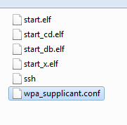
On my windows PC I have a "boot" drive shown when I insert the SD card:
When I open it, I show a bunch of files, similar to the following:

I right click, and choose "Create new text document", and then name a file "ssh". I then do the same, but named "wpa_supplicant.conf".
Once that's done, you can open wpa_supplicant.conf and edit it in Notepad++.
Attachments
No LCD Support, no buzzer, with screw connectors, and through-hole components.
Purchase Boards
Eagle Files:
Bill of Materials:
- TBD
1x 2-Pin 5mm Pitch Screw Terminal
1x 4-Pin 5mm Pitch Screw Terminal (Alternatively, 4x 2-pin terminals)
1x 10k 1/4 Watt Axial Resistor
1x RJ-11 Jack
1x WeMos D1 Mini ESP8266 board
LCD Support with DuPont connectors, and surface-mount level converter components.
LCD Support with DuPont connectors, through-hole components, and a SparkFun-based level converter sub-board.
LCD Support with screw connectors, through-hole components, and a SparkFun-based level converter sub-board.
Purchase Boards
Eagle Files:
Bill of Materials:
1x 2-Pin 5mm Pitch Screw Terminal
2x 4-Pin 5mm Pitch Screw Terminal (Alternatively, 4x 2-pin terminals)
1x 2-Pin Pin Header
1x 10k 1/4 Watt Axial Resistor
1x Sparkfun (or compatible) Level Shifter
1x RJ-11 Jack
1x WeMos D1 Mini ESP8266 board
1x LCD 20x4 I2C LCD Screen
I am useless when it comes to building circuit boards, so I have to ask, do the SMD boards come with the SMD components on them or do I have to figure out how to do that myself? Or just stick to the discrete components boards?
Bigdaddyale
Well-Known Member
No, You need to order all of the parts.this is just the files for the pcb.I have a run of SMD boards and parts on their way.
I am useless when it comes to building circuit boards, so I have to ask, do the SMD boards come with the SMD components on them or do I have to figure out how to do that myself? Or just stick to the discrete components boards?
Unfortunately, the SMD boards have to be hand soldered. That said - it's easier/more forgiving than it looks, but if you're worried about it I would stick to the discrete component boards. All the boards do the same thing - just in a slightly different package.
On a separate note, I have decided that I detest the strip-and-splice method for doing RJ-11 temperature sensors, so I'm going to be making a board shortly with a single RJ-11 jack (to connect to the PCBs linked) and 11 screw terminals ( 3x3 for the room/chamber/beer sensor, 1x2 for door). Completely optional, and a complement (not replacement) for the linked PCBs. Just a personal preference thing.
Bigdaddyale
Well-Known Member
That's how I spent my day, striping and soldering wire splices.I need to find a heat source that can shrink down the shrink tubing- the soldering iron made a mess of it.I ended up with a set of three probes, a 25 foot main wire that will plug in to the board and the probes will plug in to a 3 way phone splitter.On a separate note, I have decided that I detest the strip-and-splice method for doing RJ-11 temperature sensors, so I'm going to be making a board shortly with a single RJ-11 jack (to connect to the PCBs linked) and 11 screw terminals ( 3x3 for the room/chamber/beer sensor, 1x2 for door). Completely optional, and a complement (not replacement) for the linked PCBs. Just a personal preference thing.
Bigdaddyale
Well-Known Member
I gave up on the wifi for now and just plugged in an ethernet cable. Program loaded with out a hitch-Thanks Thorrak and team.I flashed my D1 Mini with the program from the github site posted above nodemcu -flasher. but I cant find it on the network. I'll play around with it later on tonight.On my windows PC I have a "boot" drive shown when I insert the SD card:
View attachment 393645
When I open it, I show a bunch of files, similar to the following:
View attachment 393649
I right click, and choose "Create new text document", and then name a file "ssh". I then do the same, but named "wpa_supplicant.conf".
Once that's done, you can open wpa_supplicant.conf and edit it in Notepad++.
Hmm ... now you need a small 3D printed enclosure for THAT.On a separate note, I have decided that I detest the strip-and-splice method for doing RJ-11 temperature sensors, so I'm going to be making a board shortly with a single RJ-11 jack (to connect to the PCBs linked) and 11 screw terminals ( 3x3 for the room/chamber/beer sensor, 1x2 for door). Completely optional, and a complement (not replacement) for the linked PCBs. Just a personal preference thing.
Good idea though.
Mikmonken
Well-Known Member
- Joined
- Mar 28, 2013
- Messages
- 423
- Reaction score
- 101
Three Fermentracks ticking along nicely added a new one each day for the last couple of days. The top controller has just been set to beer profile but it's holding temperature well. Would be nice to track on the graph when the heater and cooler trigger but I think that's in the pipeline.
So if anyone's on the fence based on my experience so far it's all working pretty well.
View attachment ImageUploadedByHome Brew1490301701.061313.jpg
So if anyone's on the fence based on my experience so far it's all working pretty well.
View attachment ImageUploadedByHome Brew1490301701.061313.jpg
stbernts
Well-Known Member
- Joined
- May 20, 2016
- Messages
- 257
- Reaction score
- 43
I`ve had some "Cannot receive Lcd TEXT.." - but those are more likely due to eiter power issues, or the fact that my Wifi could be a little bad from brew room to where Pi is. Will try to move Pi to the same room to sort out such problems. Esp8266 board runs and controls in background, so there seems to be some sort of timeout issue.
When pulling up the graph on my mobile devices, I only get a red box.
I tried dygraphs.com/css.html on my mobile devices and they pull up that instance of the graph fine.
I'm no front end developer, but after messing around with things it looks like is going on with the responsive updates to the div "panel panel-red" when you change window size horizontally.
I have no idea how to submit an issue in Github and do this the right way.
Mikmonken
Well-Known Member
- Joined
- Mar 28, 2013
- Messages
- 423
- Reaction score
- 101
When pulling up the graph on my mobile devices, I only get a red box.
I tried dygraphs.com/css.html on my mobile devices and they pull up that instance of the graph fine.
I'm no front end developer, but after messing around with things it looks like is going on with the responsive updates to the div "panel panel-red" when you change window size horizontally.
I have no idea how to submit an issue in Github and do this the right way.
That's interesting I did have this issue on iOS too then there was an update which seem to solve it, both landscape and portrait. Do you know if your on the most recent version? There should be a notification on the homepage if you can update.
On a separate note, I have decided that I detest the strip-and-splice method for doing RJ-11 temperature sensors, so I'm going to be making a board shortly with a single RJ-11 jack (to connect to the PCBs linked) and 11 screw terminals ( 3x3 for the room/chamber/beer sensor, 1x2 for door). Completely optional, and a complement (not replacement) for the linked PCBs. Just a personal preference thing.
For those who might be interested, I've gone ahead and created this. The PCBs.io link is https://PCBs.io/share/z7Rd1 . It's $9.38 for 4 boards there.
Basically the board is this:

I'll add the eagle files to the repo at some point in the near future.
stbernts
Well-Known Member
- Joined
- May 20, 2016
- Messages
- 257
- Reaction score
- 43
Anybody else who strugles if they reboot RaspberryPi? It wont connect to my esp8266 boards unless I cut power and put in on after Pi reboot.
Edit: Seems like the last version somehow fixed this. After upgrade the esp8266 showed up again.
Did a new reboot this morning of the pi - still gets the "Unable to reach brewpi-script for device Cola"
Is it supposed to be like that?
Edit: Seems like the last version somehow fixed this. After upgrade the esp8266 showed up again.
Did a new reboot this morning of the pi - still gets the "Unable to reach brewpi-script for device Cola"
Is it supposed to be like that?
rocket4x4
Active Member
- Joined
- Oct 1, 2013
- Messages
- 26
- Reaction score
- 8
Is there any way to enable a sub-site?
I have a tiltpi app - which I would love ro run as sub on the site.
Best reg,
Stig
What kind of app is it? Depending how it is run you only need to add an alias or you need to create a reverse proxy.
stbernts
Well-Known Member
- Joined
- May 20, 2016
- Messages
- 257
- Reaction score
- 43
This one: https://bitbucket.org/lgpaulsen/
PS. I`m not familiar with NginX, if someone could point me in the right directions - thanks in advanced.
It works - and shows nice graphs.
PS. I`m not familiar with NginX, if someone could point me in the right directions - thanks in advanced.
It works - and shows nice graphs.
rocket4x4
Active Member
- Joined
- Oct 1, 2013
- Messages
- 26
- Reaction score
- 8
This one: https://bitbucket.org/lgpaulsen/
PS. I`m not familiar with NginX, if someone could point me in the right directions - thanks in advanced.
It works - and shows nice graphs.
Sure, I would create a new nginx server in /etc/nginx/sites-enabled/tiltpi
and use nip.io for a hostname (maps ip to hostname) for example if
the raspberry pi has ip 192.168.1.2 then use "server_name tiltpi.192.168.1.2.nip.io;"
You also need to enable php which your can read about here:
https://www.raspberrypi.org/documentation/remote-access/web-server/nginx.md
Basiclly:
Code:
sudo apt-get install php5-fpmSomething like:
Code:
server {
        listen   80;
        # Where your tiltpi files are located
        root /var/www/tiltpi;
        index index.php index.html index.htm;

        server_name tiltpi.192.168.1.2.nip.io;

        location / {
                try_files $uri $uri/ /index.html;
        }

        # pass the PHP scripts to FastCGI
        location ~ \.php$ {
                include snippets/fastcgi-php.conf;
                fastcgi_pass unix:/var/run/php5-fpm.sock;
        }
}- Then access to tiltpi via: http://tiltpi.192.168.1.2.nip.io
- And Fermentrack will be default or for example: http://fermentrack.192.168.1.2.nip.io
darrenB996
New Member
- Joined
- Feb 5, 2017
- Messages
- 4
- Reaction score
- 0
Forgive me if this has been asked already, but how do I configure multi chamber.
I have a pi zero w and a d1 mini working. Do I need to add another d1 mini or have additional pin headers on the d1 mini beem programmed for an extra chamber heat and cool function.
Many thanks
I have a pi zero w and a d1 mini working. Do I need to add another d1 mini or have additional pin headers on the d1 mini beem programmed for an extra chamber heat and cool function.
Many thanks
Forgive me if this has been asked already, but how do I configure multi chamber.
I have a pi zero w and a d1 mini working. Do I need to add another d1 mini or have additional pin headers on the d1 mini beem programmed for an extra chamber heat and cool function.
Many thanks
You need to add additional D1 Minis & sensors - One set per chamber.
darrenB996
New Member
- Joined
- Feb 5, 2017
- Messages
- 4
- Reaction score
- 0
You need to add additional D1 Minis & sensors - One set per chamber.
Thanks Thorrak.
The pi zero w only has one usb port so I would also need to setup a powered hub to connect both d1 minis. Might just upgrade the zero to an rpi3.
stbernts
Well-Known Member
- Joined
- May 20, 2016
- Messages
- 257
- Reaction score
- 43
Sure, I would create a new nginx server in /etc/nginx/sites-enabled/tiltpi
and use nip.io for a hostname (maps ip to hostname) for example if
the raspberry pi has ip 192.168.1.2 then use "server_name tiltpi.192.168.1.2.nip.io;"
You also need to enable php which your can read about here:
https://www.raspberrypi.org/documentation/remote-access/web-server/nginx.md
Basiclly:
Code:sudo apt-get install php5-fpm
Something like:
Code:server { listen 80; # Where your tiltpi files are located root /var/www/tiltpi; index index.php index.html index.htm; server_name tiltpi.192.168.1.2.nip.io; location / { try_files $uri $uri/ /index.html; } # pass the PHP scripts to FastCGI location ~ \.php$ { include snippets/fastcgi-php.conf; fastcgi_pass unix:/var/run/php5-fpm.sock; } }
- Then access to tiltpi via: http://tiltpi.192.168.1.2.nip.io
- And Fermentrack will be default or for example: http://fermentrack.192.168.1.2.nip.io
Thanks for the effort, either I do something wrong or it did not work.
Lost fermentrack also, when I tried to use those "names"
This is the answer from nginx restart:
[....] Restarting nginx (via systemctl): nginx.serviceJob for nginx.service failed. See 'systemctl status nginx.service' and 'journalctl -xn' for details.
failed!
Similar threads
- Replies
- 10
- Views
- 2K
- Replies
- 3
- Views
- 2K
- Replies
- 7
- Views
- 2K
