Moving to BREW IN A BASKET

Homebrew Talk - Beer, Wine, Mead, & Cider Brewing Discussion Forum

Help Support Homebrew Talk - Beer, Wine, Mead, & Cider Brewing Discussion Forum:

This site may earn a commission from merchant affiliate links, including eBay, Amazon, and others.
Am I understanding this correctly? You feel that a perculator will make better coffee than a french press?
Its been a while since I used my french press but it works more effectively because of high heat and the actual physical squeezing, thats my point you dont see a version where you just pour the hot water in and then drain without either agitating the coffee or water to extract more from the grain. coffee makers work with constant liquid flowing through the coffee bed perculators recirculate the water through and the longer you let them go the stronger the coffee. french pressses require the boil to agitate everything as well as pressing.
 
Thanks Blizz81. Sorry I am not sure I understand what you mean by your first statement about keeping volume left in keg to a minimum. So I'm assuming the modified keg has an ID like mine of 15.5 inches, so your basket must have an OD of about 14.5 inches. Correct? You don't have any couplings, etc. that protrude into the interior of the keg, correct? What is the height of the basket? How high are the feet on the basket? What did you make the lid from? Thanks and sorry for all the questions.


To clarify regarding bottom-draining, generally the nature of setups that drain using a diptube + a spigot will leave some wort behind. I wanted my setup to be able to maximize wort retrieval, and thankfully Bobby @ Brewhardware had a nice little kit to take advantage of the normal keg top opening in that way.

No fittings on the keg that protrude inside, correct. My basket is 15" OD by 17" tall as I wanted the top rim + handle to sit just above where I had cut the keg so I didn't need room for the swing handle inside the keg. I didn't get feet as I planned to have it just sit on top of the false bottom I had previously been using, but my false bottom is a little under 15" and in reality the basket set itself on the curvature of the keg wall to where it was hovering just above the false bottom.

So I repurposed the false bottom as the lid, since I figured I already had a hinged stainless piece almost the correct diameter. I had a weldless bulkhead + locline sitting around so I used that on the lid - it sweats a bit in this application around the base, but not detrimental to operation.

With the false bottom previously in use, I had been used to there being I think a little less than a gallon of volume under the false bottom (saved in my calcs, I forget the #), so that pretty much stayed the same for my mash calculations. I'm not sure if it would be possible to fit elements in that space since the keg wall is curved at that point - might be that the lowest point you could mount elements would give you a bit more volume under the basket.
 

Attachments

  • image1.jpeg
    image1.jpeg
    2.5 MB · Views: 117
  • image2.jpeg
    image2.jpeg
    1.5 MB · Views: 115
Last edited:
To clarify regarding bottom-draining, generally the nature of setups that drain using a diptube + a spigot will leave some wort behind. I wanted my setup to be able to maximize wort retrieval, and thankfully Bobby @ Brewhardware had a nice little kit to take advantage of the normal keg top opening in that way.

No fittings on the keg that protrude inside, correct. My basket is 15" OD by 17" tall as I wanted the top rim + handle to sit just above where I had cut the keg so I didn't need room for the swing handle inside the keg. I didn't get feet as I planned to have it just sit on top of the false bottom I had previously been using, but my false bottom is a little under 15" and in reality the basket set itself on the curvature of the keg wall to where it was hovering just above the false bottom.

So I repurposed the false bottom as the lid, since I figured I already had a hinged stainless piece almost the correct diameter. I had a weldless bulkhead + locline sitting around so I used that on the lid - it sweats a bit in this application around the base, but not detrimental to operation.

With the false bottom previously in use, I had been used to there being I think a little less than a gallon of volume under the false bottom (saved in my calcs, I forget the #), so that pretty much stayed the same for my mash calculations. I'm not sure if it would be possible to fit elements in that space since the keg wall is curved at that point - might be that the lowest point you could mount elements would give you a bit more volume under the basket.
Thanks a ton Blizz for the details, very helpful to me. In a worst case scenario, when you do high-gravity (lets say a 12 pound grain bill), 5 gallon brews, approximately where is the mash/liquid level in your basket? In other words how far from the top of the kettle is the mash/liquid? I'm curious how full the basket is, worst case scenario, because I want my basket to be a few inches below the return for recirculation as shown in the attached. If you don't know exactly that is OK, but approximately where is that mash level? My basket top needs to be just below the return coupler. Thanks, Mike123.
 

Attachments

  • BIABasket Recirculation.jpg
    1.3 MB · Views: 67
12 pounds is not "high-gravity"...20+ pounds is.

I think I had something like 25# in my 15 gal kettle once. It was pretty close to the top of the kettle with BIAB mash in water and all the grain.

Your keggle is 15.5 gal I think so you will be there too on a monster grain bill.
 
Thanks a ton Blizz for the details, very helpful to me. In a worst case scenario, when you do high-gravity (lets say a 12 pound grain bill), 5 gallon brews, approximately where is the mash/liquid level in your basket? In other words how far from the top of the kettle is the mash/liquid? I'm curious how full the basket is, worst case scenario, because I want my basket to be a few inches below the return for recirculation as shown in the attached. If you don't know exactly that is OK, but approximately where is that mash level? My basket top needs to be just below the return coupler. Thanks, Mike123.
Mash volume is approximately:
Mash Volume = Strike Volume + 0.08 gal/lb * Grain Weight
Brew on :mug:
 
Mash volume is approximately:Mash Volume = Strike Volume + 0.08 gal/lb * Grain Weight


^ That'd probably be a better way to estimate for your system. I still batch sparge and drain runnings to a separate boil kettle, so I don't have a full-volume mash (I run a 1.25qt/lb ratio), so a 12lb grain bill ends up pretty low in the keggle for me. Doing a 24lb grain bill for a 5gal batch tomorrow, will be thankful for the return bulkhead through the lid on that batch :)
 
OK I'm considering modifying my keggle, cutting off the top at the seam so I can fit a 14" diameter grain basket into it (I am limited by some couplers in the side walls), and the basket will be 15 inches high...a 10 gallon max capacity grain basket. Assuming a single vessel brew-in-a-basket (5 gallon yield). (3 inches dead space below the basket) Also assuming a 12 pound grain bill, the result is a 10 gallon mash volume using the equation doug provided, using 3 quarts of water per pound of grain which I've read is typical for brew in a bag, essentially what I am doing except with a basket. If all this is correct I won't be brewing any 5 gallon beers requiring more than 12 pounds of grain, it just won't fit in the basket. Since I would have a 3 inch dead space below the basket, I'm approximating 2 gallons liquid won't reside in the grain basket, which will affect the efficiency I suppose due to a slightly thicker mash. I plan to recirculate, so far using the vertical return pipe shown in the sketch, to improve efficiency. Comments welcome. You guys that have done this have any suggestions? Is my 3 quarts of water per pound of grain a bad number? I could always brew smaller batches of beer for recipes with a mash volume exceeding my grain basket capacity.
 

Attachments

  • BIABasket Recirculation.jpg
    2 MB · Views: 81
Last edited:
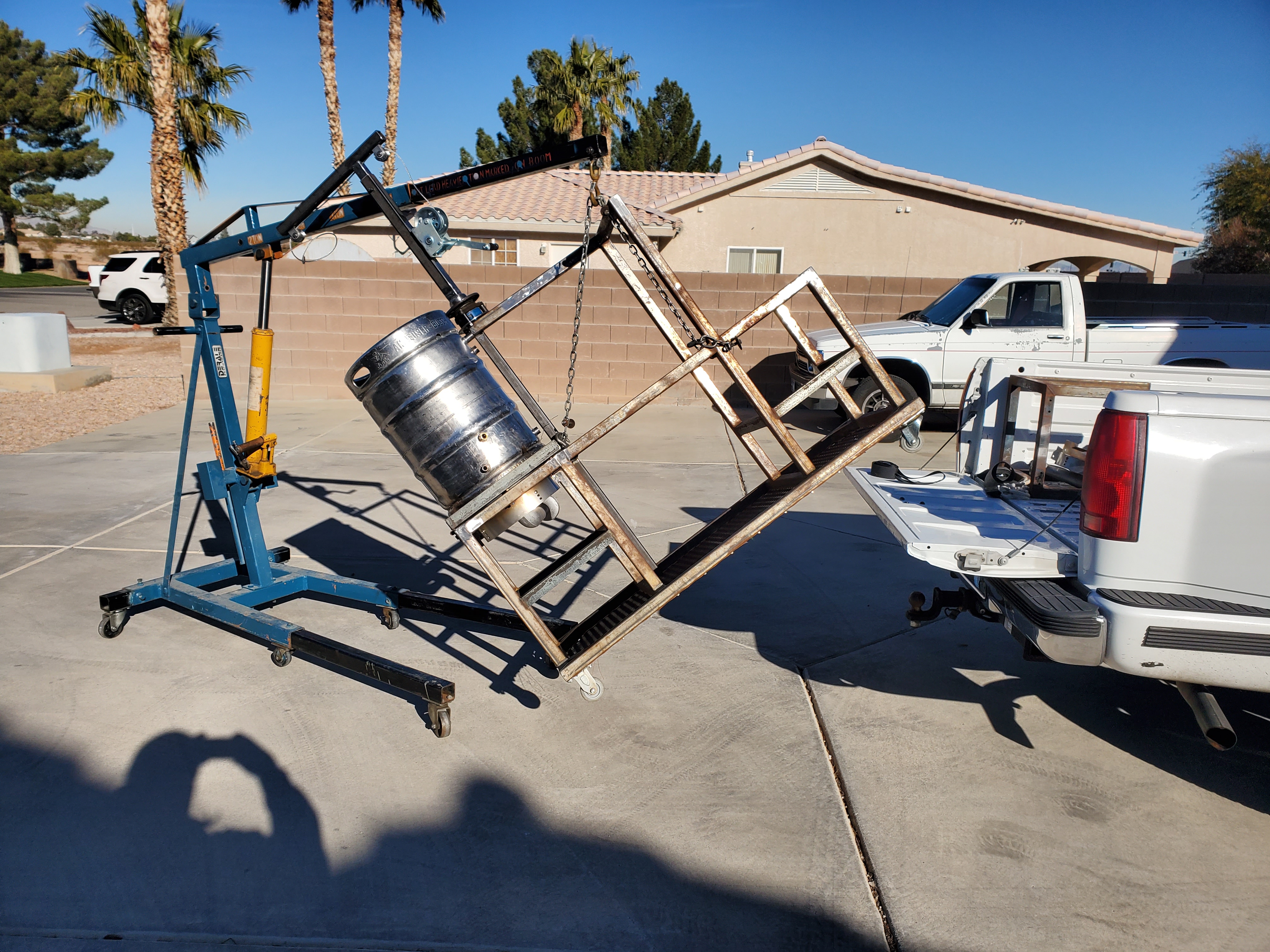
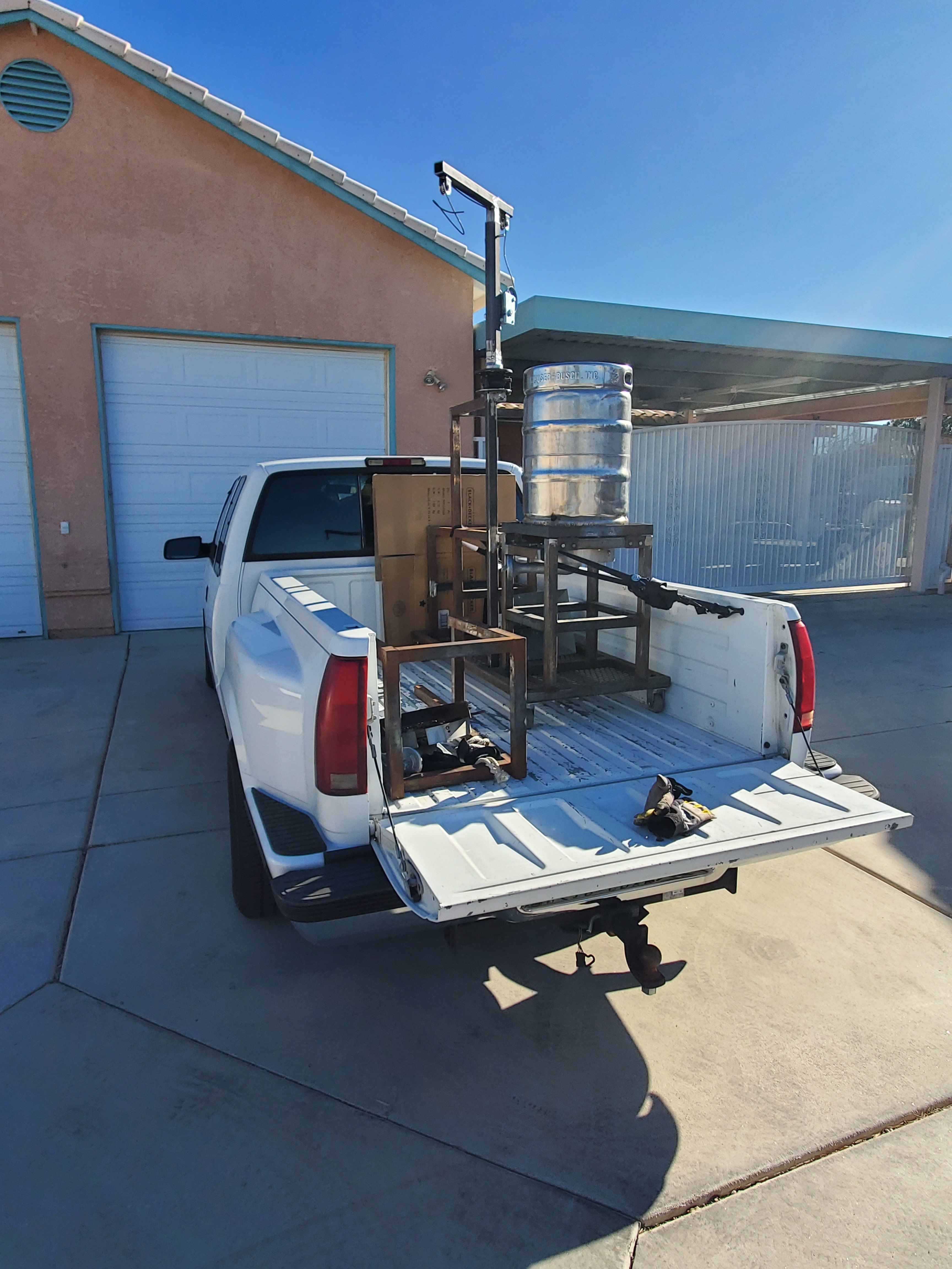
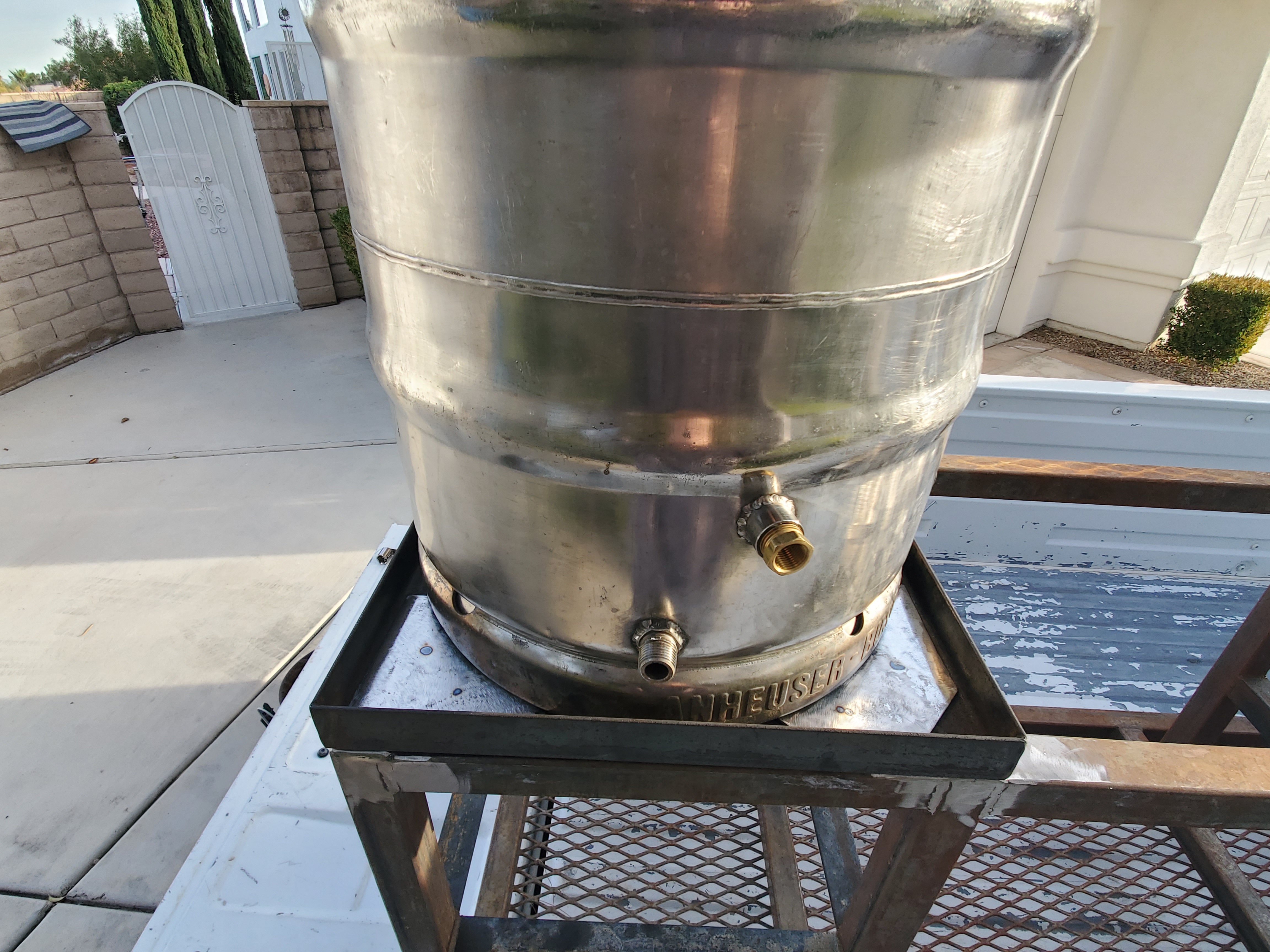
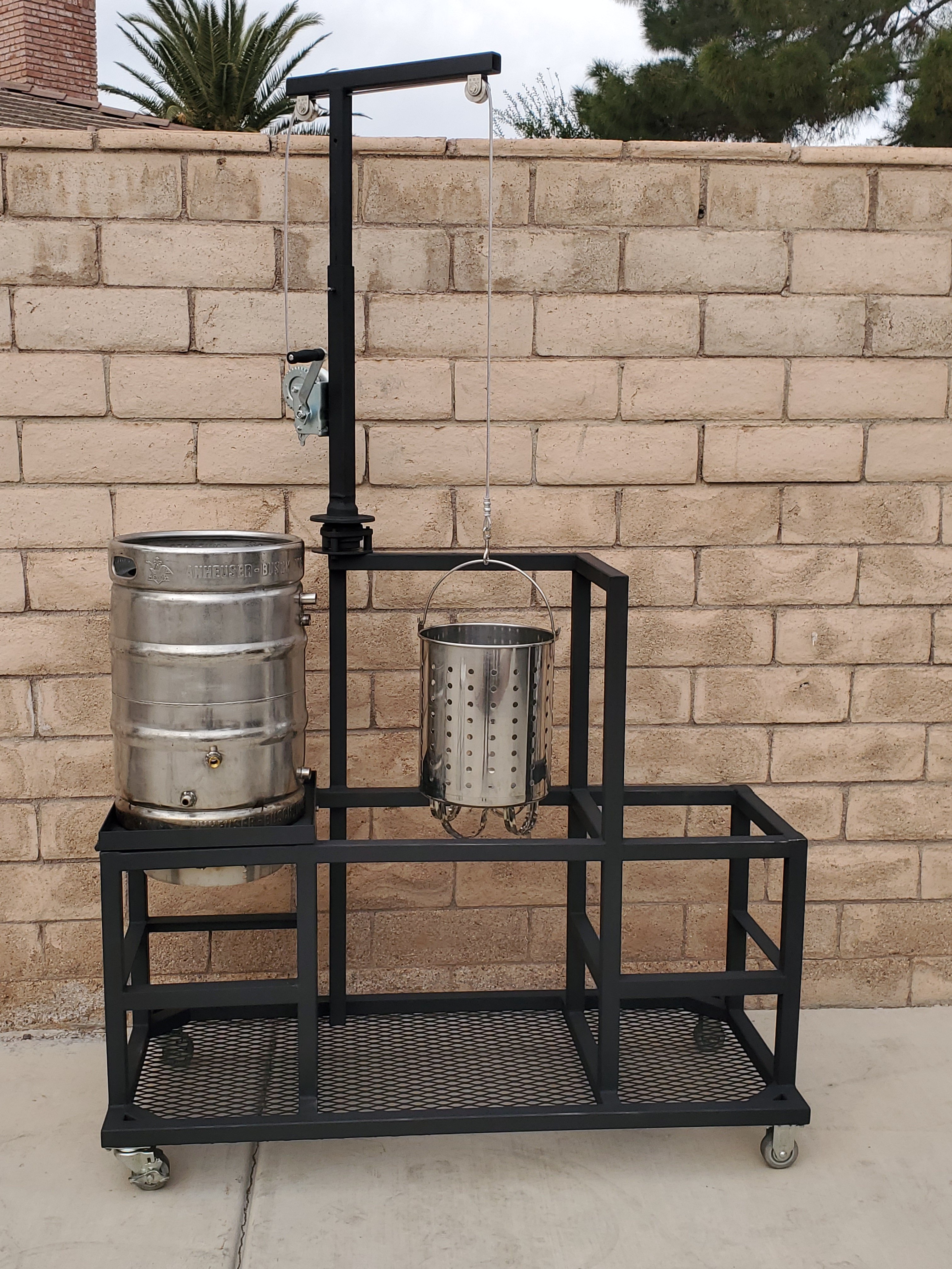
OK as I said I am continuing with my redesign and modifications of my original 3 vessel rig to a single vessel one. Here is my progress with the frame and burner mods, and the addition of a hoist. Here are some descriptions of the images. Sorry about possible duplicate pics, and the order is random.
I loaded my reassembled brew rig into my truck to take it home and finish (rust busting, painting, reassembly.) Next you can see I added some plates above the burner, in the front, to block the heat that has been an issue. My design vents heat primarily to the rear. Worked good, should work better now. At home I disassembled the rig, spent several hours removing rust, and next I will paint the frame. Then I'll reassemble everything and move on to details of my keggle, grain basket, and recirculation as related to the keggle. More pics as I progress, assuming there is interest.
20191217_095404.jpg
20191217_101414.jpg
20191217_151352.jpg
20191217_151301.jpg
20191217_151412.jpg
20191217_153444.jpg
20191219_132358.jpg
 
Last edited:
Looks like a work of art
Gee thanks Odie, I appreciate that. They do call these Beer Sculptures, right? I have this thing about my rig looking good, to a fault I suppose because it is an obstacle sometimes to just doing what will make it work. For example I refuse to cut the top of the keg off, so far anyway. I'm getting a lot of advice that is functionally good stuff, but in many cases would not look good. Down the road if I can't make good beer I can buy good beer and sit and look at my art. Haha. I know I have a problem. We will see...…..damn the torpedo's, full speed ahead.
 
German vs Italian cars....they are both marvels of ingenuity and performance...German stuff "must work"....Italian stuff must look good while working, but it still "must work"...and they both require maint and care...they are after all, not your father's Buick.
 
German vs Italian cars....they are both marvels of ingenuity and performance...German stuff "must work"....Italian stuff must look good while working, but it still "must work"...and they both require maint and care...they are after all, not your father's Buick.
Odie - Speaking of vehicle beauty and functionality, I get that totally. In fact I have a project truck that took me 6 years (and counting) to get right. And it works great too! I'm thinking about painting my brew rig red to match my truck, what do you think? Versus low gloss black, which is my current choice.
Goodsprings Test Drive.jpg
 
that is sweet...please tell me it has a wooden bed...

paint it to match if you are gonna use it to go to brew club gathering and such...
 
that is sweet...please tell me it has a wooden bed...

paint it to match if you are gonna use it to go to brew club gathering and such...
Sorry, no wooden bed. Here in Las Vegas the sun and heat is brutal and I did not think a wood bed would last. However, the bed has a Rhino coat that matches the truck paint. Looks good (and it works haha).

I could not find the high heat (2000F) paint that I chose in a red color. Only available in flat black so that will be the brew rig frame color. That is OK, it won't show soot and discoloration so easily that way. Going to start painting today.
 
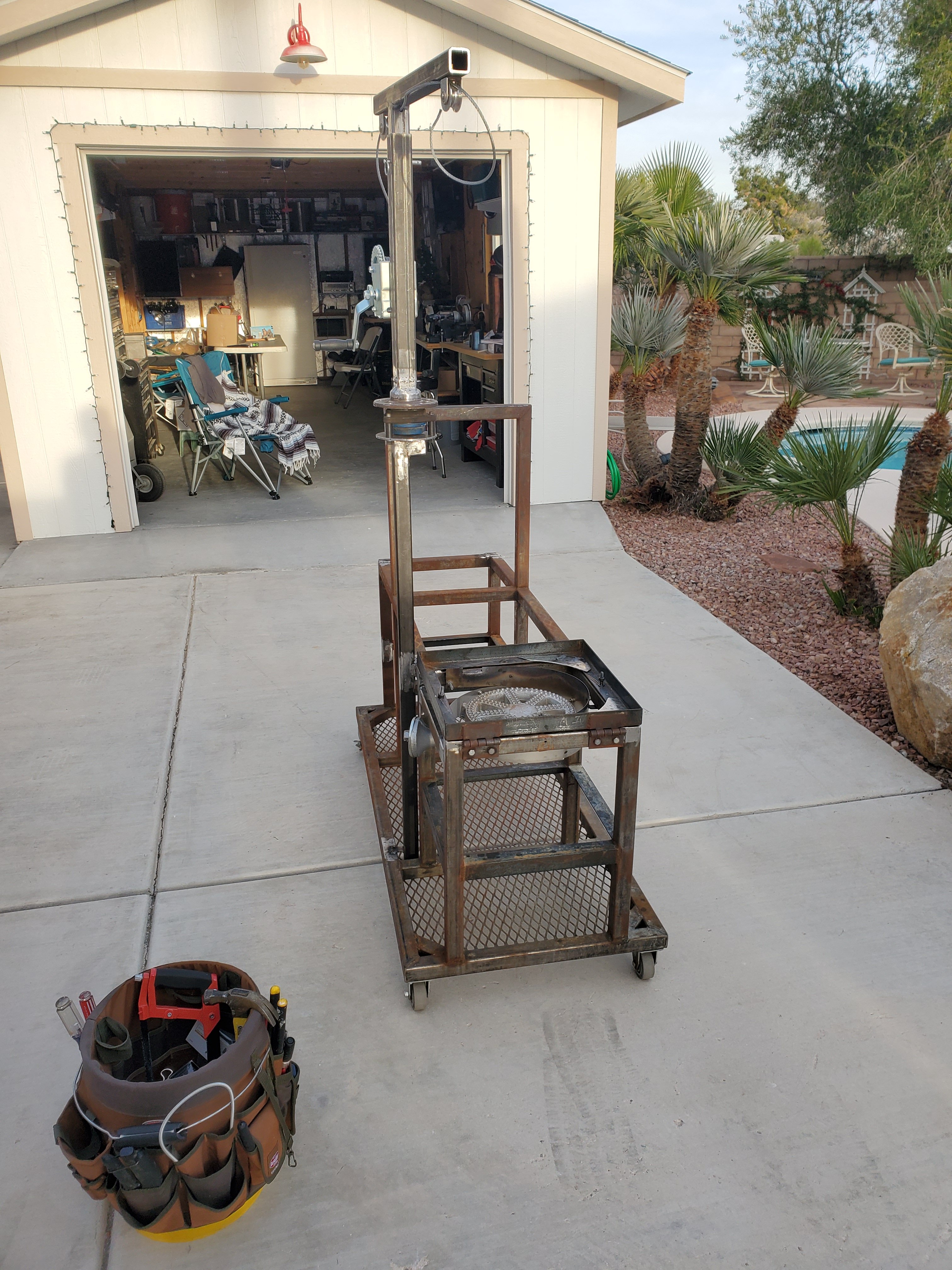
The frame is painted. Flat black. Not a lot of options in the high heat paint I used. Now on to reassembly and mounting components. It is upside down in this picture.
20191221_152132.jpg
 
This is the basic painted frame with the hoist/yardarm and winch installed. I found a dog tie cable with swivel hook to use for the cable, versus buying the parts and making one. Next I have to make, install, and paint another upper level expanded metal work surface. Then mount the pump, chiller, and other components. Not bad so far, all according to plan. Still scratching my head on the final keg/grain basket configuration. I'm pretty sure I'm going to order a custom grain basket when I know for sure what size it will be. I'm in the process of figuring out how to optimize the basket size, without modifying the keg any further.
20191222_122112.jpg
20191222_122245.jpg
 
Glorious work!

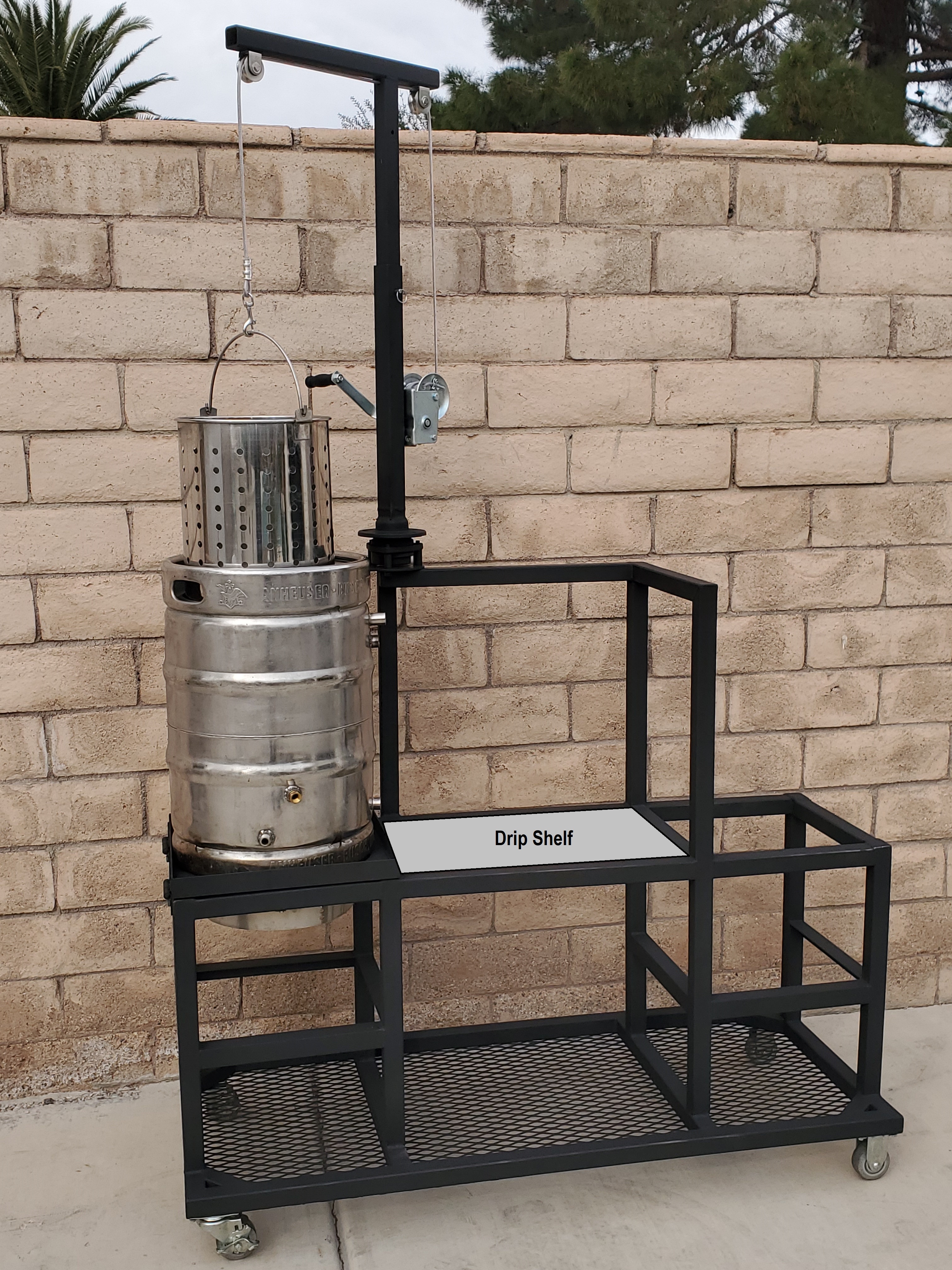
You might want to think about how you are going to catch the drippings of the basket. It will drip for many minutes after you pull it from the pot. Some kind of drip pan might do the trick. A cookie sheet maybe?
 
Just leave it suspended over the kettle while it drips

In my experience it pretty much never stops dripping! lol

I was just looking at that basket hanging over the expanded metal. It would be smart to have some kind of a drip pan so it doesn't drip over that metal which would be tough to clean.
 
Mine hangs over the kettle almost the entire boil. I have a bag in a steamer basket for mashing. I pull the basket and stick a couple very long screwdrivers under the basket and drop it on the kettle rim. Then I hoist the bag out of the basket and move the basket aside. The bag alone will drain pretty quick and can be squeezed too.
 
Yes dripping is a concern. I have considered the dripping problem but not experienced it yet. I plan to somehow "squeeze" the grain with the basket suspended over the keggle, possibly with a round/flat pot lid, to get most of the liquid out. Then I was going to leave the basket suspended above the keggle to continue dripping as I bring the wort up to a boil for hop additions, etc. That should take a while, 15 to 20 minutes maybe? If it continues to drip after that I'll have something under it as I swing it away from the keggle.

This gives me an idea actually. I have not yet made the expanded metal shelf to be located to the right of the keggle. Perhaps I should, instead of expanded metal, make that surface a solid one with a lip around (like a large rectangular pizza pan) it so any spillage would be caught. Either way I have to put out some money. I also plan to mill the grain in that same location, so that solid shelf would catch the inevitable spillover milled grain versus falling through an expanded metal shelf onto components mounted below (pump, chiller, valves, etc). I'll need a little luck finding a pan that fits exactly, but for grins I found this 16"x18"/18 gauge one online for $5.....maybe I can find a similar one to fit at the restaurant supply house, or a good will store. I might need to reinforce underneath depending on the pan thickness. I might even do the same for the work surface to the far right of the rig. Thanks for the ideas. That is why I post here.

Drip Pan Shelf.jpg
thgalsp1622.jpg
 
Does anyone know of a stainless steel coupler (1/2" Elbow, NPT Female to Male) that is smaller in length, in the 1.5" dimension, of this one? I need one that is half that length, if possible.
Elbow.jpg
 
Not really possible if its going to have full bore
Yes Bobby M, I have to agree. I'll have to find another way. I considered cutting off part of the nipple mounted in the keg wall, but since it is tapered that won't work either.

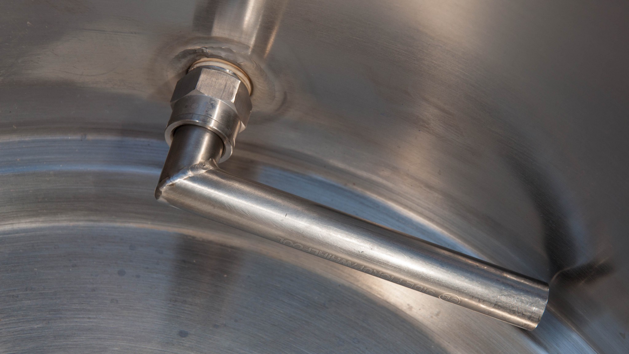
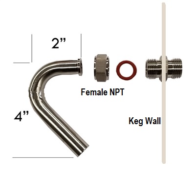
Another possibility is a product like the ones shown in the attached images. I believe it has a 1/2" Female NPT connector, and the welded 90 degree results in what appears to be a short protrusion into the kettle. I've also seen these made with a tube 90 that has been "bent", versus welded like. The tube pushes into the connector by hand, no tools required, so I'm sure there is an o ring seal, as shown in one of these pics. I am not sure this seal would hold up to the high heat in my direct fired propane kettle setup......I think these are intended for electric heating. I would buy it with a tube that is much longer, and bend it myself to hug my keg inner walls and bottom, and the part that pushes into the connector could be shortened also I believe. The company that sells this shows pics of the bent version and this welded version. I'm not sure which is available for purchase......sent them an email. I need to know the dimensions of this item.
11_SpikeKettleReview_SidePickUpConnected.jpg
brewhardware Diptube_Edge-4T.jpg
 
Last edited:
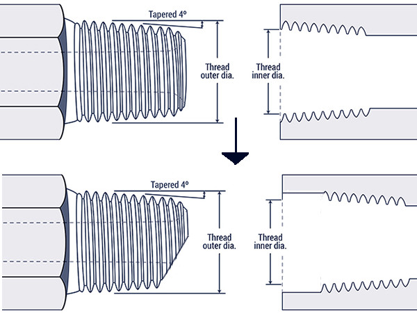
Go bug a plumber or gas installer, some have the thread cutting dies to cut 1/2" NPT threads as part of their normal tools. Then you can cut the nipple and rethread to restore the taper.
Thanks Bruce. I thought about this approach........I have a friend with dies and we talked about doing just that. Cut the nipple and rethread. He explained that since the nipple is tapered along it's length, this is not possible. The die stops and won't rethread the full length of the cut nipple. I'll look into this further.
 
Thanks Bruce. I thought about this approach........I have a friend with dies and we talked about doing just that. Cut the nipple and rethread. He explained that since the nipple is tapered along it's length, this is not possible. The die stops and won't rethread the full length of the cut nipple. I'll look into this further.

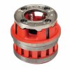
As far as I am aware, a NPT die can cut a flat pipe into the proper taper starting from the maximum diameter of the taper, it doesn't need the taper to be machined in first. The plumbers I've seen doing this have the industrial style dies, like the one below, that are effectively much deeper than the single piece dies and cut the entire thread length.

RIDGID_36875.jpg
Another solution might be to ream out the female side of the elbow and then cut a new thread deeper into the elbow allowing it to thread further up the nipple. The nipple will partially block the bore on the male side, but you can easily trim the face of the nipple at an angle to open up the bore again. There should be sufficient metal to cut the thread so the end of the nipple protrudes halfway into the opposite bore.

alternate example.jpg
 
As far as I am aware, a NPT die can cut a flat pipe into the proper taper starting from the maximum diameter of the taper, it doesn't need the taper to be machined in first. The plumbers I've seen doing this have the industrial style dies, like the one below, that are effectively much deeper than the single piece dies and cut the entire thread length.

View attachment 658899
Another solution might be to ream out the female side of the elbow and then cut a new thread deeper into the elbow allowing it to thread further up the nipple. The nipple will partially block the bore on the male side, but you can easily trim the face of the nipple at an angle to open up the bore again. There should be sufficient metal to cut the thread so the end of the nipple protrudes halfway into the opposite bore.

View attachment 658900
No amount of rethread is going to shave .75 inches. What is the purpose? Alternative ideas may spawn out of necesity rather than direct specification.
 
No amount of rethread is going to shave .75 inches. What is the purpose? Alternative ideas may spawn out of necesity rather than direct specification.

Thanks Bruce, I will definitely talk to my friend that has dies to see if we can do that. One problem is the location of the connectors, inside the bottom of the Keggle. Not sure we can cut off the connector, or turn the die in that confined space, but will see what we can do.

Bobby, the best way to answer your question about what is the purpose is...….....referencing this picture, I need to run a dip tube (stainless steel or copper) from the male NPT connector down along the Keggle wall contour to the center of the keggle bottom, without adding any more than 1/2 inch to the current horizontal protrusion into the Keggle caused by the NPT connector. The 90 and whatever else that connects to the NPT connector can't add any more than an additional 1/2" to the male connector. The dip tube will be 1/2" OD and hug the Keggle wall and bottom of the Keggle. All this is so that I can fit the largest possible grain basket into my keggle, which would be approximately 12.125" OD. I know I'm asking a lot.

I don't want to change the Keggle to another vessel, or change the basket diameter or shape, I'm looking for a way to get the dip tube hardware to not to be an obstruction. I may end up making or modifying something similar to Bruce's suggestion.

Finally......the dip tube could be connected to the female 1/2" NPT on the Keggle wall (a thermometer port), which would relax the requirement a little because it protrudes a little less than the male NPT connector.

Also, if there was a way to bring a 1/2" tube through the female NPT and do a hard 90 that might work, but I don't know how to seal it except possibly welding it to the NPT on the outside of the Keggle (weld the outside of the tube to the female NPT on the outside of the Keggle)....I only have access to a MIG welder so it would rust, but since it would be on the outside that would be OK.

Gee I hope this makes sense. I truly appreciate you guys making suggestions. Thanks. This one is stumping me.

20191224_133158.jpg
 
Lemme toss a couple of wild-ass ideas around. I am assuming from your drawing that the 1/2" limit is from the current end of the nipple.

One, if that is a 1/2" internal diameter nipple, then you should be able to slide a 1/2" outside diameter SS or copper tube through it with a snug fit or run a drill through it to ream it out if too small. If that is the case and this is a hot-side keggle, then capillary solder the joint between the tube and the nipple with a silver solder. Cut the nipple back as far as you can to minimize the intrusion inside the keggle and use a capillary elbow on the stub of 1/2" tube coming through the nipple to turn it downward. A 1/2" ID elbow is about 1" on the long axis, so depending how far back you can cut the nipple, it should cover your requirement.

Two, similar to one, but if you use 1/2" SS tube, you can MIG-weld with a stainless steel feed wire and not get rusting. Detailed discussion here if you want, https://forum.millerwelds.com/forum/welding-discussions/13661-can-i-mig-weld-stainless-steel

Three, pull the nipple completely, put a 1/2" female thru-wall weldless bulkhead in and use a male to male elbow.

thruwall-bulkhead.jpg


Four, same as three, but use a welded bulkhead instead and bias it to the outside to minimize the inside intrusion.

wildideas.jpg
 
Lemme toss a couple of wild-ass ideas around. I am assuming from your drawing that the 1/2" limit is from the current end of the nipple.

One, if that is a 1/2" internal diameter nipple, then you should be able to slide a 1/2" outside diameter SS or copper tube through it with a snug fit or run a drill through it to ream it out if too small. If that is the case and this is a hot-side keggle, then capillary solder the joint between the tube and the nipple with a silver solder. Cut the nipple back as far as you can to minimize the intrusion inside the keggle and use a capillary elbow on the stub of 1/2" tube coming through the nipple to turn it downward. A 1/2" ID elbow is about 1" on the long axis, so depending how far back you can cut the nipple, it should cover your requirement.

Two, similar to one, but if you use 1/2" SS tube, you can MIG-weld with a stainless steel feed wire and not get rusting. Detailed discussion here if you want, https://forum.millerwelds.com/forum/welding-discussions/13661-can-i-mig-weld-stainless-steel

Three, pull the nipple completely, put a 1/2" female thru-wall weldless bulkhead in and use a male to male elbow.

View attachment 659050

Four, same as three, but use a welded bulkhead instead and bias it to the outside to minimize the inside intrusion.

View attachment 659051
Thanks much Bruce. I have considered your idea of "…..slide a 1/2" outside diameter SS or copper tube through it with a snug fit or run a drill through it to ream it out if too small. If that is the case....", and I may still do that. The SS tubing I have won't quite fit but as you say reaming it out a bit would do the trick, and silver soldering would work to seal it off.

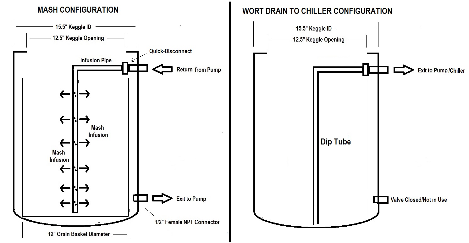
I woke up at 3AM with another idea that might work, what do you guys think? (I'm recently retired so that happens a lot). What if I don't put the dip tube at the bottom of the Keggle? What if I add a longer dip tube when I need it, at the end of the boil, using the return connector I've mentioned before located at the top of the Keggle? Please look at the two images. Referencing the return "infusion pipe" for the mashing process, which is a quick-disconnect/copper pipe as illustrated below...…..when I am done with the mash I'll of course remove the return "infusion" pipe, and the grain basket, and then after the boil I can reattach (via the same "quick-connector") another copper pipe without holes and use it as a dip tube. It will extend to the bottom of the Keggle of course. This way I don't have to fuss with anything at the bottom of the Keggle. I can make the basket extend all the way to the bottom of the Keggle, maximizing it's volume. This introduces a new issue, how to prime the pump and longer/higher dip tube combination. Perhaps prime using the bottom connector and switch over to the dip tube during pumping??
mash rtn infusion pipe.jpg
Infusion Pipe and Dip Tube.jpg
 
Last edited:
That would be the simplest solution. You can rig it that the prime remains from the recirculation stage, but you'll need a couple of valves.

If you want a permanent mounting solution for the pump and hoses, you can build it with three 3-way L port ball valves. I can sketch you a diagram if you want, just on the tablet now with no sketching software.

You can also rig something changeable with simple shutoff valves on the 1/2" exit and return nipples as well as on the intake and outlet of the pump with QD fittings on the dry side and then switch hoses around.

With a QD on the outside of the keggle, you can also build a CIP arm to clip onto the inside QD and then hook the garden/sink hose to the outside one to spray the keggle out.
 
All great ideas Bruce, and thanks to you and everyone who has responded. I appreciate it.

I'll try to do something now instead of "paralysis by analysis", and let you know how it goes. Hahaha.

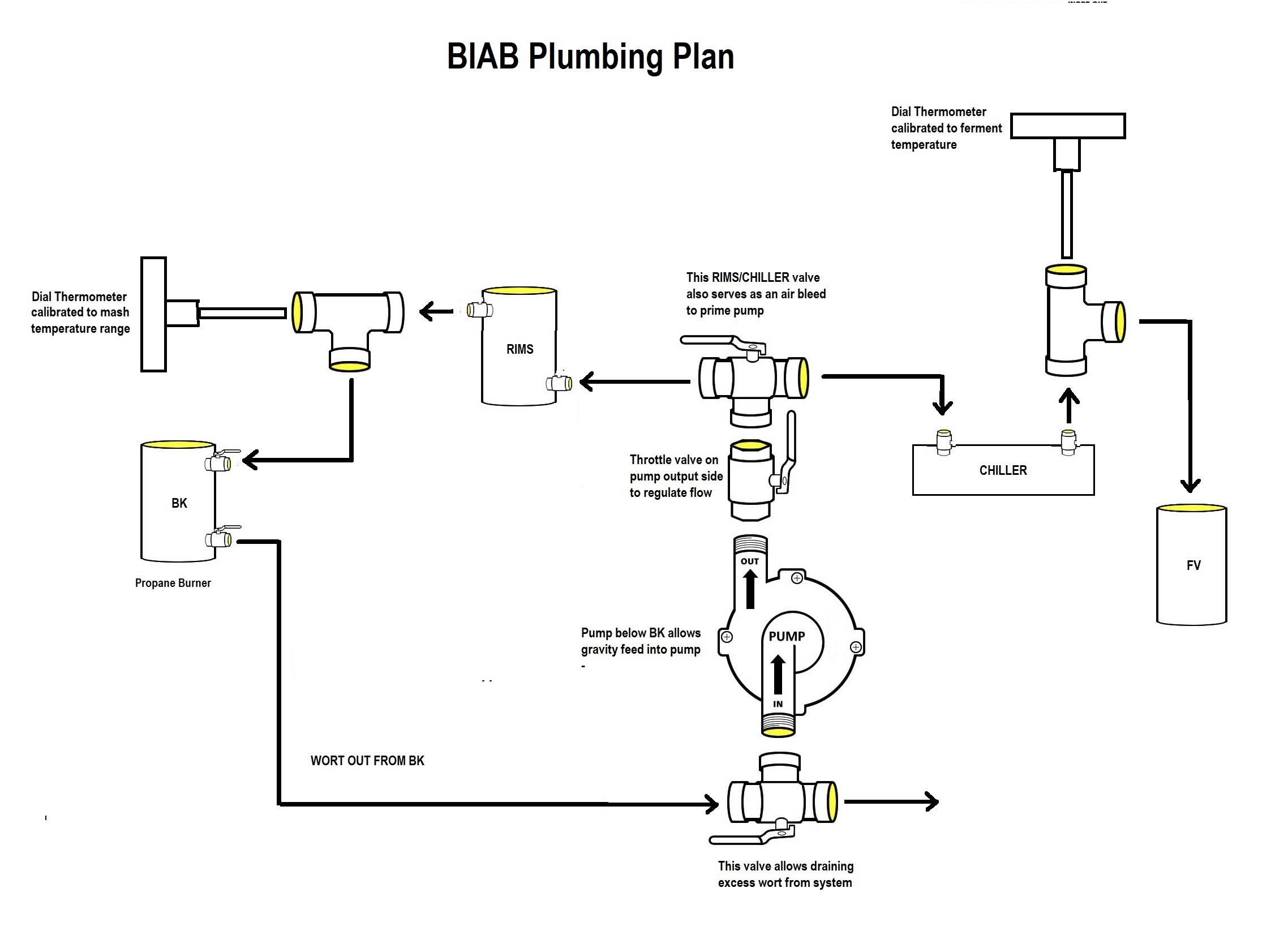
Yes Bruce, or anyone with ideas, if you want to give me plumbing ideas regarding priming, or anything else . Here is my original plumbing plan. I think I only need to add something for priming the new dip tube approach. Anything you want to throw out I'm catching. Thanks, and Happy Holidays.
BIAB Plumbing Plan.jpg
 
Here you go, three by three way L ports. On the diagram In is the common port on the three way, with A and B being the selectable ports. So valve position 1 connects In to A and position 2 connects In to B. In is inverted on V2 as the output.

V1 is the mash/drain selector.
V2 is the pump intake selector.
V3 is the pump output selector.

If I've got my logic right, with all valves in the A position, the flow should be from the top port, now fitted with the dip tube, through V1 and V2 into the pump and then out to the chiller via V3. With all valves in the B position, the flow will be from the bottom port, through V2 into the pump and out via V3 into the RIMS and then through V1 back into the BK via the infusion tube.

You can vent air to prime either via the A position on V3 if the chiller isn't connected, or via the B position on V1 and V3 back through the top port.

Three-way plumbing.jpg
 
Here you go, three by three way L ports. On the diagram In is the common port on the three way, with A and B being the selectable ports. So valve position 1 connects In to A and position 2 connects In to B. In is inverted on V2 as the output.

V1 is the mash/drain selector.
V2 is the pump intake selector.
V3 is the pump output selector.

If I've got my logic right, with all valves in the A position, the flow should be from the top port, now fitted with the dip tube, through V1 and V2 into the pump and then out to the chiller via V3. With all valves in the B position, the flow will be from the bottom port, through V2 into the pump and out via V3 into the RIMS and then through V1 back into the BK via the infusion tube.

You can vent air to prime either via the A position on V3 if the chiller isn't connected, or via the B position on V1 and V3 back through the top port.

View attachment 659258
OK I have to go make a dip tube and infusion pipe next, and do some dry (wet) runs of the plumbing system. BEFORE I commit and buy a custom grain basket.

Meanwhile I have a couple of questions.....possibly repetitive but I'm still looking for ideas;

1. Anyone with experience with the Blichmann Hop Rocket in a RIMS application, please tell me how well it has worked and what technology (PID, SCR, etc) you use to control the temperature. I think I would rather buy a control unit versus building. I have no control unit of any kind so far. That will be a last step in this process. Initially I only plan to use the Hop Rocket to control temperature during the mash, without hops in it, etc.

2. Now that I have a solution to the dip tube interference with the grain basket, the basket can sit directly on the Keggle concave bottom. I have a direct fired propane setup. Do I need any space between the bottom of the grain basket and the Keggle bottom? It will only make contact in a "circle" on the Keggle bottom due to the concave shape of the Keggle bottom. Can the basket simply rest directly on the bottom, or will that risk scorching the grain?

Thanks,
Mike

Thanks,
Mike
 
If you fire the burner while the grain is in the basket you would certainly risk scorching. Of course, it depends on how hot you fire, etc. In my early BIAB days I did some direct firing. I found that the grain really insulated the wort from the heat. It would get very stratified very fast.

If you are planning to create a RIMS setup, you shouldn't need to fire the burner to control temp. Maybe you are thinking for temperature changes?

This isn't really my wheelhouse, but I would suggest some feet on the basket to get a little circulation below the basket. I would also suggest you figure out how to recirc around the basket if you are going to direct fire so that you can help the wort circulate better as you heat it.
Thanks Neo, good points. I will need the burner only initially, before I get a RIMS temperature controller, to keep mash temperature constant. I will only be adding heat minimally to keep the mash temperature constant, but I think it is prudent to have some feet on the basket, at least 1/2 inch. Since the basket bottom is flat, and the Keggle bottom is concave, the intersection is a circle.....so there is a gap (I'm approximating 1 inch) below the basket. However it is somewhat trapped in that area. I may put 1/2" feet on the basket.
 
Back
Top