
silverbrewer
Well-Known Member
Here is a set of pictures detailing my build of this mammoth cooler. It fits in my 22 Imperial gallon brewpot. I have more pictures of the making of the former, but I am only able to post ten pictures. perhaps I can creep more in later.

Here is the assembled cooling coil array. It has six separate coils giving a total of 96 ft of 1/2" copper pipe. When connected to the mains water supply it flows 15 litres per minute which is about 4 US gallons. The water supply is provided via a six way manifold, so each coil get it's own supply, then the hot water exits via another manifold to be saved for washing duties later. Even when held at an angle like this, the coils do not touch each other! You can even shake it without any rattles!
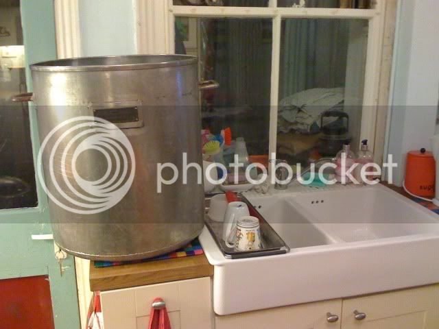
This is just to give you an idea what 22 imperial gallons looks like!

The former with a finished coil The blue tape is the guide to get the spiral correctly spaced.

A 5 meter length of pipe is filled with dry sand, This is tamped down firmly and then the pipe is capped. I did this by standing on top of my garage so I could reach 5 meters high (over 16 ft) and I then filled the pipe with dry sand through a small funnel! The pipe is then laid out straight somewhere soft (the lawn) and is inserted down the formers central hole. It is then formed around the end of the former either left or right and then wound around the formers outer surface following the spiral guide tape (blue) The diameter of the former, the pitch of the spiral and the number of turns in each coil is up to you. My coils are 6" internal diameter, 2" pitch on the spiral and 8 turns on the coil
/

Each cooler will need an even number of coils,(6 or 8, not 7 or 3) half of them need to be left hand wound and half right hand wound

This is where you find out if you chose the correct coil diameter for your pot! You can only have an even number of coils and half of them must be wound left handed and half right handed. They are positioned so the coils are alternately left hand and right hand types and they are interwoven so that the ends of alternate coils are above or below the coils each side. Try laying them out flat first and you will see what I mean! (left right left right types..and up down up down positioning) The two coils on the end of your line should fit together in sequence if you bend the set of coils round so they form the circular array!

Once you have decided on the best coil spacing, you can make up a lid. I have Perspex to hand, and it does let you see into the pot, but is hellishly expensive. This is my 8 coil lid, but at 5 mm (1/4") it proved to be too thin. I have now gone to 10 mm Perspex and just 6 coils. Thicker lid material requires that you drill and tap the lid to suit the gland thread, as you can no longer use the nuts as in this picture.

The coils do not touch each other or the brewpot. Each coil has a central pipe that goes straight down to about 2" from the bottom of the brewpot and then spirals back up to the gland nearest the edge. If I was doing this again I would position the downpipe nearer the outside edge of each coil, that way you could get more coils in the array at the expence of the rigidity of the mounting system. I may fit a central stirrer shaft with a full width paddle at the bottom of the pot, driven off an auto wiper motor.

These are made from copper tubes (1/2" and 1 1/2") and bits of copper sheet. They are soft soldered together using a small blowtorch. The secret to a successful job is getting the joints to fit well before soldering, so take note how the fully assembled manifold is just sitting there..it has not been soldered yet! That is the sort of fit you are after!You also must use flux everywhere to prevent oxidisation. The 1/2" pipes in the picture have flared ends. This made it hard to get the hose to fit so they were cut off. The end caps were formed by making a plastic former with a nice radius and squeezing a copper circle down a spare bit of copper tube using a vice.

I have kept the two manifolds separate so there is no heat transfer. This makes it look a bit crap, but hey! it flows great and there were no leaks. I may re do the manifolds so they are concentric and then the hoses can be two set lengths instead of everyone being different. This means the entry and exit pipes would have to be on the side
Here is the assembled cooling coil array. It has six separate coils giving a total of 96 ft of 1/2" copper pipe. When connected to the mains water supply it flows 15 litres per minute which is about 4 US gallons. The water supply is provided via a six way manifold, so each coil get it's own supply, then the hot water exits via another manifold to be saved for washing duties later. Even when held at an angle like this, the coils do not touch each other! You can even shake it without any rattles!
This is just to give you an idea what 22 imperial gallons looks like!
The former with a finished coil The blue tape is the guide to get the spiral correctly spaced.
A 5 meter length of pipe is filled with dry sand, This is tamped down firmly and then the pipe is capped. I did this by standing on top of my garage so I could reach 5 meters high (over 16 ft) and I then filled the pipe with dry sand through a small funnel! The pipe is then laid out straight somewhere soft (the lawn) and is inserted down the formers central hole. It is then formed around the end of the former either left or right and then wound around the formers outer surface following the spiral guide tape (blue) The diameter of the former, the pitch of the spiral and the number of turns in each coil is up to you. My coils are 6" internal diameter, 2" pitch on the spiral and 8 turns on the coil
/
Each cooler will need an even number of coils,(6 or 8, not 7 or 3) half of them need to be left hand wound and half right hand wound
This is where you find out if you chose the correct coil diameter for your pot! You can only have an even number of coils and half of them must be wound left handed and half right handed. They are positioned so the coils are alternately left hand and right hand types and they are interwoven so that the ends of alternate coils are above or below the coils each side. Try laying them out flat first and you will see what I mean! (left right left right types..and up down up down positioning) The two coils on the end of your line should fit together in sequence if you bend the set of coils round so they form the circular array!
Once you have decided on the best coil spacing, you can make up a lid. I have Perspex to hand, and it does let you see into the pot, but is hellishly expensive. This is my 8 coil lid, but at 5 mm (1/4") it proved to be too thin. I have now gone to 10 mm Perspex and just 6 coils. Thicker lid material requires that you drill and tap the lid to suit the gland thread, as you can no longer use the nuts as in this picture.
The coils do not touch each other or the brewpot. Each coil has a central pipe that goes straight down to about 2" from the bottom of the brewpot and then spirals back up to the gland nearest the edge. If I was doing this again I would position the downpipe nearer the outside edge of each coil, that way you could get more coils in the array at the expence of the rigidity of the mounting system. I may fit a central stirrer shaft with a full width paddle at the bottom of the pot, driven off an auto wiper motor.
These are made from copper tubes (1/2" and 1 1/2") and bits of copper sheet. They are soft soldered together using a small blowtorch. The secret to a successful job is getting the joints to fit well before soldering, so take note how the fully assembled manifold is just sitting there..it has not been soldered yet! That is the sort of fit you are after!You also must use flux everywhere to prevent oxidisation. The 1/2" pipes in the picture have flared ends. This made it hard to get the hose to fit so they were cut off. The end caps were formed by making a plastic former with a nice radius and squeezing a copper circle down a spare bit of copper tube using a vice.
I have kept the two manifolds separate so there is no heat transfer. This makes it look a bit crap, but hey! it flows great and there were no leaks. I may re do the manifolds so they are concentric and then the hoses can be two set lengths instead of everyone being different. This means the entry and exit pipes would have to be on the side


![Craft A Brew - Safale S-04 Dry Yeast - Fermentis - English Ale Dry Yeast - For English and American Ales and Hard Apple Ciders - Ingredients for Home Brewing - Beer Making Supplies - [1 Pack]](https://m.media-amazon.com/images/I/41fVGNh6JfL._SL500_.jpg)


")
