Kettle Port Configuration

Homebrew Talk - Beer, Wine, Mead, & Cider Brewing Discussion Forum

Help Support Homebrew Talk - Beer, Wine, Mead, & Cider Brewing Discussion Forum:

This site may earn a commission from merchant affiliate links, including eBay, Amazon, and others.

Steven Sinclair

Well-Known Member
Joined
Apr 11, 2019
Messages
106
Reaction score
29
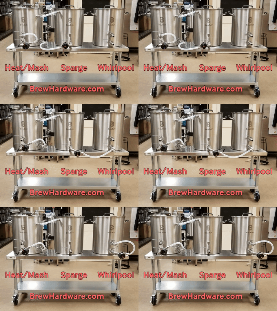
Here's what I have planned...

3.vessel.system.jpg


All fluid transfer connections are positioned at zero degrees at the front of the kettles, while the heating elements are positioned at 135 degrees (BK) and at -135 degrees (HLT). Does it make a difference as to the positioning of the fluid transfer connections on the kettle? Do the cooling coils, whirlpool arms, sparge arms, and pickup tubes need to be located away from the zero degree position or does it matter? I've seen kettles with both scenarios, but don't really know the logic behind it (if there is any).

Thanks in advance.
 
In many systems, you want your pick up tube on outer edge of BK so whirlpooling leaves the hot break in middle of kettle. For the same reason, you might not want your heat element too close to bottom.

I can't tell from your diagram where it is planned, maybe a top view would help
 
View from the top...

kettles.top.view.jpg


Please note, the pick-up tubes are not visible because they're under the cooling coil, sparge arm, and herms coil respectively.
 
If pick up tube is in center of BK, the practice of whirlpooling to get hot break to settle in center of BK will not work. Not saying it is the only way to do it, but how my rig works.

And if the heating element is so low in BK the it interferes with hot break "cone" in center, you might also get more hot break coming out of BK to fermentor.

I'd have BK pickup tube(1/2 NPT, fittings in stainless) on pretty much the same orientation as whirlpool arm in your picture, with a torepedo screen on it. When kettle is close to draining out, before looses suction, I slowly put a wedge of 4x4 under BK to get last of clear wort out.
 
Whirlpool returns shouldn't be up at the top of the kettles. They should be a couple/few inches off the bottom of the pot facing sidways.

You will hate cleaning the installed cooling coil in the boil kettle. Design it as a drop in so you can remove it and hose it off. Besides, you'll get a better final whirlpool after removing the coil.

Position the HERMS ports on a 45 degree towards the MLT and position the recirc return/sparge port on a 45 degree towards the HLT. The top of the HERMS coil doesn't need a valve. It will ALWAYS be connected to the sparge port.

That's about all I have to say about it.
 
Well, dang. Didn't even think about the heating element interfering with the trub cone. Looks like I need to decide upon a circular heating element. Just wondering if I can find an element with at least 5,500 watts that will fit the diameter of the kettle and spaced about an inch from the kettle wall. Good thing I haven't drilled for the elements yet! So, for the whirlpool return, can't the pickup tube be used for that or does it need to be a separate port and valve? The pickup tube comes off the bottom ball valve, is basically a 90 degree elbow, extends out about 3/4" from the kettle wall, extends down to 1/8" from the kettle bottom and darned near drains the kettle dry. As for the cooling coil in the BK, I will be using a rotating CIP ball in the hopes of making the cleaning easier. Also, forgot to reiterate my original question; is there anything wrong with having all the ports lined up at the front of the kettle? Thanks again for all the advice, folks!
 
Last edited:
Heating elements have no negative effect on trub cone formation.

The pickup tube drains the kettle and feeds the pump. The whirlpool return comes from the pump and makes the liquid spin.
 
A few more questions...

Bobby_M: ...The top of the HERMS coil doesn't need a valve. It will ALWAYS be connected to the sparge port...
Wouldn't I want to feed the herms coil (and the cooling coil for that matter) from the top down so as to reduce the resultant pressure against the pumps? Like this (gold arrows)?
flow.png

In addition, I've been thinking about the incorporation of a grant between the MLT and the pump (gravity to the grant) in order to help prevent stuck mashes. Thoughts?

Bobby_M: ...Heating elements have no negative effect on trub cone formation...
If the heating element is as pictured in my top view (post #3), how would that not affect trub cone formation as it passes through the center of the kettle?

Last, but not least, does anyone know of a circular heating element (something along the lines of a BoilCoil or SlingBlade) that will fit a 15-1/2" diameter kettle, but with at least 5,500 watts (more is ok)? I've been looking all weekend and just can't find anything that will fit. They all seem to be lower wattage at that diameter.

As always, thanks!
 
A few more questions...


Wouldn't I want to feed the herms coil (and the cooling coil for that matter) from the top down so as to reduce the resultant pressure against the pumps? Like this (gold arrows)?
View attachment 692311
In addition, I've been thinking about the incorporation of a grant between the MLT and the pump (gravity to the grant) in order to help prevent stuck mashes. Thoughts?


If the heating element is as pictured in my top view (post #3), how would that not affect trub cone formation as it passes through the center of the kettle?

Last, but not least, does anyone know of a circular heating element (something along the lines of a BoilCoil or SlingBlade) that will fit a 15-1/2" diameter kettle, but with at least 5,500 watts (more is ok)? I've been looking all weekend and just can't find anything that will fit. They all seem to be lower wattage at that diameter.

As always, thanks!

It makes no difference if you pump into the bottom or top of the coil. I absolutely hate using more hose length than necessary (even though I make more money when people over-buy tubing. Here's the system I typically build when someone wants a 3 vessel electric HERMS. Look at that connectivity efficiency!

giphy.gif


If you're seeing the GIF animation, it's cycling through the three brewing modes Strike/Mashing, Sparging, and Boil Whirlpooling. The system has less than 4 feet of silicone total.

All I can tell you is that I personally use an electric kettle with a ripple element so I have that personal experience but everyone I know with an electric kettle gets perfect trub piles despite the ripple element in the middle. It just doesn't affect it.
 
So, in your GIF, as pertains to the BK and the HLT whirlpools, they are mere inches apart. Will that generate enough "mixing" action or do we simply only care about whirlpool and not a constant recirculation throughout the entire volume of the kettle (especially when it comes to uniform temperature throughout the coils)? Thanks again.
 
The only thing the whirlpool return needs to do is to generate a decent rotational movement of the whole volume of liquid. That motion creates currents in the kettle that fully mix and homogenize the temps in the HLT and form the trub pile in the BK. In my BIAB rigs my drain and whirlpool return are at the same height, a mere 2" off the bottom. High mounting these are just a recipe for unnecessary oxygenation of your sparge water and wort.
 
Excellent! Thanks again, Bobby. The knowledge and suggestions are greatly appreciated! (and putting up with all the questions even more so!!!)
 
With an electric kettle (HLT or BK) and a RTD (or other type) temperature sensor, is it okay to locate the temperature sensor directly above the heating element (about 4" above) or should these be offset by a number of degrees around the circumference of the kettle? (Assuming the heating element is a straight or ripple element vs circular or sling blade).
Also, are there any (other) advantages (or disadvantage) of a circular heating element over a straight or ripple element? One obvious advantage in a BK would be to better accommodate an immersion chiller without setting it directly on top of the heating element.
 
The main disadvantage of circular elements is cost and secondarily the fact that they all install in a proprietary manner which would make it potentially difficult to retrofit a replacement should that type of element get discontinued in the future.
 

Latest posts

Back
Top