ITC 1000 Wiring Help

Homebrew Talk - Beer, Wine, Mead, & Cider Brewing Discussion Forum

Help Support Homebrew Talk - Beer, Wine, Mead, & Cider Brewing Discussion Forum:

This site may earn a commission from merchant affiliate links, including eBay, Amazon, and others.

MotivationDedication

Well-Known Member
Joined
Nov 19, 2010
Messages
155
Reaction score
11
Location
Lafayette
Hey all!

Looking for a little assistance in wiring my ITC-1000F. Ideally I had planned to wire in a fan to activate at the same time as the keezer, so that the fan wouldn't run 24/7, but would run on occasion. I've posted the wiring diagram I'm using (bare with me, it's a bastardized version of what I currently have rigged up), however I'm only receiving 12-13v once activated. I've tried a number of configurations before resorting to just posting here and asking for help, but I've run to my wits end.

Also, if anyone knows how to cross-post this to another subforum (Electric Brewing) I would happily do that. Hate to just post it twice.

Any assistance would be appreciative!

Thanks!
Diagram.jpg
 
Without a heating element in a kettle, this isn't an Electric Brewing problem :)

Anyway, looking at the switched neutral through the Cool relay (and cringing...but moving on) that circuit should totally work as drawn.
And I'm having difficulty conjuring any two points one could connect a DVM and see 12-13 volts...

Cheers!
I agree the circuit should work as wired. As day_trippr says, switching neutral (with the relay in the ITC-1000) doesn't meet code. You should really switch things around so that the relay switches the hot line.

By any chance did you follow a wiring diagram from InkBird that showed switching the neutral? InkBird originally wired the ITC-308 to switch neutral instead of hot. I called them out on it, and they changed the way they built future product.

Brew on :mug:
 
Here is the exact diagram I followed. I'll swap the layout so that the ITC is switching the hot line, then leads into the cooling device (on the neutral side) and see if that helps. I've plugged in a surge protector and have a construction light temporarily running in the place of the freezer (didn't want to fry my new freezer because of my own ignorance, might still end up doing it).

As always I appreciate the input.

IMG_1998.JPG
 
Last edited:
Ok, that drawing doesn't distinguish between hot and neutral, but it should. Since you had only the information in that drawing, you didn't make any mistakes.

Brew on :mug:
 
Ok, further info on this that may help with troubleshooting.

Switch seems to be activating correctly....

20200511_181857.jpg


But these readings don't seem right to me. Hot and neutral poles show ~9-10V, while either left/right and ground show 110v.

20200511_181700.jpg
20200511_181634.jpg


Am I crazy? Shouldn't the hot/neutral poles together equal 110v, not the way its showing in my case?
 
OK, I think I'm following, but I'm not sure I posted clear enough pictures to show where my concern is.

If I'm tracking, the following table helps show what I should be seeing, and then what I’m actually seeing:

Multi-Meter Prong 1
Multi-Meter Prong 2
Proper Reading
My Reading
Hot​
Neutral​
~ 110-120V​
~10V​
Hot​
Ground​
~ 110-120V​
~ 110-120V​
Neutral​
Ground​
0 V​
~ 110-120V​


Follow-up pics, better showing my reading locations:

20200511_183342.jpg


😆
20200511_183326.jpg


Sorry, I'm a worse photographer than I am electrician.
 
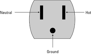
No way around it, the receptacle has to be miswired to get the readings in that table. If you changed "Hot" to "GND" and vice versa, the readings across each set of pairs makes sense.

Disconnect the power from the entire system, set the meter to resistance, and trace the wires from the receptacle back to wherever they're coming from...

Cheers!
 
Oh man, that wiring diagram is making the hair on the back of my neck stand up, though the diagram from the manufacturer is unclear. First off, I suggest running your cooling and and fan through a relay, and not rely on the dubious amp rating of the dinky little switches in your controller. I'm afraid of those things wearing out. Here's the diagram I did for my keezer controller - I used terminal blocks for the "busses" below, as that helps me keep the wiring straight in my head, but you could use wire nuts too. It would be easy to wire a fan in parallel with the switched keezer outlet in the diagram below. I added a general outlet in case I wanted to plug something else in, obviously not necessary.

If you are not going with a relay, then I would wire your setup with the hot wire on the line side of those switches in your relay, and just send the neutral back on the other side of the cooling device (almost like your diagram has hot and neutral switched). I'm not sure why that makes me feel better (I guess it is not having a switched neutral), but I've had a couple of beers already...
1589320178361.png
 
OK. Just as a follow-up for those who may search for this in the future. I went to re-wire to adjust for recommendations all you fine fellows gave..... I attempted to power up to backtrack and test for resistance and the ITC wouldn't power on. 120V at the input for the device, but dead in the screen. Powered on before, now I wouldn't.

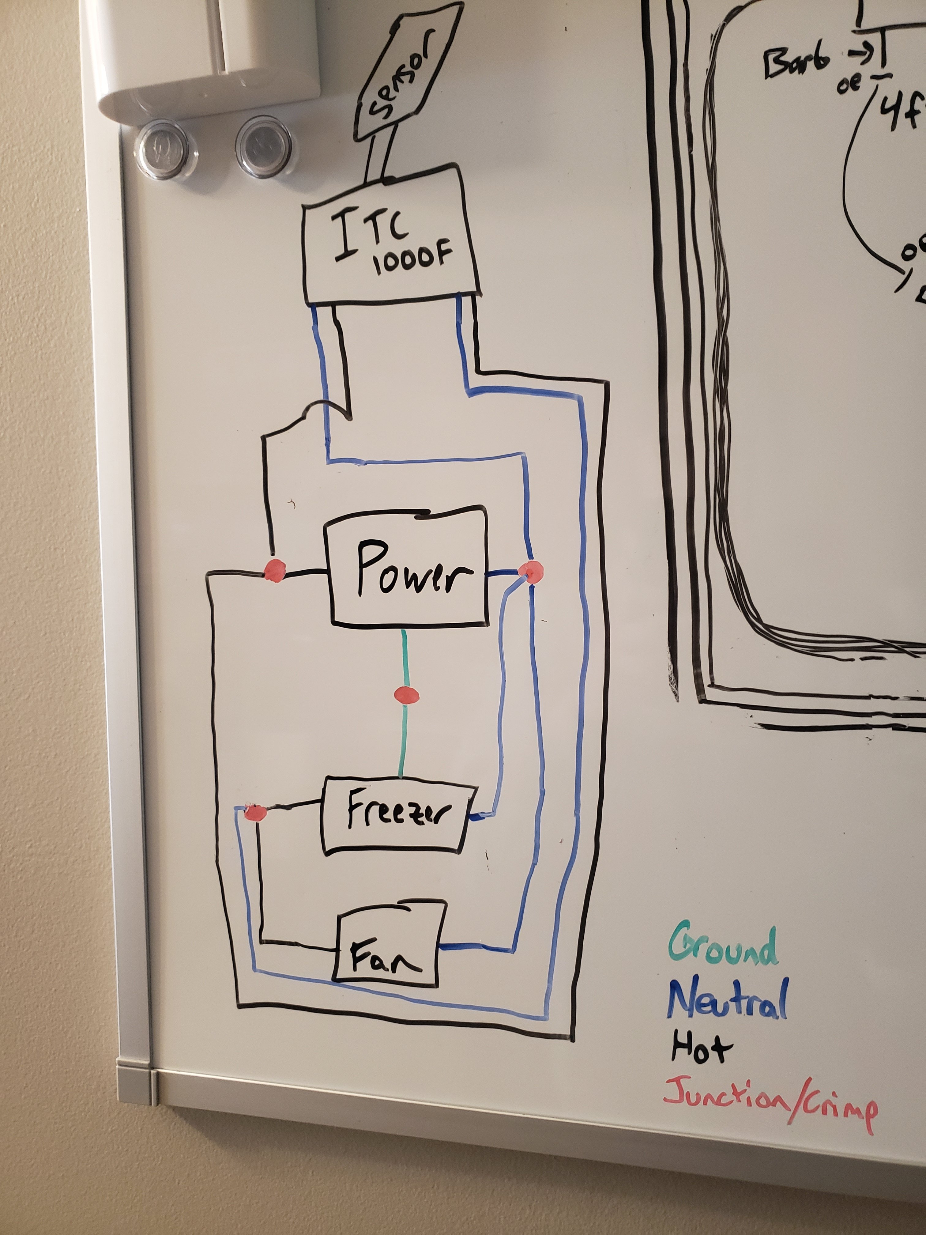
Returned the device and got a new one. Rewired similarly to before (diagram used is below) and everything is well.

Thank you all for your patience and help.

20200515_111426.jpg
 
The blue wire coming out of the ITC-1000F on the right (relay terminal) should be black, as it is a (switched) hot, not a neutral.

Brew on :mug:
 
The blue wire coming out of the ITC-1000F on the right (relay terminal) should be black, as it is a (switched) hot, not a neutral.

Brew on :mug:

Ok! I wondered if that should be black or blue. Makes sense to be black (since it is the hot source for the freezer, and that's how it functions). Thanks for the feedback. Now I know how to properly diagram it!

:mug:
 
Convention actually prefers red for switched lines, but black is acceptable...

Cheers!
That would work in a 120V app, but in a split phase 240V, I use black for one phase and red for the other. Going thru a switch doesn't change the wire color.

Brew on :mug:
 
Black and red are a good practice for 240vac as opposed to black/white, but this is 120VAC, and switched hot = red is preferred as it's highly indicative of the circuit nature...

Cheers!
 
Back
Top