iSpindle - DIY Electronic Hydrometer

Homebrew Talk - Beer, Wine, Mead, & Cider Brewing Discussion Forum

Help Support Homebrew Talk - Beer, Wine, Mead, & Cider Brewing Discussion Forum:

This site may earn a commission from merchant affiliate links, including eBay, Amazon, and others.
@springing Yeah, I ordered some yesterday and stumbled on that you tube video as well. Just waiting for my parts to turn up now..
 
Anyone know a good place in the US to purchase the xl preform needed for the pcb you listed just above from pcbway? I just ordered a bunch of boards to get the project started!
Neil
 
Anyone know a good place in the US to purchase the xl preform needed for the pcb you listed just above from pcbway? I just ordered a bunch of boards to get the project started!
Neil

If you go to the link there is a link in the same page to the containers

That is not a U.S. supplier, however they may ship to the U.S. You may have success ordering it from eBay. The same supplier I purchased my PETlings from offer the XL. (I ordered the XXL for the 3D printed sled.

I've yet to see a U.S. based supplier of either the XL or XXL PETling.

Edited to Add: Interestingly, the eBay supplier I recommended (uniquegeocaches) is located in Lithuania (so is the website listed on the PCBway listing)
 
Last edited:
Yeah I'll just have to pay out the butt for shipping. I was hoping there was a us distributor. I have the rest of the parts purchased. I snagged enough to make 10 (I'll probably only ever use 4 but...)
Neil
 
I just bought the old pcb yesterday lol. Oh well the new one costs $2 more with the addition of that 18650 holder. One thing I noticed is the silk screen text on pcb says 1043P (ploarized) while the link provided takes you to the regular 1043 (leaf spring) contacts. I'm not sure which is correct (I'm guessing it has something to do with a protected cell vs unprotected and if it has a button for positive contact or not). Oh well the old pcb has at least been tested so when China gets my stuff here I'll have another project to build.

Neil
 
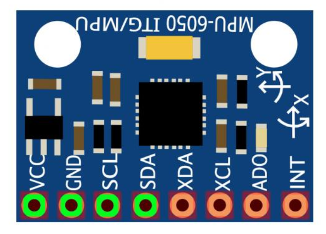
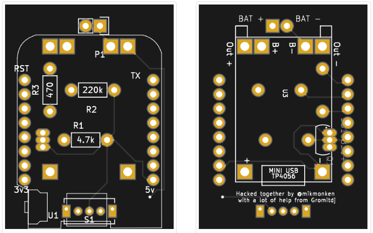
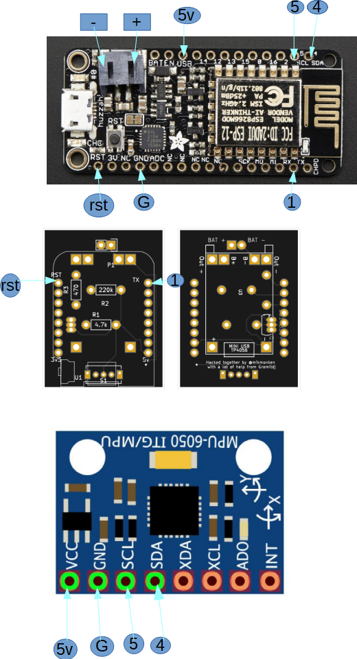
Does anyone have a wiring printout for:
1. MPU-6050
2. iSpendel PCB v2.1
3. Feather Huzzah ESP8766

upload_2018-7-16_20-33-14.png

upload_2018-7-16_20-33-40.png


upload_2018-7-16_20-39-1.png
upload_2018-7-16_20-33-14.png
upload_2018-7-16_20-33-40.png
upload_2018-7-16_20-39-1.png
 
Also with reed switch does it need the magnet to stay on or does it work like a pc switch, move magnet close then away to turn on then close and away for off?
 
Does anyone have a wiring printout for:
3. Feather Huzzah ESP8766

I highly recommend buying a Lolin D1 Mini (the company renamed itself from Wemos a few months back) and using that /w the @Mikmonken and @gromitdj 's iSpindel PCB over going down the Feather Huzzah route. The D1 Mini is much smaller and is the main chip in use amongst people who have built iSpindels whereas you'd be pretty much on your own (without a pre-made PCB, pre-designed sled, etc.) if you chose to use the Feather.
 
Let me know if those work or not. I am still waiting on mine to come in from ebay supplier. They look to be closer to the XXL vs XL ones in size.
Neil
 
Let me know if those work or not. I am still waiting on mine to come in from ebay supplier. They look to be closer to the XXL vs XL ones in size.
Neil

I won't have all the parts in (nor will I have the sled ready) when it comes in, I can take measurements of the tubes and post them here.

My initial plan will be to measure the tubes and compare the dimensions to the sled CAD before I 3D print it. Then, filling the tube with paper towels along with a small amount of weight and drop it in water, just to be sure that the lids are water tight.
 
Just wanted to follow up that I received those jumbo “toy” test tubes I linked to a few posts back. They are 152.55mm in length without the cap, 154.12mm with the cap and the inner diameter of the tube is 35.45mm. The outer diameter is 38.48mm where the cap itself is 45.92mm od.

I still haven’t received all my parts yet to check for actual fit, but, these tubes might just work!
 
My tubes came in today as well. Ordered on 11th shipped 12th and delivered on the 23rd from the ebay vendor. Pretty decent shipping if you ask me. Beat the other parts so far.
Neil
 
Has anyone got any recommendations as to where I should print the slides? Cheapest i found was $40 for 5
 
That is the XL PETling. I ordered the XXL PETling from the same vendor and it fit the sled perfectly.

XXL PETling: 5 pcs XXL set of BIG PET Micro Geocaching container geocache preform Soda bottle

Sled: iSpindel Sled

How much weight did you add/where? I got the XXL petlings, but printed sleds that had a threaded bottom for a nut/washers - I had to cut off pieces of both sides of the sled to get it to fit, and even then could only get one nut & washer on (and didn't get a 20-25 degree tilt in water). Just wanted to make sure everything was good with the sled you linked to
 
How much weight did you add/where? I got the XXL petlings, but printed sleds that had a threaded bottom for a nut/washers - I had to cut off pieces of both sides of the sled to get it to fit, and even then could only get one nut & washer on (and didn't get a 20-25 degree tilt in water). Just wanted to make sure everything was good with the sled you linked to

I added 15 grams. 10g at the lowest possible point and used trial and error to locate 5g in the middle. You can see where my weights ended up in the following picture.

2018-04-15 22.04.49.jpg
 
Does anyone know what changing the 230k resistor value to 220k will do? Obviously change the a0 reading... will it change it enough to screw things up? I can't even find where to get a 230k ohm 1/4 watt 5% resistor...

Neil
 
The iSpindle GitHub and the screenprint on the PCB that I uploaded to pcbs.io both call for a 220k resistor.

BTW, there is a 330 Ohm resistor listed on the GitHub page (470 on the PCB), but I recommend going with the BAT43 diode instead.
 
/me smacks head..

I purchased this v2.6 board from pcbway (https://www.pcbway.com/project/shareproject/W10971ASK36_iSpindel_v2_6.html)
I was referencing this original image from the github (http://www.ispindel.de/docs/circuit_diagram_en.html)

So I see now that the pcb I ordered calls for a 220k (So I should be good). My only issue is I can get it to toss data to the ubidots page. Only problem is it only does it once after being powered up... I can see the data there as referenced below. I have the configuration set to upload every 20 seconds (as I still need to calibrate this). Yet the data never changes until I reboot it and then it will upload one value and **** itself or something..

The other issue I have is I built it per spec and I see it sitting at 18.76 degrees vs the 25 others claim to have got when building... I am not sure how I am so far off. I used a samsung 30q battery.. Any hints there?

Thanks,
Neil
Capture.PNG
 
I can't help you with the angle in water: I used the shield mikmonken and I designed, and I had to move some weights around to get it to sit @ 20° in water.

However, I believe some have experienced an issue with the 470 ohm (or 330 ohm) resistor that prevents it from coming out of deep sleep. That is why I recommend the diode.
 
20180806_211150.jpg
Hmmm you got me thinking... a diode has polarity vs a resistor... I wonder if I soldered it in reverse? Is that possible? I know just enough ti be dangerous here lol..
Neil
 
View attachment 582570 Hmmm you got me thinking... a diode has polarity vs a resistor... I wonder if I soldered it in reverse? Is that possible? I know just enough ti be dangerous here lol..
Neil

Diodes only allow current to flow one way, current flows from Anode to Cathode (the cathode is the side with the band on the cylinder).

The cathode of the diode (band side) should be in D0 of the wemo, the anode side (without the band) should be in the RST of the wemo.
 
Last edited:
View attachment 582570 Hmmm you got me thinking... a diode has polarity vs a resistor... I wonder if I soldered it in reverse? Is that possible? I know just enough ti be dangerous here lol..
Neil

I don't know what the schematics of that board are, but, the RST is the last pin to the right of that picture and the D0 is the third pin in from the right. If the traces from the diode correspond to the pins, then, yes, your diode looks to be in backwards.
 
We good to go! Thanks for the help everyone!! I had to move the weight up quite a bit from where it is silk screened on the pcb but eh.. Now to calibrate and figure out what I would like to capture/log the data with. Fermentrack looks like it might be the best route to go.

Neil
 
I've tried reading every comment on this thread, but I'm still at a loss. I've assembled my unit, but I get stuck there. I'm not sure if I am missing something in the guides due to translation or what, but I can't seem to get further. I have flashed my unit with the most recent firmware (posted yesterday I believe). According to the NODEMCU software, it was successful. I try connecting to the access point (mine is named ESP_0E2A50 instead of iSpindel that the guide says to use), but when I go to 192.168.4.1 nothing happens.

I'm sure I am missing something simple, but I'm so frustrated now that I am about to throw it in the trash and forget about it......except we all know I won't do that.
 
You don't connect to it like a normal I.P. address in a web browser. Instead, you have to put the Wemos into A.P. mode by pressing the reset switch. The LED on the wemos will blink every second or so when it is in A.P. mode. It might take a couple of resets, but I usually have good luck if I press it once, then press it again within a second or so.

Once it is in A.P. mode you connect to it as if it is a wireless network. (you should see "iSpindel", or perhaps "ESP_0E2A50" as an available network in your list) Once you select it, you should see the configuration page in your web browser.

Hope this helps.
 
Thanks for the reply @gromitdj I just hit the reset button a few times, I get a blink, then nothing for 25 seconds. I tried reconnecting to the ESP connection on my laptop and phone, but I don't get a configuration page.
 
Does it look like this?


This is what mine looked like, and it actually wasn't flashed correctly. You can see my struggles in post #426 of this thread. If you want to take a look at what my NodeMCU settings were I can send the images to you.

If not and it blinks a little longer and appears to be "booting up" or sending data, shortly after it blinks, push it again. It should go into A.P. mode. If you could try to get a video of it, it may help.
 
OMG Thank you so much @gromitdj

I'm not kidding when I say I have been working on this for well over 10 hours over the last few days. I couldn't see your screenshots (might be an issue on my end) but I changed the firmware line of the Config tab to also be 0x00000, it flashed twice on it's own and boom! iSpindel showed up like it should!

If you are even in the Nashville area I owe you dinner!
 
No worries, glad you got it working and glad I could help.

ETA: The issue is not on your end, I think they were lost in the HBT forum switch-over awhile back. If anyone is having a similar problem, I would be glad to re-post them.
 
Back
Top