iSpindle - DIY Electronic Hydrometer

Homebrew Talk - Beer, Wine, Mead, & Cider Brewing Discussion Forum

Help Support Homebrew Talk - Beer, Wine, Mead, & Cider Brewing Discussion Forum:

This site may earn a commission from merchant affiliate links, including eBay, Amazon, and others.
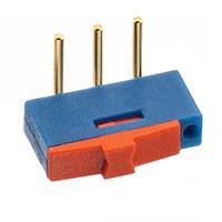
No I didn't, but it explains how I've made a mistake, I think I've ballsed something up to do with the switch where I thought that the middle pin of the switch needed connecting to the live which I thought made no sense at the time.
what is the proper way to connect the switch?
MFG_450302014072_sml.jpg

attachment.php

I connected my switch with power to the center, charger out + to the left and nothing on the right.
 
GromitDJ has been helping me a lot with this, and i hope to have a board developed soon.

You're right the connection fro the middle to the top switch plug is and it shouldn't be connected to anything, i think effectively the switch toggles whether the battery is charging or powering
 
How do you flash the D1 after everything is assembled? I plug in the USB port with the charger switch in the off position and nothing happens with the D1
 
How do you flash the D1 after everything is assembled? I plug in the USB port with the charger switch in the off position and nothing happens with the D1


The wemos needs both power and a data connection to be flashed. It sounds like you're not getting power to it.

If you press the reset button on the wemos does it flash blue briefly?

If not try switching it the other way. As I mentioned I messed my switch up to start so had to have the power attached to the lipo charger to get mine flashed.
 
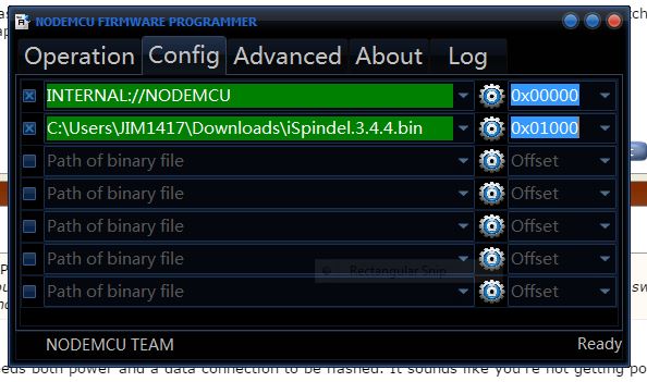
This is how I flashed the D1. Now what?

Firmware Release flash

-Install Wemos driver
-Download and start NodeMCU-Flasher
-Download newest release of / bin folder
-On the "Config Tab" select the .bin file by clicking on the gear (i only edited the first line myself)
-On the "Operations Tab" a COM Port to the Wemos should show if the drivers are installed correctly
-Click on "Flash" and you will see the progress bar start moving

Ubidots

To start, you must create a free account at Ubidots.com
Next, you must go to the menu "API Credentials" to get a Token to be used by the iSpindle to authorize writing data to the Ubidots account. Write this down.

Portal

Then just follow the portal instructions here

After you setup everything you should see your iSpindel on the "Devices" tab on the Ubidots website, hope this helps ;)
 
Just finished building an iSpindel and it seems to work with Ubidots, but I haven't tried to calibrate it yet. I used the drawer design "Drawer-combo.stl," which I had to drastically dremel to fit in Learning Resources' six-pack of Jumbo Test Tubes (https://www.amazon.com/gp/product/B004ALRJKE/?tag=skimlinks_replacement-20). It looks like the inner diameter of the test tube is slightly over 35 mm, but I managed to squeeze it all in. I removed the diode from the Wemos D1 and the LED from the GY-521. I didn't, however, connect the orange wire from IN+ of the TP4056 to the Wemos (I still don't understand why the connection is necessary). When I added about 28 grams of weights to the side of the drawer opposite the battery, I was able to get a consistent tilt angle of 4.5 degrees in water. The overall weight of my iSpindel is 176.5 grams. Thanks to everyone in this thread for sharing their information and experiences.
 
Last edited by a moderator:
This thread has been a great help in getting things up and running. At the moment I have the circuit built and connected through to ubidots and now have to print the sled to get it in the tube. It all appears to be working correctly so far.

However I've done a few things differently to the original design.

1. I haven't flashed the wemos. What is the purpose of flashing? Is it just for new standard wemos firmware or is it a specific ispindel firmware?

2. I am using a wemos battery shield rather than the basic TP 4056 (https://www.wemos.cc/product/battery-shield.html). This looked like it required less work than the TP 4056. I am able to (according to the docs) charge the battery at the same time as running the wemos using this shield. I guess this removes the need to remove the diode on the wemos itself or include the toggle switch. Has anyone had experience with this shield or does my reasoning appear correct?

3. The GYU led is still connected. Is the purpose of removing this purely to increase battery life?

Thanks
Not sure it will fit in the tube with the shield.The TP 4056 is on the opposite side of the D1 and the MPU-6050 is stacked on top of the D1
 
I had the same sizing issue a few others had with the XL PET tube I ordered off eBay. I slimmed down the design on thingiverse and uploaded the new model here: http://www.thingiverse.com/thing:2231986

This is the tube that I ordered off eBay.

http://www.ebay.com/itm/XXLBIG-PET-...1dcdcc7&pid=100011&rk=1&rkt=5&sd=142295113730

Awesome thanks!

I'm having one made and have the tube ordered. Being Easter everything is taking some extra time, not to mention the extra time to get the stuff to Australia.
 
Hi All,
I know this may come over as a bit cheeky, but I would like to ask if anyone has an Eagle CAD "SCH" and "BRD" files for a PCB (31mm wide x 33mm long) to fit the iSpindel Drawer and is happy to share these with us please?

Thanks.
 
Firmware Release flash

-Install Wemos driver
-Download and start NodeMCU-Flasher
-Download newest release of / bin folder
-On the "Config Tab" select the .bin file by clicking on the gear (i only edited the first line myself)
-On the "Operations Tab" a COM Port to the Wemos should show if the drivers are installed correctly
-Click on "Flash" and you will see the progress bar start moving

Hi all, can you please help me? I do it exactly like this, but I am not able to flash wemos. Flasher recognizes the port, wemos starts to blink faster but there is no progress. After half hour I turn it off. No MAC appeared. I tried it on several PCs with various windows. I installed driver etc. I can see wemos as wifi point in PC so it seems to be ok.Do you know where is the problem? I am a layman :)...
 
Hi All, I have a problem with flashig wemos with esp8266flasher. I installed driver and did all steps. Flasher recognized port, wemos started to blink faster but then no progress appeared. I turned it off after half hour. I see wemos as wifi spot so I think it is ok. Do someone know what is the problem? Is there other alternative to flash wemos (sorry I am a layman)? Thank you.
 
Hi All,
I know this may come over as a bit cheeky, but I would like to ask if anyone has an Eagle CAD "SCH" and "BRD" files for a PCB (31mm wide x 33mm long) to fit the iSpindel Drawer and is happy to share these with us please?

Thanks.


I hope to have a 30 x 40 board towards the end of this week, I'll share the files and you can try and squash that into a 31 x 33 if you want to
 
Hi Mikmonken,
Thanks in advance for the files, as I am sure that I can then modify the size to suit.
 
Did you get anything out of it before you killed it? My bits are arriving but very slowly
I stuck the battery in the tube to see how it floats. I can see why they need weights to get it to 25 deg in plain water.


I can't find the original link that talks about the angle being between 20-25 deg. So far with 25gs of weight move managed to get it to 23View attachment ImageUploadedByHome Brew1492413398.012585.jpg deg and trying to shift the centre of balance.

Can you post a link to the original reference?

It's all up and running which is good. On my second one I've left the led on the gyu so I can see it's powered.
 
The 25 deg I got from the hobbybrauer.de forum. Google translate lets you read the pages enough to decipher the latest discussions about ispindle GitHub.
Sorry can't be more specific as my home internet is down atm. Using the phone.
 
What, I can deduct from the hobbybrauer.de forum is that you need to set the iSpindel at between 20-25 deg at 0 Plato to perform / allow the calibration test to be set up properly?

I trust others will agree that my interpretation of this from the hobbybrauer.de forum is correct?
 
Hi, I sovled the problem with flashing wemos. It was a mistake in soldering. Now it works, but the problem is it sends the data to ubidots only when I turn it on or reset it. I set the interval to 10s (and tried it several times with various intervals). Someone else with this problem or some solution? Thanks a lot in advance.
 
What, I can deduct from the hobbybrauer.de forum is that you need to set the iSpindel at between 20-25 deg at 0 Plato to perform / allow the calibration test to be set up properly?

I trust others will agree that my interpretation of this from the hobbybrauer.de forum is correct?

I got the information from this document:

https://github.com/universam1/iSpindel/blob/master/docs/iSpindelPCB.md

at 19.

19. Spindel trimmen

Vorschlag für etwa 25° Neigung in Leitungswasser
Vorschlag für etwa 15° Neigung in Leitungswasser

google translated it to

19. Trim the spindle

Suggestion for approximately 25 ° inclination in tap water
Proposal for approximately 15 ° inclination in tap water
 
OK with a little (read a lot) of help from GromitDJ I've pulled together a first bash of the board design, all the files are here hopefully that link works, the board is 30mmx40mm and should slide in nicely to the sled, and the switches should work too (unlike the shoddy soldering on the board I'm currently using.

I've ordered a few board from pcbs.io and if it all works out I'll drop a link to the shared board.

comments suggestions appreciated.

Cheers

View attachment Schematic - iSpindel.pdf
 
OK with a little (read a lot) of help from GromitDJ I've pulled together a first bash of the board design, all the files are here hopefully that link works, the board is 30mmx40mm and should slide in nicely to the sled, and the switches should work too (unlike the shoddy soldering on the board I'm currently using.

I've ordered a few board from pcbs.io and if it all works out I'll drop a link to the shared board.

comments suggestions appreciated.

Cheers

Hi!
A very good schematic, just one question!! The Wemos power supply is attached to the 5V pin instead of the 3.3V pin?
 
Hi!
A very good schematic, just one question!! The Wemos power supply is attached to the 5V pin instead of the 3.3V pin?

It's based on the original wiring that is on GitHub so the connections mirror that, I don't think anything is connected to the 3.3v pin on the original circuit.

I could be completely wrong though.
 
Hi Mikmonken,

Thank you for sharing the schematic with us, which is very much appreciated.

Cheers.
 
This is something that I want to check (currently I'm waiting by the slow Chinese boat xD with my components).

In theory with the battery and the charger you will get a voltage around 3.7V at the battery output so I don't know how will work the 5v voltage regulator only with 3,7V. Instead using the 3,3V pin the input voltage regulator on this pin will works fine.

Anyway this only theory I have to check it by myself
 
I have checked the Wemos schematics and the input voltage regulator at 5v pin convert the voltage to 3,3V and the minimum input voltage for this regulator is 2,2V, so in consequence with 3,7V it will work fine :)
 
Using 80mA (total SWAG) as the worst-case load for the D1 Mini and the rest of the components, the RT9013-33 LDO spec shows the 3.3V output will start to track the input voltage once the battery drops to 3.35 volts.

That means once the battery voltage drops to 3.35, every further drop will be reflected linearly at the regulator output, until the battery drops below 2.2V where the RT9013-33 totally loses its mind.

Of course the Mini may have already taken a dirt nap around 2.97 VBAT.
So there's not a lot of head room in this scheme...

Cheers!

A very good explanation!!

Cheers!
 
But as a side note to that using the specified battery and setting log intervals for 30 mins, battery life is noted to be around 3 months.
 
I doubt it will work since even Microsoft's on-line version doesn't. The excel might have something in C# or VB because the on-line version Excel complained something about ActiveX or VB. Never mind, I've found my solution. Even iSpindel does it in other way, I am going to stick this way unless it doesn't work.


Spline was my first homework in Algorithm class and the first algorithm that came to my mind. I tried studying it on the internet, ( I was too lazy to find my text book.), but one thing kept bothering me: ERROR. The data we have has error in it and is nothing near precise. It didn't seem right to me to derive the coefficients by fitting data with errors. Therefore, I concluded that regression is the solution. I am lucky to find a Javascript library for regression, and the example code even has a chart.

https://github.com/Tom-Alexander/regression-js

This library also supports exponential and other regression. If my real data doesn't seem to be polynomial, I can adapt quickly.

@pocketmon did you ever manage to sort the issue with OS X and excel? I'm getting the error 400 code with Visual Basic and know it's an issue with Excel for Mac, so if you've worked out a way to calibrate that'd be great.

Thanks
 
@pocketmon did you ever manage to sort the issue with OS X and excel? I'm getting the error 400 code with Visual Basic and know it's an issue with Excel for Mac, so if you've worked out a way to calibrate that'd be great.


Thanks

nope. I just created a Javascript for it. I am not sure what algorithm the excel uses, but I can get the same coefficients by inputting the same dataset in the chart of the document.
 
Finally get the calibration done.

My iSpindel tilts around 37 degree in tap water with 20g at the bottom.
It will tilt like 5 degree with 25g at the bottom, so I have to stick the additional 5g at the center.

The result curve is more like a third order(x^3) instead of second order.

ispindel1.jpg


ispindel2.jpg
 
Did anyone try to make iSpindel with bluetooth (BLE) instead of wifi?
There is no access to wifi everywhere. Bluetooth needs less power. You could do something like beacon. Reading can be done by the application on the phone.

Does anyone have an idea what parts can be used for this?
 
Did anyone try to make iSpindel with bluetooth (BLE) instead of wifi?
There is no access to wifi everywhere. Bluetooth needs less power. You could do something like beacon. Reading can be done by the application on the phone.

Does anyone have an idea what parts can be used for this?

Yes. Please google Brewometer or TILT hydrometer.
 
I know this project, but it is commercial. I'm looking for a DIY idea.


I am just curious and have to ask... why? For $120 you get something that works and is supported. You would dump hours upon hours doing a one-off. Your time should be worth much more than that.

Now, if you wanted to do it just for the sake of learning, I could appreciate that. But if only for the end goal of having a hydrometer, you would save $120 but spend $1200 (or much more).
 
Because I can do exactly what I need (for me or for my friends). I know how to do it (except electronic, this is my weak point) and I like it (hobby? :))
 
Back
Top