InkBird ITC-1000F wiring

Homebrew Talk - Beer, Wine, Mead, & Cider Brewing Discussion Forum

Help Support Homebrew Talk - Beer, Wine, Mead, & Cider Brewing Discussion Forum:

This site may earn a commission from merchant affiliate links, including eBay, Amazon, and others.

SleepyBeer

Member
Joined
Apr 8, 2022
Messages
8
Reaction score
2
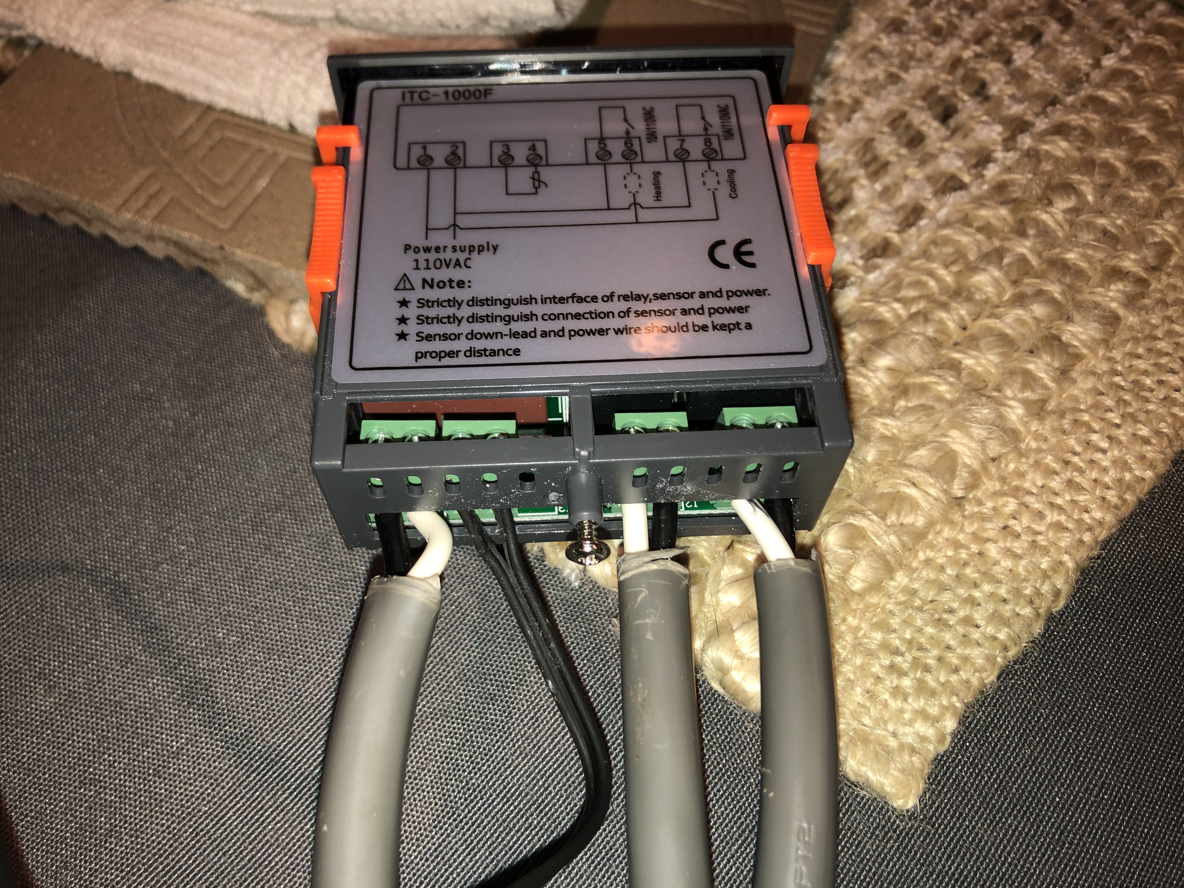
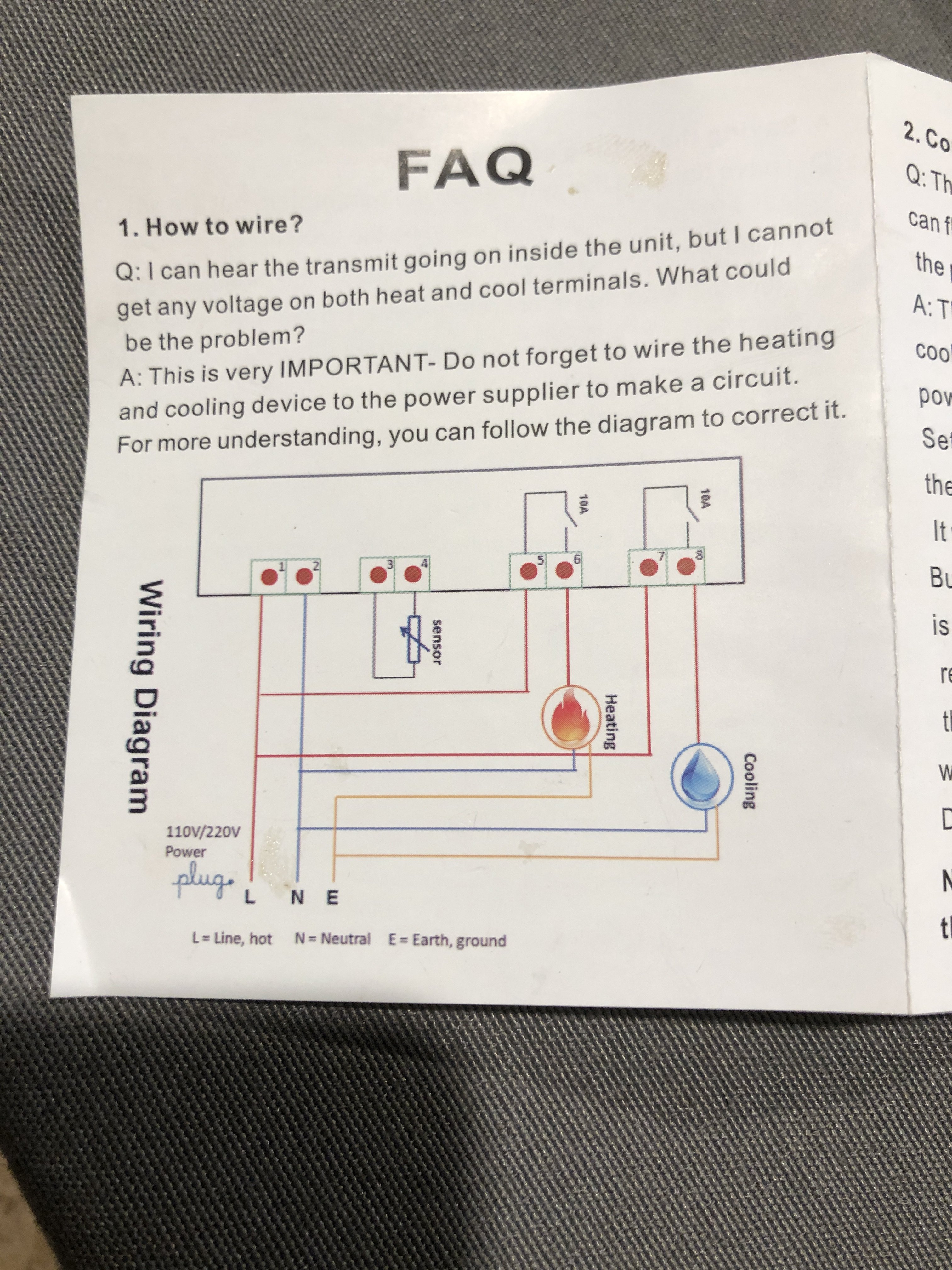
I wired up my Inkbird according the the color diagram that it came with. On the Inkbird itself there is a black and white different diagram.

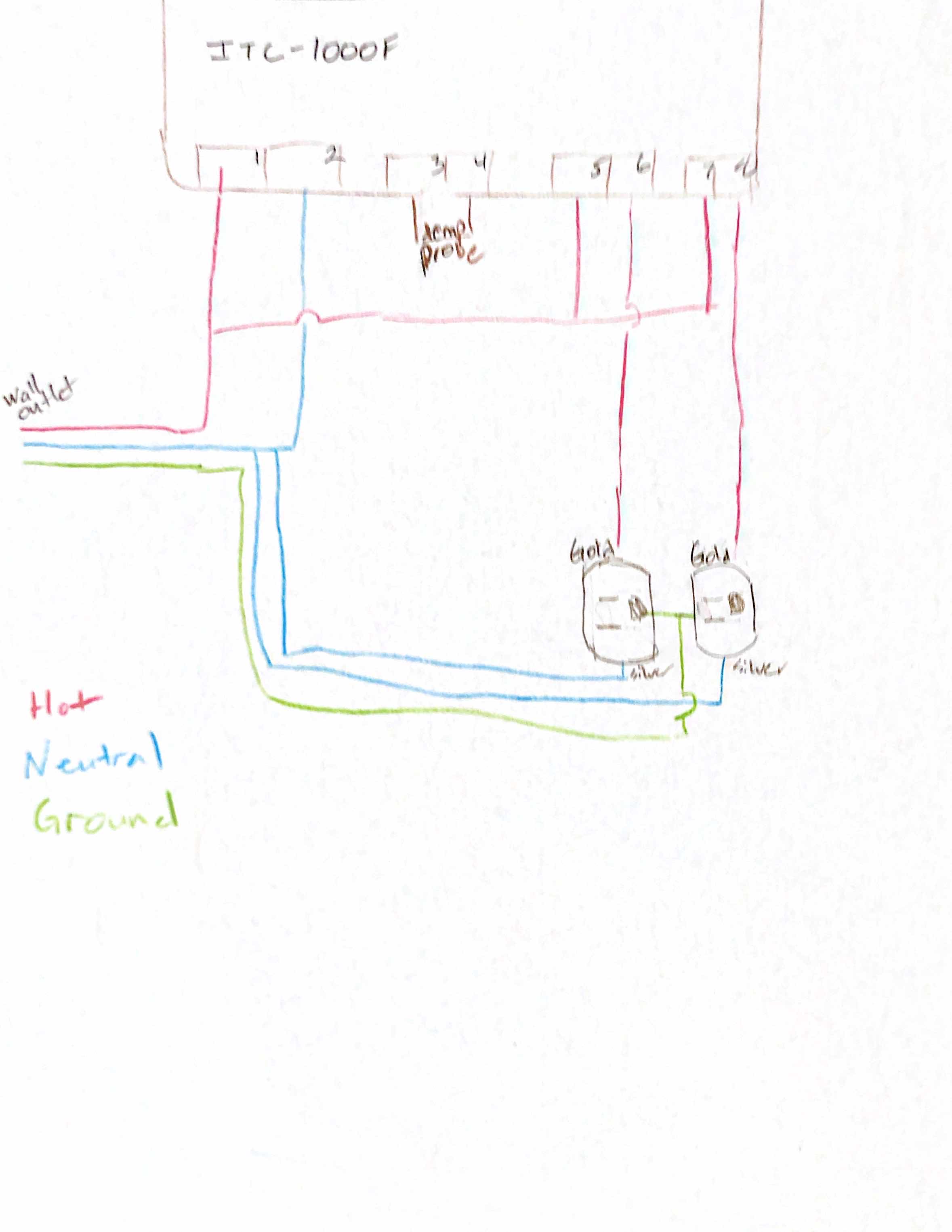
I brew in the garage, so I need cooling and heating. Cooling is an old Danby Kegorator and for heating I have a reptile heating element that I use in winter. So I am want to use both the heating and warming functions. I have a duplex outlet, one outlet will be for the Danby and the other the ceramic heating element-- I clipped off tab on the copper bridges so each outlet was separate.

My wiring was all correct, more than triple checked, and nothing was plugged into the outlets yet. I plugged in the Inkbird and got an immediate alarm, error and sparks from the hot line from the wall.

What happened? I thought I must have made a mistake wiring, but I traced every line over and over and it follows the diagram.
 

Attachments

  • IMG_0426.JPG
    IMG_0426.JPG
    2.3 MB · Views: 0
  • IMG_0427.JPG
    IMG_0427.JPG
    3 MB · Views: 0
  • IMG_0429.JPG
    IMG_0429.JPG
    3.7 MB · Views: 0
  • IMG_0425.JPG
    IMG_0425.JPG
    1.8 MB · Views: 0
It looks like you wired it by the diagram on the unit. It doesn't seem to agree with the diagram on the paper.

The paper seems to show all the line or hot wires to be connected to the left of each terminal block on the unit.

However, being that those blocks are probably just leading to internal switches, it might not matter.

I am by no means a electrician with any training. However I do quite a bit of playing one in my hobbies.

The pics of the other stuff don't tell much since we can't see where the wires are connected.

Maybe you could draw it out for us.

And, you really need to have grounds connected. If you aren't going to have grounds, you shouldn't use a grounded outlet to fool others that things are grounded. IMO & PSA
 
Last edited:
OK, I will draw out what I did, nd post it. Thanks for the response. Also I did have both outlets grounded. The terminals on the switches 5-6 and 7-8, I both sides are hot, the white wires I marked on the ends (can't see in picture), as they are a hot wire bridge so to speak to the switches.
 
The wiring on your drawing doesn't match what the actual wiring is in IMG-0429.JPG.

But still, I think those other connection on the unit are just switches and it doesn't matter what terminal you use... unless the device itself is grounded and they somehow depend on that with how they internally wired the switches.

Just bite the bullet and use two duplex outlets. Maybe you still didn't wire that correctly after breaking off the tabs.

And are you certain that what you are connecting to isn't pulling too many amps? For some things you need to look at the starting amps which will be much higher than the normal amp rating.
 
Last edited:
Inkbird gave 2 separate wiring diagrams, I don't know why??? i was using the color on in image IMG-0425.JPG

I haven't connected any loads to the duplex plugs yet. I have unwired almost everything, on next attempt will just wire one side to the duplex at firs to the cooling side and leave the warming circuit off.

I did put a voltmeter on the line from the wall, and was only getting 35 volts. The volts in the wall was 110 v. So will replace that power cord. Not sure what is going on there.
 
Figure out the low voltage on the wall outlet before connecting anything to it.

Might just be you had your voltmeter on the wrong selection. DC and AC don't read the same. And if you have a very old analog voltmeter/multi-meter, it can be easy to read the wrong scale.

I think it also makes a difference as to whether you measured to ground or neutral. But I'll have to go play with that to see.
 
I did put a voltmeter on the line from the wall, and was only getting 35 volts. The volts in the wall was 110 v. So will replace that power cord. Not sure what is going on there.
Well that aint right.

The terminals are not that robust on the stc. I tinned all my stranded wire to avoid any mishaps.
Unhook everything and start over. Check for continuity between 1 and 2 then just powering the stc with no load connections. It's possible you had or now have a defective unit.

By the way, mine is wired with hot on 1,5,7. Hot load is on 6 and 8. Just like the colored FAQ.

If all else fails...the 308 is only $35 or so and the wifi version lets you check temps from your phone and has a history temp line graph.
 
The wiring on your drawing doesn't match what the actual wiring is in IMG-0429.JPG.

But still, I think those other connection on the unit are just switches and it doesn't matter what terminal you use... unless the device itself is grounded and they somehow depend on that with how they internally wired the switches.

Just bite the bullet and use two duplex outlets. Maybe you still didn't wire that correctly after breaking off the tabs.

And are you certain that what you are connecting to isn't pulling too many amps? For some things you need to look at the starting amps which will be much higher than the normal amp rating.
Agree. Checked some sites and could not locate the amperage rating. Not saying that it's not out there but it's not easy to locate.
 
I got it working. Tallgrass was right. I have used a large gauge wire, and the contacts on 1 & 2 are small, and a copper strand was likely touching. I also replaced the extension cord I was using since it had a voltage drop.

If I had it to do over again, I would use a smaller gauge or Romex for most all of it.
 
Back
Top