I need some help on my panel - Single Vessel - 220v no neutral - limited power input

Homebrew Talk - Beer, Wine, Mead, & Cider Brewing Discussion Forum

Help Support Homebrew Talk - Beer, Wine, Mead, & Cider Brewing Discussion Forum:

This site may earn a commission from merchant affiliate links, including eBay, Amazon, and others.

Paulillo

Member
Joined
May 7, 2012
Messages
14
Reaction score
1
Location
Sao Paulo
Folks,
I`m building a 10 gallon single vessel system (like braumeister) but I have a few serious issues and i`m requesting all help you can give!!!!

The first and most serious problem is that i live in an apartment that has 220 V outlets limited in 20A and NO NEUTRAL. All those wirings are 4mm BUT I`m FORBIDEN to make any changes in this setup.
So I cannot have 220V+110V+Ground at the same time and the overall power input is low. I have a 12V 3A food grade pump with flow control that i`m planning to use, a REX C700 PID and a few low consuming signaling lights.

Due to my limitations I designed it with a 3.200W coil (220v - 14.5 A), pump (12v - 3A), PID (220v - 600ma).

The second problem is that i have a GVCI rated 32A - 30ma, but i pretend to use it as a human safety device, not peak protection. My doubt is if it will work on this setup and if I`ll be protected.

PLEASE I count on your knowledge and experience to help me to put this setup wright and don't burn my old house or burn myself.

Dear GOD P-J if you can listen to this humble mortal I beg for your help!
Thanks
Fabrizio

View attachment ELECTRIC LAYOUT.pdf
 
You could use a 4500w, 240v heating element that would draw 18.75a at 240v, less at 220v. You could also use a GFCI spa panel and derive a neutral, but given how close you would be to your 20a it may make sense to use a separate 120v circuit.
 
What do you need 120V for anyway? I don't see any need for it in what you are suggesting you are going to do.
 
If you really require 120v, you can always use a step down control transformer like this.

http://www.ebay.com/itm/50VA-transformer-120V-to-240V-with-taps-at-200V-220V-/330924667811

That would be more than plenty to drive lights, contactors, etc.

Or you could buy controls all rated for 220v.

If you have a 20A breaker at your main supply, and then put a 32A GFCI breaker in series with it, you are still protected at the lowest current rating (20A), the GFCI will only be ground fault protection, not overcurrent protection (which is fine since you are protected at main supply).
 
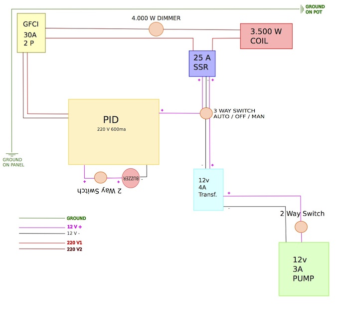
Attaching lay out...
In the heating element, were its written 3.500W please consider as 3.200w.
I don`t need to use 110V in this simple panel, but in all other lay-outs that i saw here in HBT they use the neutral line.
Thanks again (and sorry about any mistakes in my writing)

ELECTRIC LAYOUT.jpg


View attachment ELECTRIC LAYOUT.pdf
 
Does your PID power the buzzer directly or is it a relay output? What is the input rating on the buzzer? Also you may know this already but if you haven't checked you may want to verify whether your 12v pump is a/c or DC. If it's DC you'll need a rectifier after your 12v transformer.
 
Floormatg,
The PID power the buzzer directly with 220v output.
The buzzer is 220v 20ma. And the transformer for the pump is rectified.
Best regards.
 
Keep in mind your 12V @ 4 amps is very low current at 220V AC so you have some extra margin.
Your PID current also seams high.

I would add a contactor and an on/off switch or estop that can kill 220v power to your panel. You should be able to find one w/ a 220v coil or 12v coil.
 
Floormatg,
The PID power the buzzer directly with 220v output.
The buzzer is 220v 20ma. And the transformer for the pump is rectified.
Best regards.

I would double check you PID does power the buzzer internally. Most of the ones I have seen have relay contacts for the alarm outputs. Do you have a model number?
 
Mattd2
My PID is a Rex-C700.
The manual is in this link: http://www.rkcinst.com/english/pdf_manual/imnzc18e3.pdf .
Thanks.

Yep, the alarm outputs (ALM1 & ALM2) are relays. Common on 8 (220VAC to this terminal) and ALM1 on 9 and ALM2 on 10.

It would also seem that the alarm types are set at factory on the REX-C***, check the full model number against section 1 to confirm what type of alarms you have.
Or if you can post it here I can help, it should look something like:
REX-C700-???-??*??, where the "?" are diffenet numbers/letters
 
I received it last monday and it was still packed (Shame on me!) untill now
REX-C700-FK02-M*AN
Output: RELAY
ImageUploadedByHome Brew1389310307.200104.jpgImageUploadedByHome Brew1389310346.018630.jpg
 
Friends,
The great concern is the limited power supply of my outlet in 20A.
I have a few equipments like contactors, signaling lights, buzzer, and other stuff in 110V, as i was planning to make as a P-J design BUT i didn't check the power output issue (stupid!).
So i had to make a lay-out limited to my conditions... That's why I asked for help.

The buzzer is just a cosmetic touch and can be removed from the lay-out without any problem.

I follow the KISS method, but the contactor / E-stop is a real good and safe idea.
Thanks
 
Yep, so you only have one alarm - ALM1. And it is a Deviation alarm = if the process value increase the amount over (-ve value for under) the Set value the alarm with trigger.

Running through your spec:
F - Heating mode only with Autotune
K02 - you can only use a 0-400°C K type thermocouple sensor
M - Relay contact (this will not directly drive a SSR input)
A - As above
N - No ALM2

In all honesty I don't think this is the best PID for you. Sorry.
The best options normally used on HBT are:
Auber - good documentation fully functioning controller - Usually the SYL-2352
MyPin - Just starting to see this brand, seems similar functionality to the Auber. but someone else will need to chip in (Alien or Audiophile) but I have had not dealt with them before. Get the TD4 as it has manual control (apparently) Documentation is seems very minimal!
Sestos - Similar to Auber but only °C, documentation limited and can be hard to understand due to translation
 
Friends,
The great concern is the limited power supply of my outlet in 20A.
I have a few equipments like contactors, signaling lights, buzzer, and other stuff in 110V, as i was planning to make as a P-J design BUT i didn't check the power output issue (stupid!).
So i had to make a lay-out limited to my conditions... That's why I asked for help.

The buzzer is just a cosmetic touch and can be removed from the lay-out without any problem.

I follow the KISS method, but the contactor / E-stop is a real good and safe idea.
Thanks

So have you already purchased items that are rated for 110VAC.
If so you have 2 choices:
1) Try and exchange your 110VAC equipment for 220VAC equipment (or bit the bullet and buy new 220VAC quipment), or
2) Purchase a 220VAC to 110VAC transformer that is rated for the expected current of the 110VAC equipment. I would expect the current draw to be minimal so just add up all the currents of the indicators/buzzers/etc.

In terms of what your outlet can supply you have 220V * 20A = 4400W. Your heating element is using 3200W, so you have 4400W-3200W = 1200W for the rest of you equipment before you hit 20A.
Add up the watts that the remainding gear uses and I would guess you would be way under 1200W!
 
Yep, so you only have one alarm - ALM1. And it is a Deviation alarm = if the process value increase the amount over (-ve value for under) the Set value the alarm with trigger.

So I can remove the buzzer and problem solved.

Running through your spec:

F - Heating mode only with Autotune

K02 - you can only use a 0-400°C K type thermocouple sensor

M - Relay contact (this will not directly drive a SSR input)

I have 2 K thermocouples (short and medium). This won't be an issue.
As the PID didn't drive the SSR, I thought wiring the 12v transformer in the PID RELAY output port. So the transformer will drive the SSR when in manual mode and in auto mode it will provide power when the PID trigger it.
Wright?

In all honesty I don't think this is the best PID for you.

Neither do I, as you made me saw that the PiD is wrong. Thanks.

Sestos - Similar to Auber but only °C, documentation limited and can be hard to understand due to translation


I'm from Brazil and Celsius is the standard here. That's why my english is not so good.

Thanks again.
 
So have you already purchased items that are rated for 110VAC.

If so you have 2 choices:

1) Try and exchange your 110VAC equipment for 220VAC equipment (or bit the bullet and buy new 220VAC quipment), or

2) Purchase a 220VAC to 110VAC transformer that is rated for the expected current of the 110VAC equipment. I would expect the current draw to be minimal so just add up all the currents of the indicators/buzzers/etc.

This won't be a problem. I have 2 keggles and pretend to build both. So I can sell the second unit and recover money.


In terms of what your outlet can supply you have 220V * 20A = 4400W. Your heating element is using 3200W, so you have 4400W-3200W = 1200W for the rest of you equipment before you hit 20A.

Add up the watts that the remainding gear uses and I would guess you would be way under 1200W!

I considered 15.9A (3.500w) for the element, 3A for the pump and the other 1.1A for the signaling lights, buzzer and PID.
But how should i consider the 3A from the pump?
 
...As the PID didn't drive the SSR, I thought wiring the 12v transformer in the PID RELAY output port. So the transformer will drive the SSR when in manual mode and in auto mode it will provide power when the PID trigger it.
Wright?
Sounds good, Note that they recommend a control period of 20 seconds for the relay output models, but I would expect this was for 24/7 operation. Since for homebrewing we only use these for a few hours every so often I think you could still go down to 2 seconds control period (I think I calculated it out once and you'd still get 10+ years operation brewing once every week)
Neither do I, as you made me saw that the PiD is wrong. Thanks.

I'm from Brazil and Celsius is the standard here. That's why my english is not so good.

Thanks again.

As it should be the world over! :D
 
...I considered 15.9A (3.500w) for the element, 3A for the pump and the other 1.1A for the signaling lights, buzzer and PID.
But how should i consider the 3A from the pump?

Since you are dealing with different voltages you need to look at it a bit differently than straigh amps. Power = volatge * current. Simply looking at it (ignoring the losses from stepping down the voltage trhough the 12V power supply) you have:
Total power available = 220V * 20A = 4400W

Element = 3500W
Pump = 12V * 3A = 36W
PID = 9W (from the datasheet)
Indicators = lets say 3W each and you have 20 = 60W

Total Power - 3500 + 36 + 9 + 60 = 3605W
Current - 3605W / 220V = 16.4A
All good as you are way under 20A
 
Since you are dealing with different voltages you need to look at it a bit differently than straigh amps. Power = volatge * current. Simply looking at it (ignoring the losses from stepping down the voltage trhough the 12V power supply) you have:

Total power available = 220V * 20A = 4400W


Element = 3500W

Pump = 12V * 3A = 36W

PID = 9W (from the datasheet)

Indicators = lets say 3W each and you have 20 = 60W


Total Power - 3500 + 36 + 9 + 60 = 3605W

Current - 3605W / 220V = 16.4A

All good as you are way under 20A


Now i understand how this works.
I have a verry basic knowledge of electrical design and assembly and cannot express how grateful I am for your and other members help.
I'll post tomorrow the new setup with this changes.
Thanks again.
 
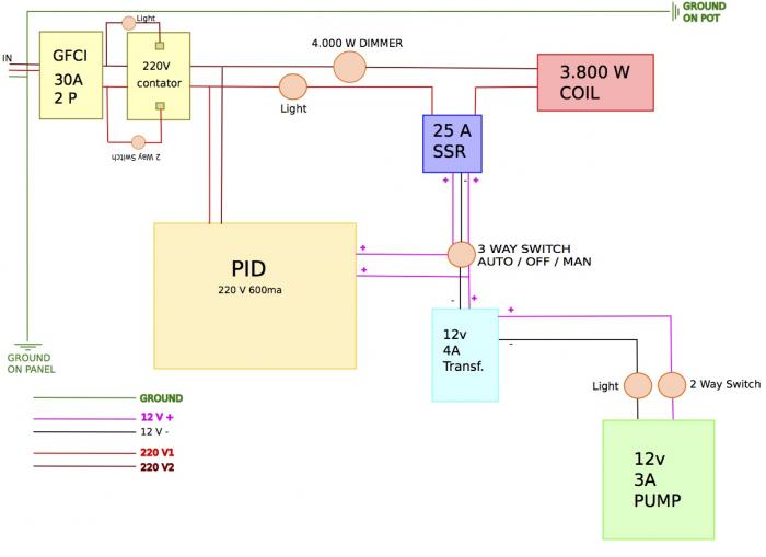
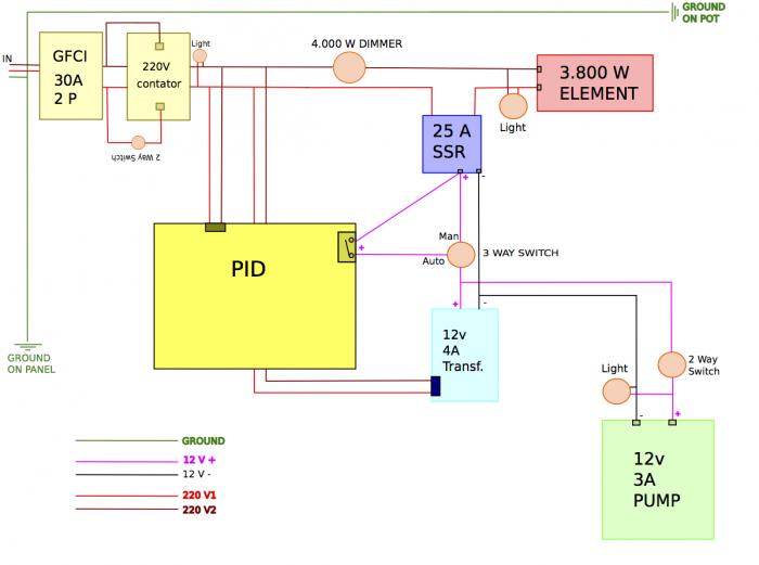
Here`s the new lay-out - No buzzer, but with added safety and lights. The lights are designed "in series", but i already know that they must be connected "in paralel". Thanks.

NEW ELECTRIC LAYOUT.jpg
 
When I built my electric rig I was in a similar situation. I had a 40A 240V circuit without neutral but a ground. I wired my GFCI power from the 240V circuit so the two "hot" legs came from the 240. I also had another power cord coming into my panel from an extension cord that fed a 120 circuit to all other components. It also fed the neutral and ground to the GFCI circuit.

This will give you three advantages over a circuit that provides you all four legs with one outlet.

  1. I rent and have to move often for the nature of my job. On my last move the type of outlet I had available to me changed. I just wired on a different plug making sure my two 120 legs were being provided to my GFCI and the rest of my power needs was provided from a normal 120 circuit.
  2. I use a contactor switch to fully turn off the power to my 240 legs. Since the power for this circuit comes from the 120 outlet. I am able to put a simple cheap wall timer on this leg and have it go on whenever I want. So I can set it for 645 in the morning and set my alarm clock to 730 and wake up to a fully heated kettle and can be ready to mash the moment you get out of bed.
  3. In the case of your limited amount of power available on the 220V circuit. Having a separate 110 circuit allows your misc electrical needs run off a separate line and allowing all your 220 to be used just for heating water or wort.
 
If you have 30amp power available (not 20amp) than use a 4500W or 5500W heating element.

I suspect you will trouble boiling 10gal with <4k watts. You will probably need to insulate your kettle, etc.
 
If you have 30amp power available (not 20amp) than use a 4500W or 5500W heating element.

I suspect you will trouble boiling 10gal with <4k watts. You will probably need to insulate your kettle, etc.

He could still go 4500W on a 20A circuit - current draw is only 18.75A for a 4500W / 240VAC element.
 
Paulillo,
I have a few questions about your diagram since it appears to answer a question I have had regarding my own build - although mine will not be exactly like yours.

171933d1389627508-i-need-some-help-my-panel-single-vessel-220v-no-neutral-limited-power-input-new-electric-layout.jpg


1. Which PID are you using? You mentioned 220V PID. I will be doing a 220V build, and the PID I'm considering is powered by one of the 110V legs. I understand why you can't do that without a neutral.

2. I assume that the 2 vertical wires attached to the top of your PID (lefthand pair) are providing the 220V power to your PID.

3. Regarding the 2nd pair of wires that "appears" to be attached to your PID: is this simply an illusion? Does this pair go "around" your PID (you just couldn't draw it that way) in order to supply power to your 220VAC/12VDC transformer?

4. Which dimmer is attached to the other hot line? In my build, this would be a SSVR (looks like a SSR except it includes a potentiometer that allows it to control the amount of power going to the element).

I understand that this "dimmer" will allow you to adjust your boil when you're in either MANUAL mode or AUTO mode much like High Gravity's EBC-SV controller.

5. Really, your 3-way DC switch (Auto/Off/Manual) is the solution that I was agonizing over in my build (which did not include a transformer).

In your AUTO mode, the SSR receives its DC signal from the PID. You're still able to control the power with your dimmer.

In your AUTO mode, the DC signal circuit from the PID to the SSR is interrupted, and your SSR receives a constant ON signal from the transformer.

Am I understanding this correctly?

Thank you for posting this,
Keith
 
If you have 30amp power available (not 20amp) than use a 4500W or 5500W heating element.

I suspect you will trouble boiling 10gal with <4k watts. You will probably need to insulate your kettle, etc.

JCOSbrew, I have only 20A available in the outlet.
The GFCI is rated 30A and i will use it just for protection.
B.Regards
 
Paulillo,
I have a few questions about your diagram since it appears to answer a question I have had regarding my own build - although mine will not be exactly like yours.

1. Which PID are you using? You mentioned 220V PID. I will be doing a 220V build, and the PID I'm considering is powered by one of the 110V legs. I understand why you can't do that without a neutral.

The PID is a REX C700. It can be powered by 220, 110 and even 24v. Not the best PID for this application but will work. Check some pictures on page 2 of this thread.

I can't use the neutral because my outlet only delivers 220 (110 + 110) and Ground on 20A.

2. I assume that the 2 vertical wires attached to the top of your PID (lefthand pair) are providing the 220V power to your PID.

3. Regarding the 2nd pair of wires that "appears" to be attached to your PID: is this simply an illusion? Does this pair go "around" your PID (you just couldn't draw it that way) in order to supply power to your 220VAC/12VDC transformer?

The lefthand wires are connected to the PID and the righthand are connected to the pump. In my previous lay out the 220v that connects to the pump was not shown and i received a few questions on how it is powered, so i draw them.
All power inputs are designed like "darker squares" (resembling connectors) in the components.
This design also is a visual guidance for me to assemble my box, were the PID, lights and switches will be attached on the door and the contator, SSr and transformer will be on the bottom of the box. Sorry if it looks a bit confused.

4. Which dimmer is attached to the other hot line? In my build, this would be a SSVR (looks like a SSR except it includes a potentiometer that allows it to control the amount of power going to the element).

I understand that this "dimmer" will allow you to adjust your boil when you're in either MANUAL mode or AUTO mode much like High Gravity's EBC-SV controller.

This "dimmer" is a SCR voltage regulator and you`re wright, this allows me to adjust the heating amount of my element in all the variants in the brew day (boiling, heath keeping, slow warming, etc).
It`s like this:
http://www.aliexpress.com/item/4000...eed-Control-Thermostat-Dimmer/1154827239.html

5. Really, your 3-way DC switch (Auto/Off/Manual) is the solution that I was agonizing over in my build (which did not include a transformer).

In your AUTO mode, the SSR receives its DC signal from the PID. You're still able to control the power with your dimmer.

In your AUTO mode, the DC signal circuit from the PID to the SSR is interrupted, and your SSR receives a constant ON signal from the transformer.
Am I understanding this correctly?
Thank you for posting this,
Keith

Just a small correction:
In your MANUAL mode, the DC signal circuit from the PID to the SSR is interrupted, and your SSR receives a constant ON signal from the transformer.

The element power can be controlled in any situation (auto or manual).
The PID has RELAYS as outputs, so it can trigger the dc signal AUTO mode, and in MANUAL mode the dc signal is constant. In OFF mode, no signal is released.
For your guidance, the 3-way switch is wired like this:
http://cdn.homebrewtalk.com/attachments/f51/17411d1285885259-bcs-460-wiring-off-auto3.jpg

I hope that this can help you.
Thanks
 
Thank you, Paulillo, for your response. I was having trouble figuring out your correction in my question, then I realized that I had typed "AUTO" twice. Of course, it was "MANUAL" mode that I meant in the 2nd instance.

I will have neutral available in my build, so mine will be different from yours, but your has answered a question or two for me that I will be able to adapt to mine. Thanks for posting.
Keith
 
Back
Top