• Please visit and share your knowledge at our sister communities:
  • If you have not, please join our official Homebrewing Facebook Group!

    Homebrewing Facebook Group

HOWTO - Make a BrewPi Fermentation Controller For Cheap

Homebrew Talk

Help Support Homebrew Talk:

This site may earn a commission from merchant affiliate links, including eBay, Amazon, and others.
Status
Not open for further replies.
I'm using the Sainsmart relay card from the original post. The BrewPi runs flawlessly and the web interface is all you need, but darn it if it isn't cool to have the LCD screen on the box. My ten year old discovered the scramble. He told me that the screen changed to Chinese.
I've found that the refrigerators compressor can spike the display when it switches on and off, to address that I soldered a 100Uf capacitor on the power input to filter that out. which solved that issue. But I still get occasional display issues I can't explain, such as characters where there should be none, but its not as bad. To deal with that I just installed a reset switch on the side of the case and wired it to the reset pin on the uno and gnd. Now if the display is dirty, I just press that and go on with life.
There is a lot of information about displays in this thread https://www.homebrewtalk.com/showthread.php?t=510036
 
So, I wired up everything exactly like the schematic...resistor and everything. The brewpi finds 4 devices, but it doesn't find the A4 (OneWire) sensor probes. They have another pin listed.
 
I've found that the refrigerators compressor can spike the display when it switches on and off, to address that I soldered a 100Uf capacitor on the power input to filter that out. which solved that issue. But I still get occasional display issues I can't explain, such as characters where there should be none, but its not as bad. To deal with that I just installed a reset switch on the side of the case and wired it to the reset pin on the uno and gnd. Now if the display is dirty, I just press that and go on with life.
There is a lot of information about displays in this thread https://www.homebrewtalk.com/showthread.php?t=510036

You soldered the cap to the power input on the relay board?
 
So, I wired up everything exactly like the schematic...resistor and everything. The brewpi finds 4 devices, but it doesn't find the A4 (OneWire) sensor probes. They have another pin listed.

Note...I've checked to make sure that the sensors are the right type. Everything seems to be wired correctly. Interestingly enough, I got an A5 pin designation, but nothing plugged in there. Then, I tried changing the pin what would be A3 (thinking it might read A4), but still got an A5 pin location.
 
You soldered the cap to the power input on the relay board?

Yes, it's an electrolytic cap, so you have to mind polarity. Just identify the solder pads for the center pin (+) and the outer barrel (-) solder the cap to those pads.
 
Note...I've checked to make sure that the sensors are the right type. Everything seems to be wired correctly. Interestingly enough, I got an A5 pin designation, but nothing plugged in there. Then, I tried changing the pin what would be A3 (thinking it might read A4), but still got an A5 pin location.


You are seeing the arbitrary hard coded devices and not the detected devices. only one wire devices show up as detected devices. what you are seeing is a5 a hard coded control pin for the brewpi. if you either don't have your one-wire devices wired correctly or you didn't use the proper resistor for the onewire to function. Or you didn't hit the scan for devices button.
 
Yes, it's an electrolytic cap, so you have to mind polarity. Just identify the solder pads for the center pin (+) and the outer barrel (-) solder the cap to those pads.
Where do i solder the caps?
385a02153c87b62cc59d568f9f8ecacbf800cb33.png
 
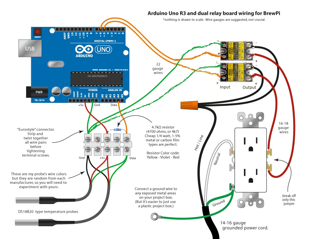
Like Brewski mentioned I had the issues with spikes on my graph with interference from the compressor turning on with the saismart mechanical relay. Elco said to switch to SSR relays and the spikes should go away. I ordered two of the SSR relays he suggests and will be hooking them up like this.

I will post my findings once they are hooked up and arrive.

ARDUINO.jpg
 
Yes ssrs would probably fix it if the lcd means a lot to you, they are just a lot more expensive than the cheap mechanical relays which are quite electrically noisy in comparison.
 
Well, the electromagnetic interference that may garble the LCD is caused by that the relays are not synced to the frequency used(120V/60Hz for you US guys) so when the circuit is altered it may cause a lot of induction. Scrambling may be even worse with 230/50Hz (used here across the Atlantic). A solid state relay will always switch the circuit when it is low, see: http://www.allaboutcircuits.com/textbook/digital/chpt-5/solid-state-relays/

The mechanical relays are with out a doubt (at least for me) the cause of LCD garbage as I have had one of my BrewPi minions set to off (hence not any chance to switch on or off) for weeks, and everything was steady as a rock. A way to fix this would be to somehow make the relays aware of the frequency and tune the switching accordingly, but its easier to just just use SSR:s instead. (Or use the reset of LCD patched AVR program as I have).

- I thought I would have time to test the new legacy branch Elcoe have gracefully provided, but I have tinkered too much with the code (by using a I2C LCD module etc.) and my setup does its job admirably, so I would have to mess with the working configuration as I have put all of them in production.

Regards and good luck /A
 
You are seeing the arbitrary hard coded devices and not the detected devices. only one wire devices show up as detected devices. what you are seeing is a5 a hard coded control pin for the brewpi. if you either don't have your one-wire devices wired correctly or you didn't use the proper resistor for the onewire to function. Or you didn't hit the scan for devices button.

I have no clue...VCC, DATA and GRND are all wired correctly. The resistor between VCC and DATA is 4.7 kOhm and the sensors are DS18B20 sensors. The only thing I can think of is the wire going to A4 could be faulty. Otherwise, I am at a loss.
 
I have no clue...VCC, DATA and GRND are all wired correctly. The resistor between VCC and DATA is 4.7 kOhm and the sensors are DS18B20 sensors. The only thing I can think of is the wire going to A4 could be faulty. Otherwise, I am at a loss.

So...I wired two new sensors, a new resistor, and a new wire coming from the A4 pin female...still nothing. My devices listed are Pin 2 (Act 3), Pin 5 (Act 2), Pin 6 (Act 1), Pin A5 (Act 4), and Pin 4 (Door). Next to do is to get my multimeter and check output of 5V and ground.

Ran multimeter from 5V output to grounds on the Arduino, etc., and got 4.99 VDC. That's as close as it gets in my world.

Not sure what is going on...any help would be mucho appreciated.
 
So...I wired two new sensors, a new resistor, and a new wire coming from the A4 pin female...still nothing. My devices listed are Pin 2 (Act 3), Pin 5 (Act 2), Pin 6 (Act 1), Pin A5 (Act 4), and Pin 4 (Door). Next to do is to get my multimeter and check output of 5V and ground.

Any help would be mucho appreciated.

BrewPi will show a bunch of devices by default even if there is nothing there.
So a few pages back I was having the same issue and narrowed it down as best I could to the arduino board so I sent it back for a replacement. I got it yesterday and this morning I simply wired it in after loading the HEX file separately, and all my devices showed up.
One thing I found out after I sent back my board is that maybe the bootloader on the arduino needed to be reinstalled/repaired which you can learn about here installing-an-arduino-bootloader
how-to-flash-arduino-bootloader-without-a-programmer/
 
Last edited:
I'm still waiting for an answer as to if you refreshed the detected devices list or if you just clicked devices, saw the hard coded devices and thought, "no temp probes"
 
I'm still waiting for an answer as to if you refreshed the detected devices list or if you just clicked devices, saw the hard coded devices and thought, "no temp probes"

I guess going through and wiring all that twice without pressing "Refresh devices list" has been done, but I did that about 10 times...with and without "Read Values" checked. This is what was returned...

No installed devices found
Parsing available devices
Device list updated for uno with a revC shield

That keeps getting spit back.
 
So I wired mine up plugged it in and I don't get the led light to light up on the uno. Leading me to believe it's not getting power I can't figure where I went wrong. The power chord fell off the counter and the weight of it pulled my relay board into the outlet and there was a pop. It wasn't working before this but I'm hoping someone can look at my wiring and see where I went wrong or if I am gonna need a new relay even though everything wasn't working before. Please help I tried to make it look like the schematic cause I have zero electrical experience..

View attachment ImageUploadedByHome Brew1462060971.994140.jpgView attachment ImageUploadedByHome Brew1462060985.397061.jpgView attachment ImageUploadedByHome Brew1462060999.931851.jpgView attachment ImageUploadedByHome Brew1462061048.049330.jpg
 
Well, I can't see the terminals perfectly, but it looks like your quite possibly relaying your hot lead directly to ground… not looking good.

Yeah I looked a little harder. your receptacle is wired up completely wrong, your relays are completely fried , you are lucky to be alive.

****NOTICE****

There may be over 500 pages of useful information in this thread, and some things may get taken for granted. it should be noted, that this project requires adequate knowledge into the inner workings of how live mains current flows and how to use and wire properly, mains current applications. these voltages can be FATAL if you come into contact with live wires, or if you mis-wire or short out something. while it has been noted in the op that you take on this project at your own risk, please understand that if you do not know how to properly wire a receptacle or standard wall switch, you should contact a certified professional before attempting this project.
 
The Arduino gets power from the Pi via the USB connection. If you powered things up without a Pi the Uno won't light up.

Secondly, are you using conventional wiring colours? Normally green is ground, but you are using it for the relay supply. If you are using green for ground it should not be connected to the relay.

Finally you should be extremely careful powering up the circuit with no enclosure or safety precautions (do you have a fuse?). If wires touch accidentally you could destroy any piece of the assembly.

Double check your wiring against the diagram. Put it in an enclosure (even a temporary one) to protect yourself from shock during testing. And don't be tempted to poke around while it's powered up. You can also tape the feed cable to the desk to stop it pulling on the assembly.
 
Well, I can't see the terminals perfectly, but it looks like your quite possibly relaying your hot lead directly to ground… not looking good.

Yeah I looked a little harder. your receptacle is wired up completely wrong, your relays are completely fried , you are lucky to be alive.

****NOTICE****

There may be over 500 pages of useful information in this thread, and some things may get taken for granted. it should be noted, that this project requires adequate knowledge into the inner workings of how live mains current flows and how to use and wire properly, mains current applications. these voltages can be FATAL if you come into contact with live wires, or if you mis-wire or short out something. while it has been noted in the op that you take on this project at your own risk, please understand that if you do not know how to properly wire a receptacle or standard wall switch, you should contact a certified professional before attempting this project.


The Arduino gets power from the Pi via the USB connection. If you powered things up without a Pi the Uno won't light up.

Secondly, are you using conventional wiring colours? Normally green is ground, but you are using it for the relay supply. If you are using green for ground it should not be connected to the relay.

Finally you should be extremely careful powering up the circuit with no enclosure or safety precautions (do you have a fuse?). If wires touch accidentally you could destroy any piece of the assembly.

Double check your wiring against the diagram. Put it in an enclosure (even a temporary one) to protect yourself from shock during testing. And don't be tempted to poke around while it's powered up. You can also tape the feed cable to the desk to stop it pulling on the assembly.


The hot leads aren't going directly to ground I just tore apart a computer chord and used the wires in there they had a green blue and a brown I thought brown was more often used as a ground color but either way I used the green as the hot side. I did have it in the project box the first time I plugged it in I just got careless the second time and taping the chord down is a good idea cause that definitely got. My attention I had it all sitting on the plastic lid of the box as a buffer. If the chord hadn't fell off the counter and drug the stuff with it I wouldnt have gotten the short. Okay I thought the uno got the power from the wiring I will have to plug it into my pi I just didn't wanna go to the next step if all wasn't working. Do the relays definitely need to be replaced before I move on? I did plug the uno into the pi via usb just to see if that powered it I hadnt set up or programmed the pi yet and it didn't light up the uno not sure if that step has to be done first. I thought the thing was able to run independently of the pi in case of a pi crash I guess that's why I thought it got its power differently.
 
If the Pi crashes it will still provide power to its USB port, which will continue to power the Arduino, so it will still run. Alternatively, you can use a separate low-voltage power supply into the barrel connector on the Arduino and power it independently of the Pi.

I don't know if you have destroyed something, or what you have destroyed, but "getting careless" is a sure-fire way to kill or injure yourself. You must be more careful.

For future reference, the colour conventions for that particular set of colours is:
Brown - live (or "hot")
Blue - neutral
Green (or green and yellow) - ground

It is very hard to diagnose and troubleshoot stuff like this over the Internet. Try and find someone nearby with experience who can check things out and advise you. Even consider paying an electrician to check it.


Yeah thanks for the help I definitely am weary of electricity and did everything unplugged I just need to be even more careful with the possibilities I didn't think about like the chord being taped down. Yeah I should change the colors just to make it easier to fix or diagnose all though I didn't cross them cause I wired them to the female plug just used the wrong colors as I used a green wire on the hot post. I plugged everything exactly wire to wire from the diagram. I am installing my pi software now so we will see if that powers it up the uno now. I'll probably replace the relay if nothing else as a precaution.
 
I've read about 120 pages and ... well I think my question is so basic that it's just not covered:

Is the web server (Either RaspberryPi or PC) there to initially control and then monitor? In other words once your setup is running, can you unplug the USB port (assuming you have power otherwise supplied to the Arduino) and it still runs?

Obviously you lose monitoring; you also lose historical information I assume?
 
Yup. The temperature control lives on the Arduino.

If you have an LCD and rotary encoder connected to the Arduino you can set up the BrewPi locally, no Pi required (and no data logging or web interface, of course).
 
So I wired mine up plugged it in and I don't get the led light to light up on the uno. Leading me to believe it's not getting power I can't figure where I went wrong. The power chord fell off the counter and the weight of it pulled my relay board into the outlet and there was a pop. It wasn't working before this but I'm hoping someone can look at my wiring and see where I went wrong or if I am gonna need a new relay even though everything wasn't working before. Please help I tried to make it look like the schematic cause I have zero electrical experience..

View attachment 352518View attachment 352519View attachment 352520View attachment 352521
Its obvious from these photos you don't understand how a relay works. Think of it as a switch. the center terminal marked C is common. The terminal marked NC is normally closed, it is connected to common in an off state. the one marked NO is normally open it is not connected to common in an off state but switches to be connected to common in an on state. Therefore only connect one wire color to any of these three terminals. Normally were working with black (hot) White (neutral) and green (gnd) the black wire is what you connect to the relay. Take the wire from your power source to the C terminal and switched output that you want to control to the NO terminal. What I see in your photo is you have connected ground to the C terminal, and power to the NC or NO terminal. This will result in a direct short to ground causing that burned trace evident in the photo of the back side. Chances are you've destroyed that relay board. I suggest you do a little more research and have a better understanding of electricity before you continue, or get a friend who does have this understanding to help you out.
 
Its obvious from these photos you don't understand how a relay works. Think of it as a switch. the center terminal marked C is common. The terminal marked NC is normally closed, it is connected to common in an off state. the one marked NO is normally open it is not connected to common in an off state but switches to be connected to common in an on state. Therefore only connect one wire color to any of these three terminals. Normally were working with black (hot) White (neutral) and green (gnd) the black wire is what you connect to the relay. Take the wire from your power source to the C terminal and switched output that you want to control to the NO terminal. What I see in your photo is you have connected ground to the C terminal, and power to the NC or NO terminal. This will result in a direct short to ground causing that burned trace evident in the photo of the back side. Chances are you've destroyed that relay board. I suggest you do a little more research and have a better understanding of electricity before you continue, or get a friend who does have this understanding to help you out.


Yeah I mean I'm sure there's a lot I don't understand but as I understand it a relay is an electrically actuated switch. I have my wires wired up to a quick connect power inlet like this http://www.amazon.com/dp/B00917Z96S/?tag=skimlinks_replacement-20 I just was scrapping wire and didn't use sensible colors on the inside which i see is a mistake because it makes it more confusing. But nothing is crossed I just used a green colored wire from the hot side to the innards so with the relay I have the hot line going to the wire nut and going to two more wires one connected to the one (common port) and the other to the other common port. Then I have a line going from each normally open port on the relay to the hot side of the outlet with the jumper broken open. The short didn't occur until the relay circuit board Got pulled into the outlet and they touched. Which I'm assuming is what caused the short. So I'm believing the wiring was correct other than just using non sensible colors. That being said I haven't plugged it in since and I plan on replacing the lines with the correct color codes to make it not confusing in case I have to ever troubleshoot it again.

The uno and pi have been programmed and it finds my temperature probe and the relay. Which leads me to my next question is there anything dangerous about replugging this thing in to see if the relay still works and my outlets obviously properly grounded in the project box before I test this or should I just replace the relay first. Guess I'm just not sure if it is destroyed if it's going to become a bunch of flying sparks or if it just will be dead I dont want to do anything dangerous if replacing it is the safest option I don't mind spending the money on a new one.
 
Last edited by a moderator:
After reviewing the photo, now I see how its wired. Changing color threw me, and a few others off. We're trained to keep green ground, so it looks lIke you've made a terrible mistake. But no, you've just changed color mid run. Sorry for overreacting.
 
Do you have an ohm meter? It's easy to check a relay with a meter. Or you could plug a light into your socket, and switch it on and off by toggling the relay on and off. Just change the pin type from inverted to non inverted in the device list and the relay will change state.
Do yourself a favor, use some tape to cover those solder pads on the back of the board where the arc burn is. It's pretty easy to accidently touch those when handling the board. That will get your attention real quick.


Yeah thanks for all the help when I get back from my trip I'll tape it up and try your method of testing the relay. I had the outlet taped but taping the bottom of the board also seems like a good precaution. I still feel like fixing the wire colors could be a good and safe thing to do so as not throw me off in the future if I have to make repairs. Plus if somethings worth doing it's worth doing right. I guess I just got focused on making sure I connected the right wires to the right Parts that I just kinda used any color of connectors without thinking twice . But all the help and criticism is welcome and I'm always excited to learn new things. I'm Glad to know that after closer inspection everything looks to be wired correctly in the future I'll tape all my circuit boards and tape the chord down before plugging it in to make sure it works.
 
Do you have an ohm meter? It's easy to check a relay with a meter. Or you could plug a light into your socket, and switch it on and off by toggling the relay on and off. Just change the pin type from inverted to non inverted in the device list and the relay will change state.
Do yourself a favor, use some tape to cover those solder pads on the back of the board where the arc burn is. It's pretty easy to accidently touch those when handling the board. That will get your attention real quick.


Oh and no ohm meter I'll just have to test the outlet with a light or something
 
And just so we're all perfectly clears. Brewpi cannot sense or find a relay. it's a hard coded device built into the software itself. it's going to show up whether you have it connected or not. 10 Times a day in this thread I see "it detected the relay but not the temp probes…". No no it does not "detect" your relay. your relay is merely there the software allows for it. seeing a relay under devices does not mean anything other than you were able to properly install the software.
 
And just so we're all perfectly clears. Brewpi cannot sense or find a relay. it's a hard coded device built into the software itself. it's going to show up whether you have it connected or not. 10 Times a day in this thread I see "it detected the relay but not the temp probes…". No no it does not "detect" your relay. your relay is merely there the software allows for it. seeing a relay under devices does not mean anything other than you were able to properly install the software.

So, for those of us that are not tech guys, how do you want us to relay what we see? Initially there isn't anything on the list. You have to ask it to "Refresh device list" before anything pops up. Then, we write down what we see. As far as we know the device "detected" those items.
 
So, for those of us that are not tech guys, how do you want us to relay what we see? Initially there isn't anything on the list. You have to ask it to "Refresh device list" before anything pops up. Then, we write down what we see. As far as we know the device "detected" those items.

Can you post a picture of your wiring? If you arent even seeing any A4 devices in the list then something is quite wrong.
 
Can you post a picture of your wiring? If you arent even seeing any A4 devices in the list then something is quite wrong.

For those who care, nebulous was right on the money. He didn't assume that we were idiots and couldn't follow directions. I'm not a computer hardware guru, but I know a few things and have wired complete houses, so the relay part made since from the beginning.

Anyway, the board and/or sensors were bad. I ordered a new board and new sensors. I reprogrammed the board from the web interface, wired everything back up to the board, checked the box marked "Read values" and clicked "Refresh device list." Guess what...the OneWire bus devices showed up first try.

Thanks nebulous. :mug:
 
Good to hear, there seems to be a batch of "bad" cheap knockoff Arduinos going around lately.
 
I have made it to the part where I am trying to reprogram the controller from the web interface. When I go through this it says that I need to install a new version of brewpi I think error 4 pops up as well. I have to my knowledge installed the newest version. The brewpi updater does not be able to program the controller. It pauses when it tries to open the serial port and says it can not determine the version. Im new at all of this and appreciate any help I can get. Thank you!
 
Good to hear, there seems to be a batch of "bad" cheap knockoff Arduinos going around lately.

I ordered the SainSmart one everyone said to get...not as cheap as some, but definitely not as expensive as the true Arduino board.

Also, I went to the calibrating probe page. That seems pretty crazy for the programming inept, but wondering if someone has written a program that will relatively calibrate the sensors based on ice water? Just curious.
 
It seems that on a daily basis someone comes here asking for help uploading the hex because the web interface isn't working. Has anyone tried Xloader, or put together alternative instructions? I feel like we could use a more reliable method. With a few tweaks you can even compile and upload the avr code with the arduino IDE...
 
Status
Not open for further replies.

Latest posts

Back
Top