• Please visit and share your knowledge at our sister communities:
  • If you have not, please join our official Homebrewing Facebook Group!

    Homebrewing Facebook Group

HOWTO - Make a BrewPi Fermentation Controller For Cheap

Homebrew Talk

Help Support Homebrew Talk:

This site may earn a commission from merchant affiliate links, including eBay, Amazon, and others.
Status
Not open for further replies.
Or you could repurpose the ballast as a space heater! lol

Btw: when the app says it couldn't post your comment… its lying just hit discard and reload.

There is definitely an issue with the ballast causing noise on the probes. I turned the light back on for awhile today and started losing graph data.

I still get random errors about the sensors being disconnected but it isn't as bad as when the light is on.

Also, thanks for the tip about the app. It's annoying. It tells me it couldn't post, sometimes it does and sometimes it doesn't and the I end up with double posts.
 
DCPCB is $25/10 ,you have a choice of soldermask color but takes almost a month for delivery.

Thanks - I'll keep that in mind - thats quite a bit better deal if a person can wait. Not sure how much OSH would be for 10 boards.
 
Osh only works in groups of 3, so it would be $75 for 9 boards. Another good option is pcbs.io; while I haven't used them yet, there pricing is good. $4/square inch for 4 boards. I'm going to give them a try on my next order.
 
Osh only works in groups of 3, so it would be $75 for 9 boards. Another good option is pcbs.io; while I haven't used them yet, there pricing is good. $4/square inch for 4 boards. I'm going to give them a try on my next order.

now that sucks... They were closer, faster, and cheaper...

Thanks for sharing!
 
I have used dirtyPCBs one time and the result was excellent. If you want the boards quicker you can pay more for faster delivery. It's probably not worth paying for faster manufacture (they turn the boards around in a few days), but standard shipping could take several weeks, so it's worth paying money there.
 
I've ordered recently from both OSH Park and DirtyPCBs. Both took about 3 weeks.

OSH Park was cheaper for very small boards ($5 sq. in. for 3 copies). My order was $3.10, shipping included, for 3 boards about 0.62 sq. in. each. Gold flashed pads, purple solder mask. Board edges were rough (perforated and snapped apart).

DirtyPCBs was cheaper for medium size boards ($25 < 10 x 10 cm, Protopack ±10 copies ). Tin plated pads, red solder mask (default... you can choose other colors) These boards were 3" x nearly 4" (and would have been $69 for 3 boards from OSH Park!) DirtyPCBs shipped 12 boards. Board edges were smoothly milled.

I was very happy with the quality of both orders.

Edit: On the ±10 thing... They say you will almost always get more than 10 boards, but you may get less... short 1 about 3% of the time, short 2 about 0.5% of the time... (If you absolutely have to be guaranteed 10 boards, it will cost more!)
 
Last edited:
One other place I would recommend is http://pcbs.io/

$4/sq. inch (or less) for 4 boards (shipped free globally), with gold flashed pads, black solder mask, etc. I've ordered from them 3 or 4 times now, and each time I've received more than 4 boards, but you're guaranteed at least 4.
 
Does anyone know which power socket I would use in the UK? Looking at the wiring diagrams, I'm not sure what the equivalent socket is (where the hot wire can be wired to the side).

Cheers - almost ready to build!!!
 
Does anyone know which power socket I would use in the UK? Looking at the wiring diagrams, I'm not sure what the equivalent socket is (where the hot wire can be wired to the side).

Cheers - almost ready to build!!!


I used two single plug sockets and wires them into a box as there isn't a metal tab to cut in the UK down to the way they're wired.

So take the power in and splice it to two sockets and wire each one up separately if that's makes any sense.

The earth and neutral, you wire directly to the plug sockets. And then the live comes separately from the SSRs or relays.

Is it possible to get a picture/diagram of that wiring? Is there a UK specific tutorial? I don't quite understand how you'd get the power to the two sockets, or wire then separately.
 
Is it possible to get a picture/diagram of that wiring? Is there a UK specific tutorial? I don't quite understand how you'd get the power to the two sockets, or wire then separately.


I'll take a pic of how I set mine up tomorrow. Or draw one at least it's very similar to the original drawing (and has worked for well over a year now) but I might not be the simplest method.
 
Is it possible to get a picture/diagram of that wiring? Is there a UK specific tutorial? I don't quite understand how you'd get the power to the two sockets, or wire then separately.


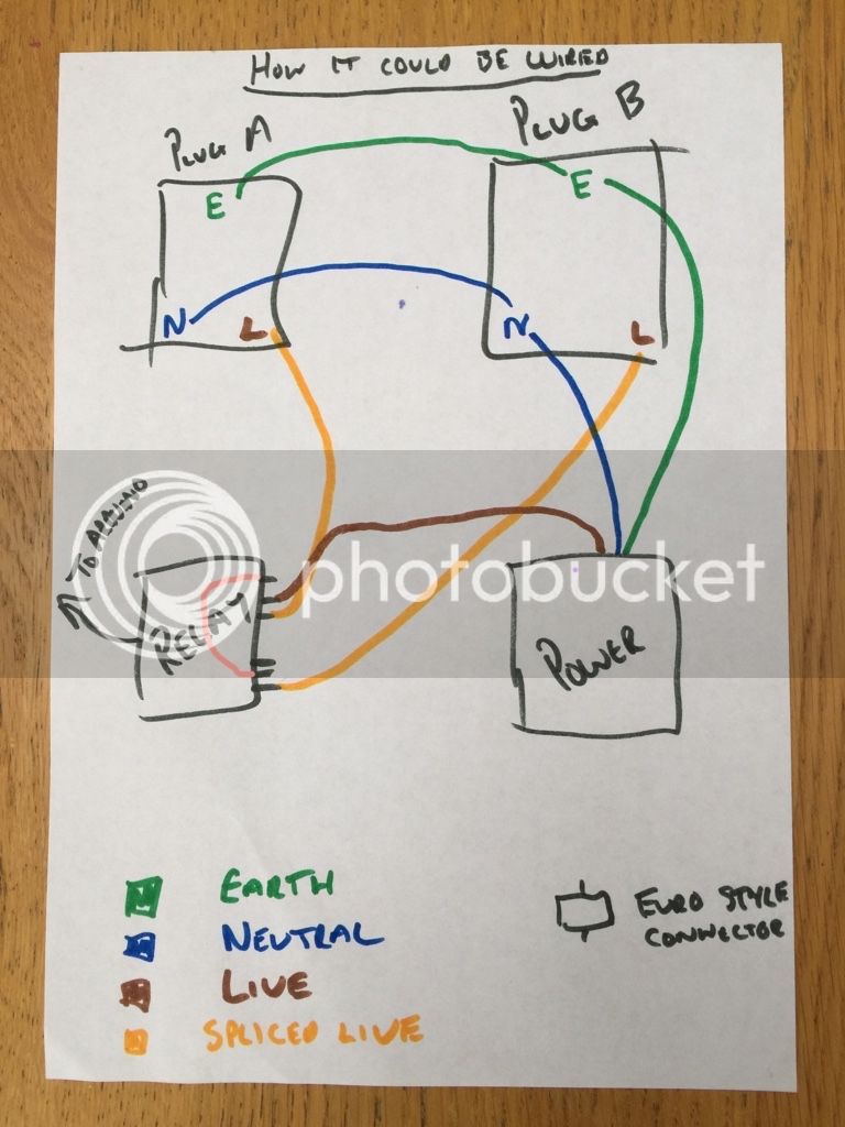
View attachment ImageUploadedByHome Brew1483136313.625296.jpgthe Uk version is very very similar.

The only difference being is that if you use two separate plugs (I suggest you do) is that you need to create the earth and neutral tab you seen in the attached picture.

You can do this by wiring.the earth and neutral to one plug, and then taking a spur from both the earth and neutral over to the second socket.

This isn't how I set mine up i used a Euro style connected to take feeds from the earth neutral and live and split them apart and thinking about it now i wouldn't do it this way.

But as mentioned I will take a photo of mine and post it tomorrow (it's not pretty but it works)
 
Really sorry about my crude drawings and photos Was in a rush and only had felt tips to use.

View attachment ImageUploadedByHome Brew1483188628.974069.jpg
View attachment ImageUploadedByHome Brew1483188652.011454.jpg
View attachment ImageUploadedByHome Brew1483188709.107367.jpg
View attachment ImageUploadedByHome Brew1483188722.619580.jpg
View attachment ImageUploadedByHome Brew1483188761.498020.jpg

Plug A and Plug B are the plug sockets and not plugs themselves.

I would get two single sockets and a double back panel B&Q is a good place to see the various options available I went cheap.

The power element is a computer power lead with the opposite end of the plug cut off. The longer the better for me anyway.

It's fairly straight forward and hopefully you can follow my diagrams. I'm not an electrician but I think the final drawing will work well.

There is also an option to completely avoid the need of the Euro style connector by running the live direct to the relay and then join the two middle relays pins.

In which case you'd ignore the brown lines in the picture below and use the pink one instead.

This should work and would mean that you could never accidentally heat and cool at the same time.

View attachment ImageUploadedByHome Brew1483189149.367880.jpg

Let me know if you need any further explanation or a better diagram and I'll try again.
 
Really sorry about my crude drawings and photos Was in a rush and only had felt tips to use.

View attachment 382577
View attachment 382578
View attachment 382579
View attachment 382580
View attachment 382581

Plug A and Plug B are the plug sockets and not plugs themselves.

I would get two single sockets and a double back panel B&Q is a good place to see the various options available I went cheap.

The power element is a computer power lead with the opposite end of the plug cut off. The longer the better for me anyway.

It's fairly straight forward and hopefully you can follow my diagrams. I'm not an electrician but I think the final drawing will work well.

There is also an option to completely avoid the need of the Euro style connector by running the live direct to the relay and then join the two middle relays pins.

In which case you'd ignore the brown lines in the picture below and use the pink one instead.

This should work and would mean that you could never accidentally heat and cool at the same time.

View attachment 382582

Let me know if you need any further explanation or a better diagram and I'll try again.

I think that's exactly what I need - thank you so much. I'll see how I get on with it - your diagrams have made it much clearer.

Cheers!
 
One other place I would recommend is http://pcbs.io/

$4/sq. inch (or less) for 4 boards (shipped free globally), with gold flashed pads, black solder mask, etc. I've ordered from them 3 or 4 times now, and each time I've received more than 4 boards, but you're guaranteed at least 4.

Thanks for that link! Looks good for small boards and/or fast turnarounds!
 
There is also an option to completely avoid the need of the Euro style connector by running the live direct to the relay and then join the two middle relays pins.
You can make that even cleaner - wire the second relay's hot leg from the NC side of the first relay. That way when the first relay is not energized the second relay has power. When the first relay is energized it breaks that and goes to it's NO pole.

Technically this is a better setup since it ensures there's no way to energize both at the same time.
 
You can make that even cleaner - wire the second relay's hot leg from the NC side of the first relay. That way when the first relay is not energized the second relay has power. When the first relay is energized it breaks that and goes to it's NO pole.


Technically this is a better setup since it ensures there's no way to energize both at the same time.


That'd be the pink line?
 
I think he means this:

Rewire.jpg
 
I think he means this:


Rewire.jpg


Actually not quite. I think the pink wire should go middle to middle on the relay.

Basically using the one live in to either heat or cool.

So when it's not heating the power is diverted to the cooling and vice versa.
 
Actually not quite. I think the pink wire should go middle to middle on the relay.

Basically using the one live in to either heat or cool.

So when it's not heating the power is diverted to the cooling and vice versa.

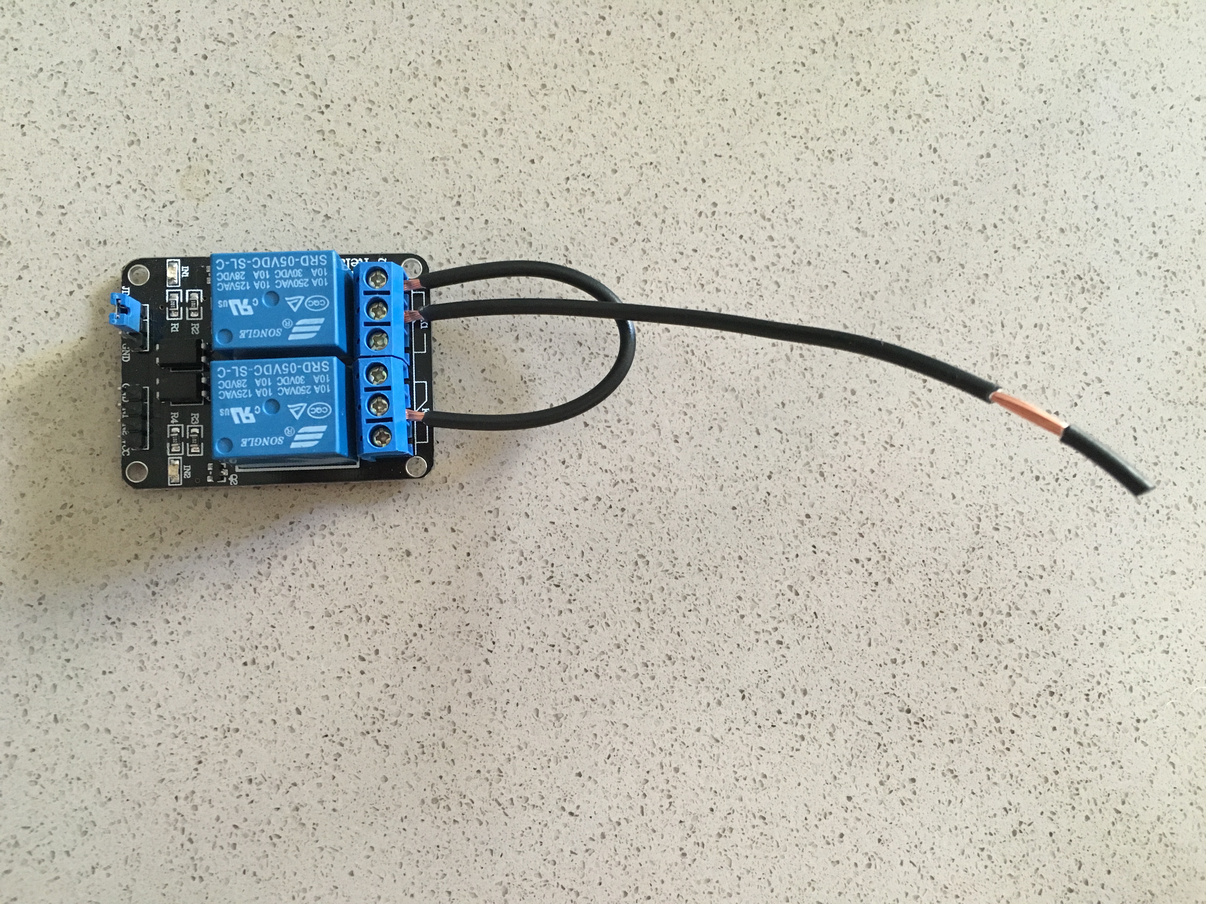
I think as drawn may be correct, in this case... Here's how I wired mine, with the free black wire going to mains power:

2016-11-12-09.14.21.jpg
 
That will work. just know that when the right relay is running the left relay has no power. Which is fine since we only use either heating or cooling. but if you were using this setup in another project and say you were controlling 2 things independently. then you would be effectively eliminating one device while the other is running…
 
That will work. just know that when the right relay is running the left relay has no power. Which is fine since we only use either heating or cooling. but if you were using this setup in another project and say you were controlling 2 things independently. then you would be effectively eliminating one device while the other is running…

Right, in which case you can loop the two line terminals together (two wires in one terminal) which is how I have mine now. This way still eliminates a wire nut/euro connector. I didn't think about using the NC terminal to power the second one till after I put mine together of course. :)
 
Yes... In the wiring I showed, if say Plug A is cooling and Plug B is heating, Heat can never come on when cooling is on. And if cooling turns on while heat is on, heat is immediately turned off.

You would not want this if you are controlling completely independent functions.
 
I am having trouble with my Raspberry Pi 2 that my brewpi is running on. It's been running since October of 2015. This past weekend I brewed and when I finishing up, I noticed I couldn't reach my brewpi on my network. It worked after a few reboots. All this week, I have had trouble several times and rebooted. Now it doesn't want to come up at all when in the garage. I took it inside and tried hooking it up to a monitor, it comes up about 1 out of 5 times. No errors on the screen(no output at all) when it doesn't come up. I notice when I plug it in the arduino appears to boot up. I am pretty sure it is keeping its set temp and everything is fermenting fine. I would like to see whats going on, and ramp up my temp in about a week. I could probably fiddle with it more, but I think its time to upgrade the Raspberry Pi. I am happy to read through the couple hundred pages since I last posted in this thread, but was hoping someone could let me know if I can just take the backup image I have of my SD card and load it up on a Raspberry Pi 3 Model B. Anything I should worry about?
 
Status
Not open for further replies.
Back
Top