You are using an out of date browser. It may not display this or other websites correctly.
You should upgrade or use an alternative browser.
You should upgrade or use an alternative browser.
How to build a Brewing Control Panel - HERMS 240V 30 AMP
- Thread starter MikeSkril
- Start date

Help Support Homebrew Talk:
This site may earn a commission from merchant affiliate
links, including eBay, Amazon, and others.
Turfgrass
Well-Known Member

Turfgrass
Well-Known Member
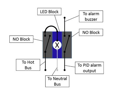
Do you have a back view diagram for the HLT alarm switch, so that I can double check my work?
Also curious as to how the HLT switch and buzzer function. I assume when you go to boil the HLT switch is turned on,(right click) and then once to temp the alarm sounds and the switch can be turned off. Assuming the switch only lights up when the switch is turned on.
Thank you.
Also curious as to how the HLT switch and buzzer function. I assume when you go to boil the HLT switch is turned on,(right click) and then once to temp the alarm sounds and the switch can be turned off. Assuming the switch only lights up when the switch is turned on.
Thank you.
Last edited:
OP
OP
MikeSkril
Well-Known Member
- Joined
- Feb 5, 2015
- Messages
- 401
- Reaction score
- 82
So it's working now?Inside cabinet- wort and water led buttons
OP
OP
MikeSkril
Well-Known Member
- Joined
- Feb 5, 2015
- Messages
- 401
- Reaction score
- 82
Do you have a diagram for the HLT alarm switch, so I can check my work?
Also curious as to how the HLT switch and buzzer function. I assume when you go to boil the HLT switch is turned on,(right click) and then once to temp the alarm sounds and the switch can be turned off. Assuming the switch only lights up when the switch is turned on.
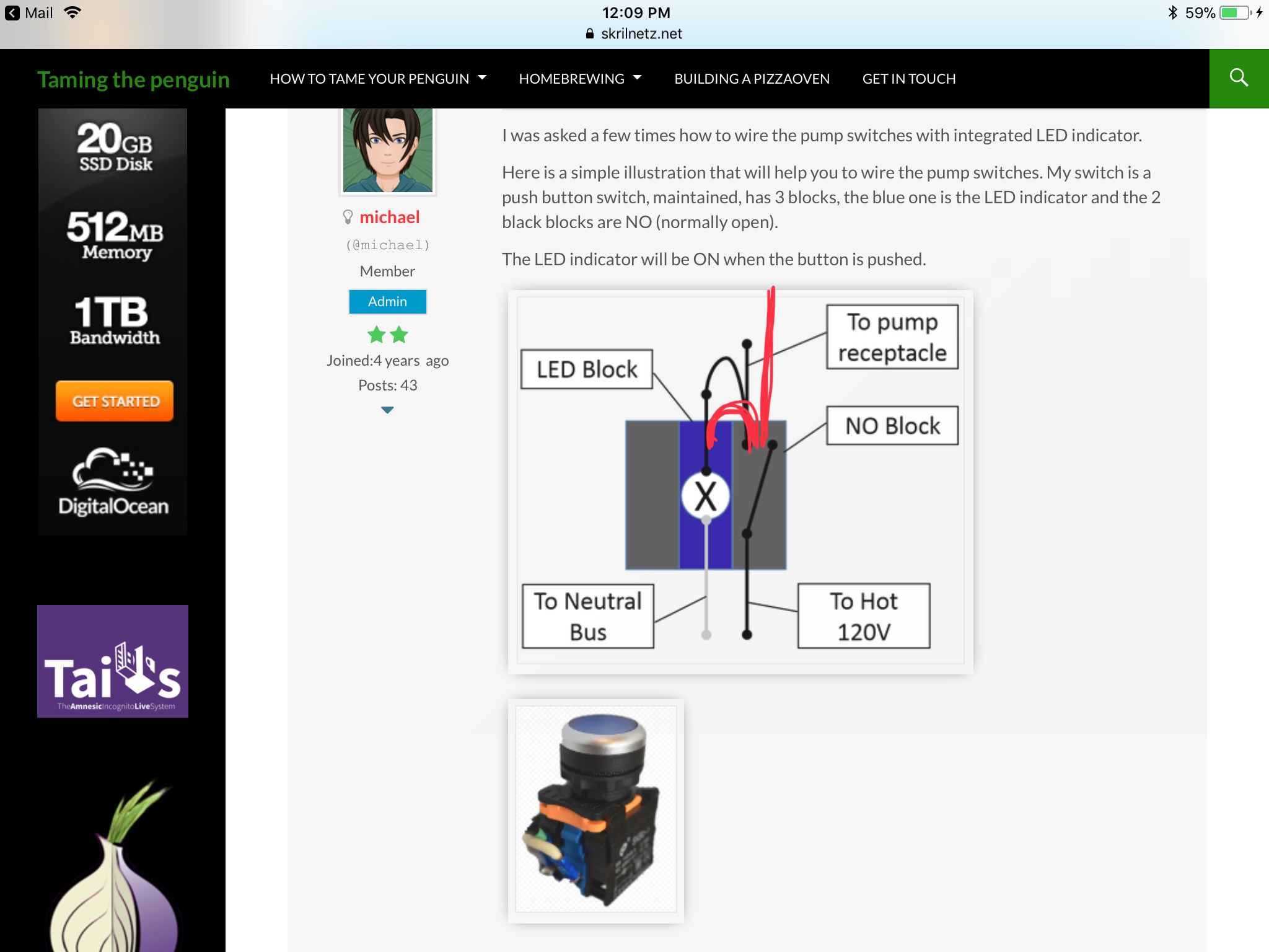
The LED will be on when the switch is in ON position. The alarm buzzer will only be activated if the alarm switch is in ON position and the HLT PID is triggering an alarm.
Turfgrass
Well-Known Member
Thank you for the diagram.
I found the initial cause for the breaker trip and I’ll be able to test everything again once I buy a fuse. I should be able to get to a store in the next day or so.
I found the initial cause for the breaker trip and I’ll be able to test everything again once I buy a fuse. I should be able to get to a store in the next day or so.


$7.79 ($7.79 / Count)
Craft A Brew - LalBrew Voss™ - Kveik Ale Yeast - For Craft Lagers - Ingredients for Home Brewing - Beer Making Supplies - (1 Pack)
Craft a Brew


$53.24
1pc Hose Barb/MFL 1.5" Tri Clamp to Ball Lock Post Liquid Gas Homebrew Kegging Fermentation Parts Brewer Hardware SUS304(Gas MFL)
Guangshui Weilu You Trading Co., Ltd


$49.95 ($0.08 / Fl Oz)
$52.99 ($0.08 / Fl Oz)
Brewer's Best - 1073 - Home Brew Beer Ingredient Kit (5 gallon), (Blueberry Honey Ale) Golden
Amazon.com


$76.92 ($2,179.04 / Ounce)
Brewing accessories 1.5" Tri Clamp to Ball Lock Post Liquid Gas Homebrew Kegging Fermentation Parts Brewer Hardware SUS304 Brewing accessories(Gas Hose Barb)
chuhanhandianzishangwu


![Craft A Brew - Safale S-04 Dry Yeast - Fermentis - English Ale Dry Yeast - For English and American Ales and Hard Apple Ciders - Ingredients for Home Brewing - Beer Making Supplies - [1 Pack]](https://m.media-amazon.com/images/I/41fVGNh6JfL._SL500_.jpg)
$6.95 ($17.38 / Ounce)
$7.47 ($18.68 / Ounce)
Craft A Brew - Safale S-04 Dry Yeast - Fermentis - English Ale Dry Yeast - For English and American Ales and Hard Apple Ciders - Ingredients for Home Brewing - Beer Making Supplies - [1 Pack]
Hobby Homebrew

$33.99 ($17.00 / Count)
$41.99 ($21.00 / Count)
2 Pack 1 Gallon Large Fermentation Jars with 3 Airlocks and 2 SCREW Lids(100% Airtight Heavy Duty Lid w Silicone) - Wide Mouth Glass Jars w Scale Mark - Pickle Jars for Sauerkraut, Sourdough Starter
Qianfenie Direct


$22.00 ($623.23 / Ounce)
AMZLMPKNTW Ball Lock Sample Faucet 30cm Reinforced Silicone Hose Secondary Fermentation Homebrew Kegging joyful
无为中南商贸有限公司


$719.00
$799.00
EdgeStar KC2000TWIN Full Size Dual Tap Kegerator & Draft Beer Dispenser - Black
Amazon.com


$176.97
1pc Commercial Keg Manifold 2" Tri Clamp,Ball Lock Tapping Head,Pressure Gauge/Adjustable PRV for Kegging,Fermentation Control
hanhanbaihuoxiaoshoudian


$58.16
HUIZHUGS Brewing Equipment Keg Ball Lock Faucet 30cm Reinforced Silicone Hose Secondary Fermentation Homebrew Kegging Brewing Equipment
xiangshuizhenzhanglingfengshop


$53.24
1pc Hose Barb/MFL 1.5" Tri Clamp to Ball Lock Post Liquid Gas Homebrew Kegging Fermentation Parts Brewer Hardware SUS304(Liquid Hose Barb)
yunchengshiyanhuqucuichendianzishangwuyouxiangongsi

$44.99
$49.95
Craft A Brew - Mead Making Kit – Reusable Make Your Own Mead Kit – Yields 1 Gallon of Mead
Craft a Brew


$20.94
$29.99
The Brew Your Own Big Book of Clone Recipes: Featuring 300 Homebrew Recipes from Your Favorite Breweries
Amazon.com


$479.00
$559.00
EdgeStar KC1000SS Craft Brew Kegerator for 1/6 Barrel and Cornelius Kegs
Amazon.com
Don't keep us in suspense... what was causing the trip? And, congrats on figuring it out.Thank you for the diagram.
I found the initial cause for the breaker trip and I’ll be able to test everything again once I buy a fuse. I should be able to get to a store in the next day or so.
Brew on

Turfgrass
Well-Known Member
It was a wiring mistake at the power on/off switch.Don't keep us in suspense... what was causing the trip? And, congrats on figuring it out.
Brew on
Turfgrass
Well-Known Member
I don’t think it was the key switch after all and the breaker in the sub panel continues to trip.
I disconnected most of the wiring to try and isolate the problem and it’s not the ssr’s or the receptacles for the heating elements. All I have connected now is the power linking the HLT and Boil contractor, the fuse link and the runs connected to the 120volt coils of all three contractors and it still trips. The breaker was tripping with the fuse removed from its harness. Starting to wonder if there is a problem with the key switch or the main contractor/contractors???
I disconnected most of the wiring to try and isolate the problem and it’s not the ssr’s or the receptacles for the heating elements. All I have connected now is the power linking the HLT and Boil contractor, the fuse link and the runs connected to the 120volt coils of all three contractors and it still trips. The breaker was tripping with the fuse removed from its harness. Starting to wonder if there is a problem with the key switch or the main contractor/contractors???
Can you post some overview and close up (multiple angle) pics of the key switch and contactor(s). Need to be able to tell where all wires are connected, and have some idea where the wires go.I don’t think it was the key switch after all and the breaker in the sub panel continues to trip.
I disconnected most of the wiring to try and isolate the problem and it’s not the ssr’s or the receptacles for the heating elements. All I have connected now is the power linking the HLT and Boil contractor, the fuse link and the runs connected to the 120volt coils of all three contractors and it still trips. The breaker was tripping with the fuse removed from its harness. Starting to wonder if there is a problem with the key switch or the main contractor/contractors???
Brew on
Turfgrass
Well-Known Member

Turfgrass
Well-Known Member
There are some difference between the pictures and sketches on the 30amp panel build page. For example, the fuse run off the boil contractor and the boil and HLT contractors both have grounds on one of the coil sides.
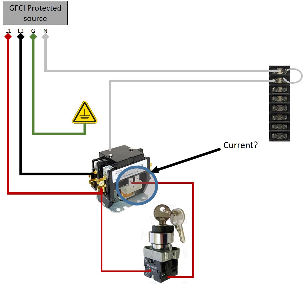
A ground connection to any contactor coil will cause the GFCI to trip, as the coil current will return thru ground rather than returning thru the neutral.
Brew on
Brew on
Turfgrass
Well-Known Member
I didn’t ground the contractors.
OP
OP
MikeSkril
Well-Known Member
- Joined
- Feb 5, 2015
- Messages
- 401
- Reaction score
- 82
The best I could was a drawing of what’s connected now. A picture wouldn't help, because of the disconnected wires and mess created. Power from the sub panel enters from the bottom of the main contractor.
I don't see any mistake on the sketch. I know it's a pain in the ass, but I would test 1 component at a time.
At first, I would just connect the main contactor, with the main switch. Does that work? Does the main contactor switch?
Now connect the next contactor and test again…and so on.
You will find the bad connection, but you must work systematic to find it.
Turfgrass
Well-Known Member
Yes, I was working my way in that direction, but looks like I have to bring it right down to the key and main contractor only.
I understand contactors to deliver power when the contractor taps connect, but I’m a bit lost with how the 120v coil functions.
Does the key in the on position allow for the taps to make a connection and thus allows for electricity to move to the opposite side of the contractor?
I understand contactors to deliver power when the contractor taps connect, but I’m a bit lost with how the 120v coil functions.
Does the key in the on position allow for the taps to make a connection and thus allows for electricity to move to the opposite side of the contractor?
OP
OP
MikeSkril
Well-Known Member
- Joined
- Feb 5, 2015
- Messages
- 401
- Reaction score
- 82
I understand contactors to deliver power when the contractor taps connect, but I’m a bit lost with how the 120v coil functions.
Does the key in the on position allow for the taps to make a connection and thus allows for electricity to move to the opposite side of the contractor?
The coil functions like a switch. When current is applied, it closes, letting current flow to the other side.

Turfgrass
Well-Known Member
Gotcha.
So, the wire position on the 3 and 4 spot of the key switch doesn’t really matter, bc there is a connection either way once power is supplied?? I assume the connection tabs on both sides of the contractors are 120v only.
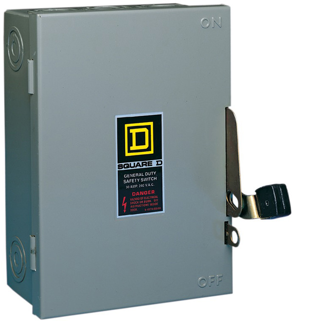
Separate topic- I originally wired my panel to be portable should I decide to brew indoors or out and currently it’s wired with a prong and outlet receptacle. I’ve decide to make my setup 100% indoors, so is there a 240v stop switch/level that I could install in place of the prong and outlet setup? Otherwise, hardwiring would mean I have to use the breaker in my sub or main panel to kill power and there’s a distance between the brew setup and those shut offs. I now see a value to the spa type box with a kill lever. Just something to interrupt power.
So, the wire position on the 3 and 4 spot of the key switch doesn’t really matter, bc there is a connection either way once power is supplied?? I assume the connection tabs on both sides of the contractors are 120v only.
Separate topic- I originally wired my panel to be portable should I decide to brew indoors or out and currently it’s wired with a prong and outlet receptacle. I’ve decide to make my setup 100% indoors, so is there a 240v stop switch/level that I could install in place of the prong and outlet setup? Otherwise, hardwiring would mean I have to use the breaker in my sub or main panel to kill power and there’s a distance between the brew setup and those shut offs. I now see a value to the spa type box with a kill lever. Just something to interrupt power.
OP
OP
MikeSkril
Well-Known Member
- Joined
- Feb 5, 2015
- Messages
- 401
- Reaction score
- 82
Gotcha.
So, the wire position on the 3 and 4 spot of the key switch doesn’t really matter, bc there is a connection either way once power is supplied??
Your key switch needs at least one NO (normally open) block. When you turn the key the block will close and let current flow.
Gotcha.
I assume the connection tabs on both sides of the contractors are 120v only.
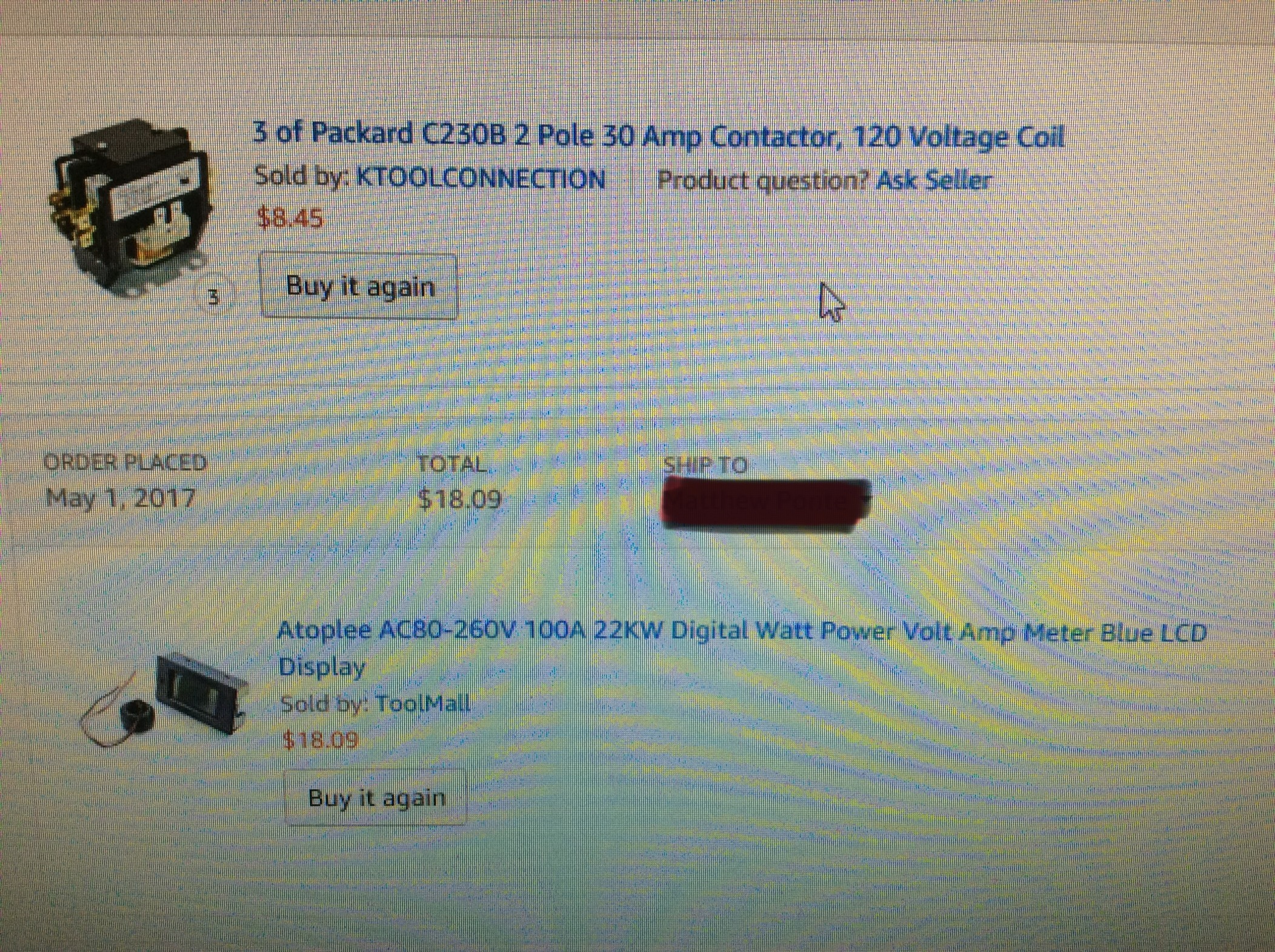
The coil of your contactor must be 120V. Which model do you have?
Separate topic- I originally wired my panel to be portable should I decide to brew indoors or out and currently it’s wired with a prong and outlet receptacle. I’ve decide to make my setup 100% indoors, so is there a 240v stop switch/level that I could install in place of the prong and outlet setup? Otherwise, hardwiring would mean I have to use the breaker in my sub or main panel to kill power and there’s a distance between the brew setup and those shut offs. I now see a value to the spa type box with a kill lever. Just something to interrupt power.
Where is your GFCI? In the main panel?
The key switch would be enough to cut power but if you are not feeling good about that, just unplug the plug. You could also add a 240V disconnect to cut power.
I didn’t ground the contractors.
So, then what is the proper interpretation of the red highlighted text below (from your previous post)? I read it as you connected one of the contactor coil connections to ground.
There are some difference between the pictures and sketches on the 30amp panel build page. For example, the fuse run off the boil contractor and the boil and HLT contractors both have grounds on one of the coil sides.
Brew on
Turfgrass
Well-Known Member
Your key switch needs at least one NO (normally open) block. When you turn the key the block will close and let current flow.
The coil of your contactor must be 120V. Which model do you have?
Where is your GFCI? In the main panel?
The key switch would be enough to cut power but if you are not feeling good about that, just unplug the plug. You could also add a 240V disconnect to cut power.
The 30amp gfi breaker is in the sub panel. I like the idea of the 240v disconnect.
Here is my contact purchase thru amazon.
Attachments
OP
OP
MikeSkril
Well-Known Member
- Joined
- Feb 5, 2015
- Messages
- 401
- Reaction score
- 82
The 30amp gfi breaker is in the sub panel. I like the idea of the 240v disconnect.
Here is my contact purchase thru amazon.
Ok. 120V coil, so your are fine.
Turfgrass
Well-Known Member
So, I removed everything but the key switch wires and power is fine coming into the main contractor and the breaker no longer trips when the key is turned on.
Electricity is detected on the opposite side of the contractor, however, once I connect the black wire to link up the other two contractors, power is lost only on that side of the contractor. No breakers trip. The wire alone without connection to the other contractors will lose power.
Electricity is detected on the opposite side of the contractor, however, once I connect the black wire to link up the other two contractors, power is lost only on that side of the contractor. No breakers trip. The wire alone without connection to the other contractors will lose power.
OP
OP
MikeSkril
Well-Known Member
- Joined
- Feb 5, 2015
- Messages
- 401
- Reaction score
- 82
however, once I connect the black wire to link up the other two contractors, power is lost only on that side of the contractor. No breakers trip. The wire alone without connection to the other contractors will lose power.
I don't understand this part...
Turfgrass
Well-Known Member

Okay. I have power going into the main contractor and the breaker doesn’t trip when the key is on and there is voltage on the opposite site of the contractor. Once I connect the 10AWG black wire to the HLT contractor or just connecting the black wire alone and not to the HLT post, electricity is lost on that side of the main contractor. I’m not detecting electricity upstream of the main contractor. No other connection in that picture have been made at this point.
OP
OP
MikeSkril
Well-Known Member
- Joined
- Feb 5, 2015
- Messages
- 401
- Reaction score
- 82
View attachment 554268
Okay. I have power going into the main contractor and the breaker doesn’t trip when the key is on and there is voltage on the opposite site of the contractor. Once I connect the 10AWG black wire to the HLT contractor or just connecting the black wire alone and not to the HLT post, electricity is lost on that side of the main contractor. I’m not detecting electricity upstream of the main contractor. No other connection in that picture have been made at this point.
How do you measure? You have a multimeter?
So you hear the main contactor switching when you turn the key, right?
You have current flowing to the other side on both poles, right?
Now the 2 poles have current on it until the main contactor switches off again (turning the key to OFF). And you would hear when it switches. So, if your breaker isn't tripping and the contactor is closed, there will be current on red and black.
Nice System and video showing it
Turfgrass
Well-Known Member
I was just testing the upstream flow with a sensor that lights up.
I used a multimeter and no voltage going through when the key is turned on. I didn’t hear the contacts being made either. Def have 240 and 120 going thru the key switch. Bad contractor?
I used a multimeter and no voltage going through when the key is turned on. I didn’t hear the contacts being made either. Def have 240 and 120 going thru the key switch. Bad contractor?
OP
OP
MikeSkril
Well-Known Member
- Joined
- Feb 5, 2015
- Messages
- 401
- Reaction score
- 82
I was just testing the upstream flow with a sensor that lights up.
I used a multimeter and no voltage going through when the key is turned on. I didn’t hear the contacts being made either. Def have 240 and 120 going thru the key switch. Bad contractor?
When the key is on, is there current on the coil?
Turfgrass
Well-Known Member
I believe so, but I’d have to double check. I don’t have the neutral side of the 120v coil connected at the moment.
Without the neutral side of the coil connected, the contactor will not turn on. Current flows in a loop, and the neutral is part of that loop for a 120V circuit. Break the loop anywhere, and current stops flowing.I believe so, but I’d have to double check. I don’t have the neutral side of the 120v coil connected at the moment.
Brew on
Turfgrass
Well-Known Member
Understood. I’ll connect the neutral and test again with the multimeter. Won’t be able to report back until Tuesday. Skiing ⛷
seandalton
New Member
- Joined
- Aug 18, 2014
- Messages
- 3
- Reaction score
- 0
What type of wires did you use internally? I have some extra SOOW 10 gauge wire I could use, but heard that it should be THHM?
Turfgrass
Well-Known Member
Back a little bit early from skiing and back to working on the brew panel.
Today I double checked everything with a multimeter and I can confirm that 240v is going into the contractor, (does it matter which side it enters??). Then I checked the key switch with power on and off and I do have 120v at the coil. However, once I connect the neutral wire to the coil on opposite side of the contractor, the breaker is tripped. Nothing else is connected to the neutral bus other than the white wire from the sub panel.
Faulty contractor??
Sounds more like the neutral on the GFCI is not hooked up correctly, so that when some current flows thru the neutral, the GFCI thinks it is leakage rather than legit return current.Back a little bit early from skiing and back to working on the brew panel.
Today I double checked everything with a multimeter and I can confirm that 240v is going into the contractor, (does it matter which side it enters??). Then I checked the key switch with power on and off and I do have 120v at the coil. However, once I connect the neutral wire to the coil on opposite side of the contractor, the breaker is tripped. Nothing else is connected to the neutral bus other than the white wire from the sub panel.
Faulty contractor??
Brew on
Turfgrass
Well-Known Member

Turfgrass
Well-Known Member
What a dope. I have the 10-3 neutral wire connected to the neutral bus instead of the third spot on the gfi breaker. Does it matter the location or can it be placed right next to the black? Was thinking it should be place where the red wire is??
Yeah that 10-3 neutral needs to wire into the GFCI...that’s why it is tripping...in is not equaling the out...here’s the image from the breaker I’m about to install...it should be labeled right on your breaker itself too, probably next to the black

Turfgrass
Well-Known Member
The breaker was labeled load on both sides of the breaker, so I left everything alone and put the white from the 10-3 in the position above the white, curly gfi wire. I pulled the breaker out and wired it correctly.
Powering up and checking the brew panel.
Powering up and checking the brew panel.
Similar threads
- Replies
- 20
- Views
- 773
- Replies
- 4
- Views
- 1K
- Replies
- 10
- Views
- 3K
