You are using an out of date browser. It may not display this or other websites correctly.
You should upgrade or use an alternative browser.
You should upgrade or use an alternative browser.
How To: BrewPi Over Bluetooth
- Thread starter day_trippr
- Start date

Help Support Homebrew Talk:
This site may earn a commission from merchant affiliate
links, including eBay, Amazon, and others.
ksga
Member
- Joined
- Apr 18, 2016
- Messages
- 10
- Reaction score
- 0
Thanks for the great guide - made me a happy chappy for a long time 
I thought I would be even more happy replacing my faithful old RPi model B with a Zero W when it came out... However, so far it's only made me a lot more frustrated
On the old Model B I used Raspbian Wheezy, but since I have had trouble making it run on the ZW, I decided to switch to Jessie.
My setup is completely headless, so I have to make do with the command line.
Originally I used your instructions in the first post and coupled it with this:
https://www.homebrewtalk.com/showpost.php?p=6624689&postcount=29
After some googling around I discovered that bluez-simple-agent (bluetooth-agent) was discarded, and that I should use bluetoothctl instead.
Long story short - I can't make a rfcomm connection to more than one minion (and I'd really like to get at least two running).
So far my best solution is:
1. Pair/trust both minions using bluetoothctl
2. Create and enable two services: /etc/systemd/system/rfcomm(1+2).service containing:
On reboot /dev/rfcomm0 is created, but checking the status of the services reveal the problem:
rfcomm1 (working):
rfcomm2 (dead ):
On my old setup I used /etc/bluetooth/rfcomm.conf to define the rfcomm connections, but it seems it doesn't make a difference anymore.
Any and all suggestions are welcome... (brew day tomorrow so would like to have it running before fermentation...)
I thought I would be even more happy replacing my faithful old RPi model B with a Zero W when it came out... However, so far it's only made me a lot more frustrated
On the old Model B I used Raspbian Wheezy, but since I have had trouble making it run on the ZW, I decided to switch to Jessie.
My setup is completely headless, so I have to make do with the command line.
Originally I used your instructions in the first post and coupled it with this:
https://www.homebrewtalk.com/showpost.php?p=6624689&postcount=29
After some googling around I discovered that bluez-simple-agent (bluetooth-agent) was discarded, and that I should use bluetoothctl instead.
Long story short - I can't make a rfcomm connection to more than one minion (and I'd really like to get at least two running).
So far my best solution is:
1. Pair/trust both minions using bluetoothctl
2. Create and enable two services: /etc/systemd/system/rfcomm(1+2).service containing:
Code:
[Unit]
Description=RFCOMM service
After=bluetooth.service
Requires=bluetooth.service

[Service]
ExecStart=/usr/bin/rfcomm connect hci0 xx:xx:xx:xx:xx:xx 1

[Install]
WantedBy=multi-user.target
On reboot /dev/rfcomm0 is created, but checking the status of the services reveal the problem:
rfcomm1 (working):
Code:
pi@brewpi:~ $ sudo systemctl status rfcomm1
● rfcomm1.service - RFCOMM service
   Loaded: loaded (/etc/systemd/system/rfcomm1.service; enabled)
   Active: active (running) since Thu 2017-03-30 15:30:49 CEST; 37min ago
 Main PID: 606 (rfcomm)
   CGroup: /system.slice/rfcomm1.service
           └─606 /usr/bin/rfcomm connect hci0 20:16:07:25:12:63 1

Mar 30 15:30:49 brewpi systemd[1]: Started RFCOMM service.
Code:
pi@brewpi:~ $ sudo systemctl status rfcomm2 -l
● rfcomm2.service - RFCOMM service
   Loaded: loaded (/etc/systemd/system/rfcomm2.service; enabled)
   Active: inactive (dead) since Thu 2017-03-30 15:30:53 CEST; 37min ago
  Process: 604 ExecStart=/usr/bin/rfcomm connect hci0 20:16:07:25:09:80 1 (code=exited, status=0/SUCCESS)
 Main PID: 604 (code=exited, status=0/SUCCESS)

Mar 30 15:30:49 brewpi systemd[1]: Started RFCOMM service.
Mar 30 15:30:53 brewpi rfcomm[604]: Can't create RFCOMM TTY: Address already in use
On my old setup I used /etc/bluetooth/rfcomm.conf to define the rfcomm connections, but it seems it doesn't make a difference anymore.
Any and all suggestions are welcome... (brew day tomorrow so would like to have it running before fermentation...)
ksga
Member
- Joined
- Apr 18, 2016
- Messages
- 10
- Reaction score
- 0
If you had it all running without a problem on the pi b then why don't you just use the same sd card and put it in the zw. then all you should need to do is update the firmware
Might have to go down that road.... (would of course be considered a defeat by the red guy inside my head)
Last night I decided to start over on a fresh Rapibian Lite image (Jessie).
Installed Brewpi in a multiple chamber setup following this guide (not doing the udev stuff since I won't be using USB anyhow):
http://diybrewpi.wikia.com/wiki/Multiple_Fermentation_Chamber_Control_with_BrewPi
Looking at day_trippr's post (page 36 I think) I added LXDE following this guide:
https://www.raspberrypi.org/forums/viewtopic.php?f=66&t=133691
This time - using Blueman-manager (started from the LXDE menu entry) I was actually able to pair and connect to the minions without any difficulty
Following day_trippr's instructions I added the
Code:
sudo rfcomm bind xx:xx:xx:xx:xx:xx 1On reboot however, only rfcomm0 is created, and my second minion is still out of reach...
I'm starting to wonder if this could somehow be a limitation on the RPi onboard BT-module?
Read somewhere about someone not being able to stream music to multiple speakers when using the onboard BT, but doing it without hazzle using a dongle...
EDIT:
I decided to give it a shot, updating firmware on my old setup and transferring it to the Zero W.
It boots okay, but the builtin WiFi won't accept the configuration - plugged in a WiFi dongle and it connected to my network.
Both rfcomm devices are created as on the old setup:
Code:
pi@raspberrypi ~ $ ls /dev/rf*
/dev/rfcomm0  /dev/rfcomm1  /dev/rfkill
The maintenance panel log shows:
Mar 31 2017 11:26:10 Opening serial port
Mar 31 2017 11:26:20 Errors while opening serial port:
Code:
[Errno 113] could not open port /dev/rfcomm0: [Errno 113] No route to host: '/dev/rfcomm0'
Could not configure port: (25, 'Inappropriate ioctl for device')
dmesg shows bluetootg initializing as I would expect it to:
Code:
pi@raspberrypi ~ $ dmesg | grep Blue
[   38.956871] Bluetooth: Core ver 2.21
[   38.957085] Bluetooth: HCI device and connection manager initialized
[   38.959091] Bluetooth: HCI socket layer initialized
[   38.959131] Bluetooth: L2CAP socket layer initialized
[   38.959227] Bluetooth: SCO socket layer initialized
[   38.998342] Bluetooth: RFCOMM TTY layer initialized
[   38.998392] Bluetooth: RFCOMM socket layer initialized
[   38.998429] Bluetooth: RFCOMM ver 1.11
[   39.016018] Bluetooth: BNEP (Ethernet Emulation) ver 1.3
[   39.016044] Bluetooth: BNEP filters: protocol multicast
[   39.016086] Bluetooth: BNEP socket layer initialized
Bluetooth appear to be running:
Code:
pi@raspberrypi ~ $ /etc/init.d/bluetooth status
[ ok ] bluetooth is running.
But it appears that the BT device was not loaded:
Code:
pi@raspberrypi ~ $ hciconfig -a
pi@raspberrypi ~ $
EDIT 2 - Follow up on reusing old Wheezy image...
Finally discarded the idea. Tried adding jessie repo to install pi-bluetooth which seems to be essential. No luck installing it, and the whole system became very unstable, loosing connection or crashing every few minutes...
So back to making it run on LXDE on top of Jessie Raspbian Lite
ksga
Member
- Joined
- Apr 18, 2016
- Messages
- 10
- Reaction score
- 0
Decided to compare the output from hciconfig:
CSR4 on Model B (wheezy)
Onboard module on Zero W (jessie)
Any ideas? Could the UART bus be causing problems? or is it perhaps the missing Link Policies "PARK" and "HOLD" that is somehow missing?
CSR4 on Model B (wheezy)
Code:
pi@raspberrypi ~ $ hciconfig -a
hci0:   Type: BR/EDR  Bus: USB
        BD Address: 00:1A:7D:DA:71:0B  ACL MTU: 310:10  SCO MTU: 64:8
        UP RUNNING
        RX bytes:15380 acl:309 sco:0 events:388 errors:0
        TX bytes:3111 acl:98 sco:0 commands:151 errors:0
        Features: 0xff 0xff 0x8f 0xfe 0xdb 0xff 0x5b 0x87
        Packet type: DM1 DM3 DM5 DH1 DH3 DH5 HV1 HV2 HV3
        Link policy: RSWITCH HOLD SNIFF PARK
        Link mode: SLAVE ACCEPT
        Name: 'raspberrypi-0'
        Class: 0x420100
        Service Classes: Networking, Telephony
        Device Class: Computer, Uncategorized
        HCI Version: 4.0 (0x6)  Revision: 0x22bb
        LMP Version: 4.0 (0x6)  Subversion: 0x22bb
        Manufacturer: Cambridge Silicon Radio (10)
Code:
pi@brewpi:~ $ hciconfig -a
hci0:   Type: BR/EDR  Bus: UART
        BD Address: B8:27:EB:9E:57:D7  ACL MTU: 1021:8  SCO MTU: 64:1
        UP RUNNING PSCAN
        RX bytes:30262 acl:657 sco:0 events:574 errors:0
        TX bytes:5467 acl:184 sco:0 commands:171 errors:0
        Features: 0xbf 0xfe 0xcf 0xfe 0xdb 0xff 0x7b 0x87
        Packet type: DM1 DM3 DM5 DH1 DH3 DH5 HV1 HV2 HV3
        Link policy: RSWITCH SNIFF
        Link mode: SLAVE ACCEPT
        Name: 'brewpi'
        Class: 0x0c0000
        Service Classes: Rendering, Capturing
        Device Class: Miscellaneous,
        HCI Version: 4.1 (0x7)  Revision: 0xb6
        LMP Version: 4.1 (0x7)  Subversion: 0x2209
Manufacturer: Broadcom Corporation (15)wbarber69
Well-Known Member
- Joined
- Oct 13, 2013
- Messages
- 2,191
- Reaction score
- 263
Dunno haven't used my pizw yet. just figured that since I had no problem just sticking my pi b sd card into the z 1.0 gave me no issues, figured that since it's the same pi only now with wifi and bt it wouldn't be that hard
. Figures


$176.97
1pc Commercial Keg Manifold 2" Tri Clamp,Ball Lock Tapping Head,Pressure Gauge/Adjustable PRV for Kegging,Fermentation Control
hanhanbaihuoxiaoshoudian


$58.16
HUIZHUGS Brewing Equipment Keg Ball Lock Faucet 30cm Reinforced Silicone Hose Secondary Fermentation Homebrew Kegging Brewing Equipment
xiangshuizhenzhanglingfengshop


$44.99
$49.95
Craft A Brew - Mead Making Kit – Reusable Make Your Own Mead Kit – Yields 1 Gallon of Mead
Craft a Brew

$53.24
1pc Hose Barb/MFL 1.5" Tri Clamp to Ball Lock Post Liquid Gas Homebrew Kegging Fermentation Parts Brewer Hardware SUS304(Liquid Hose Barb)
yunchengshiyanhuqucuichendianzishangwuyouxiangongsi


$22.00 ($623.23 / Ounce)
AMZLMPKNTW Ball Lock Sample Faucet 30cm Reinforced Silicone Hose Secondary Fermentation Homebrew Kegging joyful
无为中南商贸有限公司
![Craft A Brew - Safale BE-256 Yeast - Fermentis - Belgian Ale Dry Yeast - For Belgian & Strong Ales - Ingredients for Home Brewing - Beer Making Supplies - [3 Pack]](https://m.media-amazon.com/images/I/51bcKEwQmWL._SL500_.jpg)


$33.99 ($17.00 / Count)
$41.99 ($21.00 / Count)
2 Pack 1 Gallon Large Fermentation Jars with 3 Airlocks and 2 SCREW Lids(100% Airtight Heavy Duty Lid w Silicone) - Wide Mouth Glass Jars w Scale Mark - Pickle Jars for Sauerkraut, Sourdough Starter
Qianfenie Direct


$53.24
1pc Hose Barb/MFL 1.5" Tri Clamp to Ball Lock Post Liquid Gas Homebrew Kegging Fermentation Parts Brewer Hardware SUS304(Gas MFL)
Guangshui Weilu You Trading Co., Ltd


$159.99 ($26.66 / Count)
3M High Flow Series System BREW120-MS, 5616001, For Brewed Coffee and Hot Tea, Valve-in-Head Design
SpaceCityProviders


$10.99 ($31.16 / Ounce)
Hornindal Kveik Yeast for Homebrewing - Mead, Cider, Wine, Beer - 10g Packet - Saccharomyces Cerevisiae - Sold by Shadowhive.com
Shadowhive


$719.00
$799.00
EdgeStar KC2000TWIN Full Size Dual Tap Kegerator & Draft Beer Dispenser - Black
Amazon.com

$479.00
$559.00
EdgeStar KC1000SS Craft Brew Kegerator for 1/6 Barrel and Cornelius Kegs
Amazon.com


$20.94
$29.99
The Brew Your Own Big Book of Clone Recipes: Featuring 300 Homebrew Recipes from Your Favorite Breweries
Amazon.com


$7.79 ($7.79 / Count)
Craft A Brew - LalBrew Voss™ - Kveik Ale Yeast - For Craft Lagers - Ingredients for Home Brewing - Beer Making Supplies - (1 Pack)
Craft a Brew


$76.92 ($2,179.04 / Ounce)
Brewing accessories 1.5" Tri Clamp to Ball Lock Post Liquid Gas Homebrew Kegging Fermentation Parts Brewer Hardware SUS304 Brewing accessories(Gas Hose Barb)
chuhanhandianzishangwu


$28.98
Five Star - 6022b_ - Star San - 32 Ounce - High Foaming Sanitizer
Great Fermentations of Indiana

srmid
New Member
This is just a short post to advise that my DIY RPi/Arduino Brewpi was reconfigured to a BrewPi over Bluetooth setup without any problems following @day_trippr's posts #343 and #352.
Special thanks to @day_trippr and everyone else who has contributed to this thread.
Special thanks to @day_trippr and everyone else who has contributed to this thread.
[ETA: In order to "Future-Proof" this article, I have created a page for it on the BrewPi Remix website. You can read the most up to date version there.]
I am NOT sure when this changed. @day_trippr is running Wheezy and Jessie and uses the "old" way of setting up a BT device. I'm using Stretch with bluetoothd 5.43 and the method by which you set up /dev/rfcomm* devices with the rfcomm.conf file in /etc/bluetooth is no longer supported. I'm sure someone somewhere could tell me WHY this is better. I'm sure we'd hear some crap about "cloud-enabled" like they tell me with all my favorite Ubuntu items that no longer work.
Anyway, here's how you can get the devices enabled with Stretch. To start with, make sure your HC-05/6 is powered up in its production configuration. At this point it's probably flashing 2-3 times per second. Then, prove to yourself that there's no rfcomm* devices:
Next, execute the new CLI for bluez, "bluetoothctl":
The controller listed is your local Pi's controller. After this we need to turn on and configure the "agent" which is the process that allows you to enter the pairing codes when required:
The next thing to do is allow the system to scan for local devices. If you have a "busy" area bluetooth-wise, you may get a lot of spam. Just let it run about 10 seconds and if you are living a clean life you will see your target BT device and it's MAC address. After that you can turn off the scan.
You may have to scroll up to find it, but if you gave it a friendly name ("Chamber 1" in my case), you should see the MAC followed by that name. Next, you will pair with your device with the pair command. It will prompt you to enter the code which is generally 1234 or 0000 unless you change it:
At this point your BT dongle is probably flashing once every two seconds. It's paired and trusted as you can see by issuing the 'info' command:
I noticed that if you power-cycle the BT dongle at this point, it will go back to flashing 2-3 times/second but that doesn't seem to affect things. You can exit or quit back to the shell prompt:
So, it's paired and trusted but still not visible in the device list:
Next, we need to bind it to the device:
It seems like the command runs till something touches the device (which is why we background it with the trailing '&'.) In that command the '0' is the rfcomm device we want to assign, the MAC address should be obvious, and the 1 is the channel. Unless you know why you want to change this, use '1'. Now prove there is a device in the list (and see the background process exit):
Power-cycling the BT device at this point proves the device will reconnect after a power failure after about 10 seconds. What does not happen however is re-establish the device after a Pi reboot or power failure. We need a way to issue the rfcomm command after reboot (and after the bluetoothd starts.) Create a file named 'rfcomm0.service' in the '/etc/systemd/system/' directory and add the following information:
This will allow systemd to execute the rfcomm command binding that MAC to rfcomm0 after the bluetooth.service starts. To enable this unit file, issue the commands:
You can start it with the 'sudo systemctl start rfcomm0' command, but there's no reason to since it's already bound. If you check the status of this daemon after system reboot it will not be running, because it ran once and exited - which is all we needed it to do:
That's how you set up your BT devices now in Stretch! You'll notice that using the graphical interface is also not needed. Using this method, no additional packages are required as a matter of fact, all the packages are part of the stock distribution.
If you have multiple devices, you'd change the above steps using 1, 2, 3, etc., instead of 0. You would also need a systemd unit file for each device.
I am NOT sure when this changed. @day_trippr is running Wheezy and Jessie and uses the "old" way of setting up a BT device. I'm using Stretch with bluetoothd 5.43 and the method by which you set up /dev/rfcomm* devices with the rfcomm.conf file in /etc/bluetooth is no longer supported. I'm sure someone somewhere could tell me WHY this is better. I'm sure we'd hear some crap about "cloud-enabled" like they tell me with all my favorite Ubuntu items that no longer work.
Anyway, here's how you can get the devices enabled with Stretch. To start with, make sure your HC-05/6 is powered up in its production configuration. At this point it's probably flashing 2-3 times per second. Then, prove to yourself that there's no rfcomm* devices:
Code:
pi@brewpi:~ $ ls -al /dev/rfc*
ls: cannot access '/dev/rfc*': No such file or directory
Code:
pi@brewpi:~ $ sudo bluetoothctl
[NEW] Controller XX:XX:XX:XX:XX:XX brewpi [default]
Code:
[bluetooth]# agent on
Agent registered
[bluetooth]# default-agent
Default agent request successful
Code:
[bluetooth]# scan on
Discovery started
[CHG] Controller XX:XX:XX:XX:XX:XX Discovering: yes
[NEW] Device XX:XX:XX:XX:XX:XX XX-XX-XX-XX-XX-XX
[NEW] Device XX:XX:XX:XX:XX:XX [TV] Living room
[NEW] Device XX:XX:XX:XX:XX:XX Chamber 1
[...]
[bluetooth]# scan off
[...]
Discovery stopped
[CHG] Controller XX:XX:XX:XX:XX:XX Discovering: no
Code:
[bluetooth]# pair XX:XX:XX:XX:XX:XX
Attempting to pair with XX:XX:XX:XX:XX:XX
[CHG] Device XX:XX:XX:XX:XX:XX Connected: yes
Request PIN code
[agent] Enter PIN code: 1234
[CHG] Device XX:XX:XX:XX:XX:XX UUIDs: 00001101-0000-1000-8000-00805f9b34fb
[CHG] Device XX:XX:XX:XX:XX:XX ServicesResolved: yes
[CHG] Device XX:XX:XX:XX:XX:XX Paired: yes
Pairing successful
[CHG] Device XX:XX:XX:XX:XX:XX ServicesResolved: no
[CHG] Device XX:XX:XX:XX:XX:XX Connected: no
[bluetooth]# trust XX:XX:XX:XX:XX:XX
[CHG] Device XX:XX:XX:XX:XX:XX Trusted: yes
Changing XX:XX:XX:XX:XX:XX trust succeeded
Code:
[bluetooth]# info XX:XX:XX:XX:XX:XX
Device XX:XX:XX:XX:XX:XX
        Name: Chamber 1
        Alias: Chamber 1
        Class: 0x001f00
        Paired: yes
        Trusted: yes
        Blocked: no
        Connected: no
        LegacyPairing: yes
        UUID: Serial Port               (00001101-0000-1000-8000-00805f9b34fb)
Code:
[bluetooth]# exit
Agent unregistered
[DEL] Controller XX:XX:XX:XX:XX:XX brewpi [default]
pi@brewpi:~ $
Code:
pi@brewpi:~ $ ls -al /dev/rfc*
ls: cannot access '/dev/rfc*': No such file or directory
Code:
pi@brewpi:~ $ sudo rfcomm bind 0 XX:XX:XX:XX:XX:XX 1 > /dev/null 2>&1 &
[1] 3345
Code:
pi@brewpi:~ $ ls -al /dev/rfc*
crw-rw---- 1 root dialout 216,  0 Mar 16 13:31 /dev/rfcomm0
[1]+  Done                    sudo rfcomm bind 0 XX:XX:XX:XX:XX:XX 1 > /dev/null 2>&1
pi@brewpi:~ $
Code:
[Unit]
After=bluetooth.service

[Service]
ExecStart=/usr/bin/rfcomm bind 0 XX:XX:XX:XX:XX:XX 1 > /dev/null 2>&1 &

[Install]
WantedBy=default.target
Code:
pi@brewpi:~ $ sudo chown root:root /etc/systemd/system/rfcomm0.service
pi@brewpi:~ $ sudo chmod 664 /etc/systemd/system/rfcomm0.service
pi@brewpi:~ $ sudo systemctl daemon-reload
pi@brewpi:~ $ sudo systemctl enable rfcomm0
Created symlink /etc/systemd/system/default.target.wants/rfcomm0.service → /etc/systemd/system/rfcomm0.service.
pi@brewpi:~ $
Code:
pi@brewpi:~ $ sudo systemctl status rfcomm0
● rfcomm0.service
   Loaded: loaded (/etc/systemd/system/rfcomm0.service; enabled; vendor preset:
   Active: inactive (dead) since Sat 2019-03-16 13:43:59 CDT; 40s ago
  Process: 290 ExecStart=/usr/bin/rfcomm bind 0 XX:XX:XX:XX:XX:XX 1 > /dev/null 2>&1 & (code=exited, status=0/SUCCESS)
 Main PID: 290 (code=exited, status=0/SUCCESS)

Mar 16 13:43:59 brewpi systemd[1]: Started rfcomm0.service.If you have multiple devices, you'd change the above steps using 1, 2, 3, etc., instead of 0. You would also need a systemd unit file for each device.
Last edited:
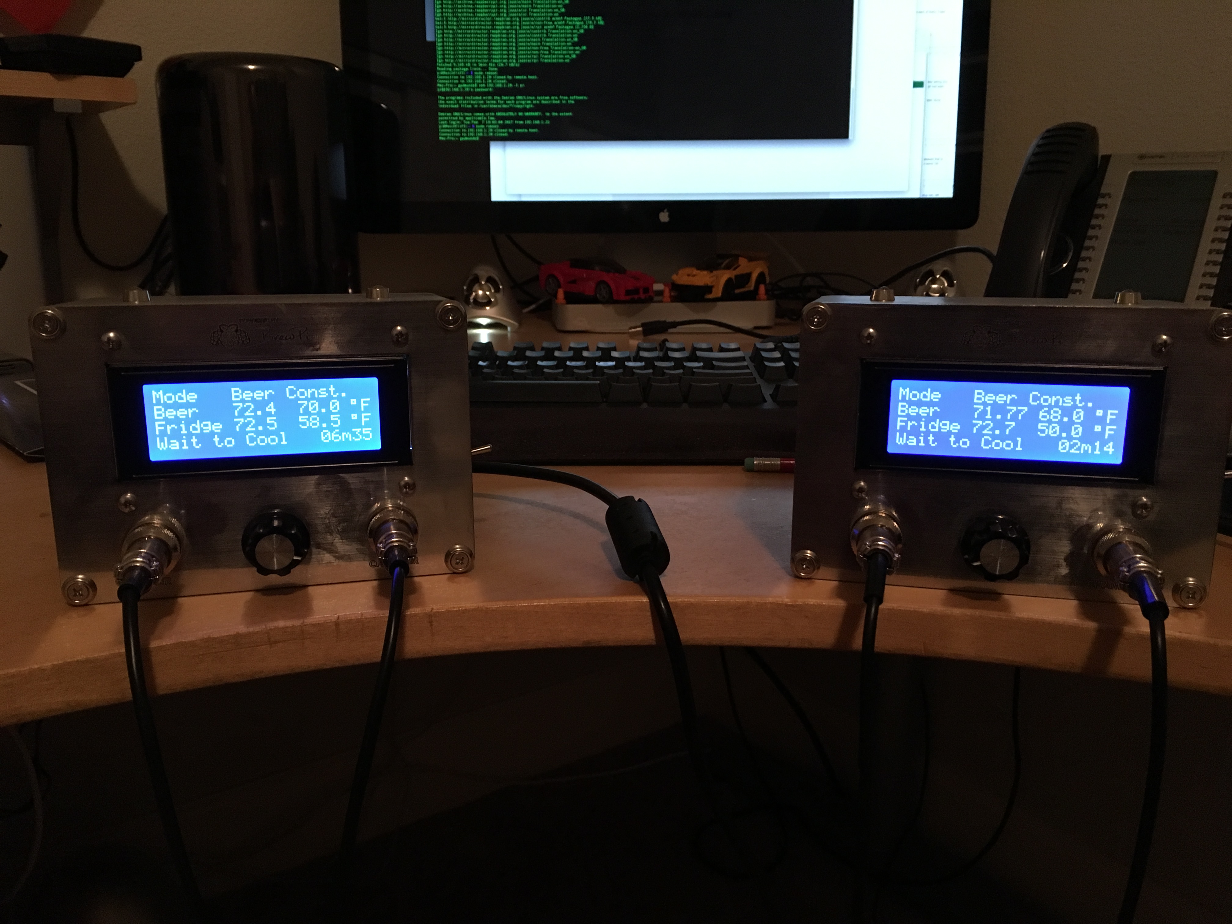
I thought you might also like to see what such a fancy setup looks like after the above work:

That's a gen-u-wine @CadiBrewer 1.1 shield right there ... waiting for an order for the 1.2 boards to clean things up.
The case is an extremely custom piece of work but I'd be happy to create one just like this for you for about $200.

That's a gen-u-wine @CadiBrewer 1.1 shield right there ... waiting for an order for the 1.2 boards to clean things up.
The case is an extremely custom piece of work but I'd be happy to create one just like this for you for about $200.
[ETA: In order to "Future-Proof" this article, I have created a page for it on the BrewPi Remix website. You can read the most up to date version there.]
I wanted to share what I think is an easier way to initially setup the HC-05 for BrewPi use. What @day_trippr lined out in the beginning is still valid, however for some people (like me, I'm not ashamed to admit it) "whipping up" a voltage splitter is not necessarily straightforward. It also leverages an Arduino and special sketch to set up the BT device which intimidates some folks. I found a different way that's likely more straightforward for most Windows users.
On Amazon I found a package with an HC-05 Bluetooth Module, a case for that module, Dupont jumpers, and a CP2102 USB to TTL Converter for $12.99 on Prime. That seems like a pretty good deal and provides some pretty good value for a person new to it. When you get a drawer full of "crap", the Dupont wires certainly have less value, but I kinda like the case. So, I'm writing this with that USB to TTL Converter being used:

DSD TECH HC-05 Bluetooth Module Kit with CP2102 USB to TTL Converter for Arduino
Buy that ... come back ... now we're ready.
Without further adieu, download some software. You'll probably need the CP2102 drivers, and to follow this you will definitely need the DSD TECH Bluetooth Tools Software. Download and install both of these (actually the "Bluetooth Tools" doesn't install, just unzip to a handy directory):
Don't plug the converter into the USB on your computer yet. Connect the TTL converter and the BT module like so:

I actually used the 3.3v the first time, the module will run on 3.3-6v for VIN I believe, but the data channel needs to be 3.3 volts. No worries, the USB to TTL converter handles that for you. Here's the connections in text form:
Converter <-> BT Module
3v3 <-> VIN
TXD <-> RXD
RXD <-> TXD
GND <-> GND
Basically, remember to connect transmit to receive and vice versa. When you are ready and the jumpers are connected properly, connect the device and set programming mode (called "AT mode") by doing the following:
Input low level to PIN34, supply power to the module, input high level to PIN34, then the module will enter to AT mode. Just kidding, I have no idea what that means either. I promised this would be for mortals.
Now run the "DSD TECH Bluetooth Tools Software" you unzipped. You will be executing "SHTester.exe".

So this is where you can go a couple different ways. In order to connect you do need to use a voltage splitter so that the voltage on the communications circuit does not burn out. If you are using @CadiBrewer's shield, this is handled for you. Connect as follows:
Shield <-> BT Module
TXD <-> RXD
RXD <-> TXD
GND <-> GND
VCC <-> VIN
If you are going all rogue and want to do it without a shield, at least you were able to skip the whole Arduino sketch setup thing. You will need:

The rest of the configuration is in this post above.
I wanted to share what I think is an easier way to initially setup the HC-05 for BrewPi use. What @day_trippr lined out in the beginning is still valid, however for some people (like me, I'm not ashamed to admit it) "whipping up" a voltage splitter is not necessarily straightforward. It also leverages an Arduino and special sketch to set up the BT device which intimidates some folks. I found a different way that's likely more straightforward for most Windows users.
On Amazon I found a package with an HC-05 Bluetooth Module, a case for that module, Dupont jumpers, and a CP2102 USB to TTL Converter for $12.99 on Prime. That seems like a pretty good deal and provides some pretty good value for a person new to it. When you get a drawer full of "crap", the Dupont wires certainly have less value, but I kinda like the case. So, I'm writing this with that USB to TTL Converter being used:
DSD TECH HC-05 Bluetooth Module Kit with CP2102 USB to TTL Converter for Arduino
Buy that ... come back ... now we're ready.
Without further adieu, download some software. You'll probably need the CP2102 drivers, and to follow this you will definitely need the DSD TECH Bluetooth Tools Software. Download and install both of these (actually the "Bluetooth Tools" doesn't install, just unzip to a handy directory):
Don't plug the converter into the USB on your computer yet. Connect the TTL converter and the BT module like so:
I actually used the 3.3v the first time, the module will run on 3.3-6v for VIN I believe, but the data channel needs to be 3.3 volts. No worries, the USB to TTL converter handles that for you. Here's the connections in text form:
Converter <-> BT Module
3v3 <-> VIN
TXD <-> RXD
RXD <-> TXD
GND <-> GND
Basically, remember to connect transmit to receive and vice versa. When you are ready and the jumpers are connected properly, connect the device and set programming mode (called "AT mode") by doing the following:
Input low level to PIN34, supply power to the module, input high level to PIN34, then the module will enter to AT mode. Just kidding, I have no idea what that means either. I promised this would be for mortals.
- Hold the button down on the Bluetooth Module (note about some of the modules sold elsewhere which are insulated with shrink-tube: You may have to cut the tube away from the button in order for it to function correctly)
- Plug in the USB to TTL Converter
- The light will come on for about a second, and then shut off
- Let go of the button on the Bluetooth Module
Now run the "DSD TECH Bluetooth Tools Software" you unzipped. You will be executing "SHTester.exe".
- Select the last tab which is "HC-05".
- Drop down the UART box and select the port. On most systems there will be only one. If you have some other COM port device installed there may be more than one listed. If this is the case you will need to open Windows' "Device Manager", look under "Ports (COM & LPT)", and see what COM port is associated with the "Silicon Labs CP210x" device.
- Set Baud Rate to 38400, then click "Open".
- Click the "Test" button, and in the status windows you will see the "AT" command being sent and "OK" received. This will not work unless you are in AT mode (slow flashing). If you don't get anything back it's likely a Baud Rate mismatch. Click on "Close", select a different Baud Rate, "Open" and try testing again till you get an "OK" back.
- Now set "Bluetooth Name" to whatever you'd like it to be, Baud Rate to 57600, PIN (really no reason to change this but remember it), and set Role to "Slave". Click "Set" after each change.
- Now "Close" the UART up top again and you can close the app.
- Unplug the USB dongle and unplug the two TX and RX wires.
- Plug it back in and now the Bluetooth Module will be flashing rapidly indicating it's ready to be paired.
- Open the Windows Bluetooth settings and click "Add a device."
- Select the name you gave the module above and enter the PIN you used.
- Click "Connect" and if successful, the device will flash briefly every two seconds or so.
So this is where you can go a couple different ways. In order to connect you do need to use a voltage splitter so that the voltage on the communications circuit does not burn out. If you are using @CadiBrewer's shield, this is handled for you. Connect as follows:
Shield <-> BT Module
TXD <-> RXD
RXD <-> TXD
GND <-> GND
VCC <-> VIN
If you are going all rogue and want to do it without a shield, at least you were able to skip the whole Arduino sketch setup thing. You will need:
- 1 x 1K ohm resistor (1/8W axial)
- 1 x 2K ohm resistor (1/8W axial)
- Dupont jumpers
The rest of the configuration is in this post above.
Last edited:
OP
OP
Car Ramrod
Well-Known Member
- Joined
- Jan 24, 2019
- Messages
- 117
- Reaction score
- 16
@LBussy Continuing the topic form the other thread. Im going to go ver your procedures you spelled out in these 2 posts. But at first glance i see it is for brewpi. Would it work the same with fermentrack, before i dig into this??[ETA: In order to "Future-Proof" this article, I have created a page for it on the BrewPi Remix website. You can read the most up to date version there.]
I wanted to share what I think is an easier way to initially setup the HC-05 for BrewPi use. What @day_trippr lined out in the beginning is still valid, however for some people (like me, I'm not ashamed to admit it) "whipping up" a voltage splitter is not necessarily straightforward. It also leverages an Arduino and special sketch to set up the BT device which intimidates some folks. I found a different way that's likely more straightforward for most Windows users.
On Amazon I found a package with an HC-05 Bluetooth Module, a case for that module, Dupont jumpers, and a CP2102 USB to TTL Converter for $12.99 on Prime. That seems like a pretty good deal and provides some pretty good value for a person new to it. When you get a drawer full of "crap", the Dupont wires certainly have less value, but I kinda like the case. So, I'm writing this with that USB to TTL Converter being used:
View attachment 617959
DSD TECH HC-05 Bluetooth Module Kit with CP2102 USB to TTL Converter for Arduino
Buy that ... come back ... now we're ready.
Without further adieu, download some software. You'll probably need the CP2102 drivers, and to follow this you will definitely need the DSD TECH Bluetooth Tools Software. Download and install both of these (actually the "Bluetooth Tools" doesn't install, just unzip to a handy directory):
Don't plug the converter into the USB on your computer yet. Connect the TTL converter and the BT module like so:
View attachment 617962
I actually used the 3.3v the first time, the module will run on 3.3-6v for VIN I believe, but the data channel needs to be 3.3 volts. No worries, the USB to TTL converter handles that for you. Here's the connections in text form:
Converter <-> BT Module
3v3 <-> VIN
TXD <-> RXD
RXD <-> TXD
GND <-> GND
Basically, remember to connect transmit to receive and vice versa. When you are ready and the jumpers are connected properly, connect the device and set programming mode (called "AT mode") by doing the following:
Input low level to PIN34, supply power to the module, input high level to PIN34, then the module will enter to AT mode. Just kidding, I have no idea what that means either. I promised this would be for mortals.
If you have done this correctly, the module should be flashing on and off slowly. Done incorrectly, the device will be flashing rapidly. If you don't get it the first time, unplug the converter and try again.
- Hold the button down on the Bluetooth Module (note about some of the modules sold elsewhere which are insulated with shrink-tube: You may have to cut the tube away from the button in order for it to function correctly)
- Plug in the USB to TTL Converter
- The light will come on for about a second, and then shut off
- Let go of the button on the Bluetooth Module
Now run the "DSD TECH Bluetooth Tools Software" you unzipped. You will be executing "SHTester.exe".
View attachment 617964
To test the device over BT:
- Select the last tab which is "HC-05".
- Drop down the UART box and select the port. On most systems there will be only one. If you have some other COM port device installed there may be more than one listed. If this is the case you will need to open Windows' "Device Manager", look under "Ports (COM & LPT)", and see what COM port is associated with the "Silicon Labs CP210x" device.
- Set Baud Rate to 38400, then click "Open".
- Click the "Test" button, and in the status windows you will see the "AT" command being sent and "OK" received. This will not work unless you are in AT mode (slow flashing). If you don't get anything back it's likely a Baud Rate mismatch. Click on "Close", select a different Baud Rate, "Open" and try testing again till you get an "OK" back.
- Now set "Bluetooth Name" to whatever you'd like it to be, Baud Rate to 57600, PIN (really no reason to change this but remember it), and set Role to "Slave". Click "Set" after each change.
- Now "Close" the UART up top again and you can close the app.
Congratulations! You can unplug the device now, it's ready to be connected to your Arduino.
- Unplug the USB dongle and unplug the two TX and RX wires.
- Plug it back in and now the Bluetooth Module will be flashing rapidly indicating it's ready to be paired.
- Open the Windows Bluetooth settings and click "Add a device."
- Select the name you gave the module above and enter the PIN you used.
- Click "Connect" and if successful, the device will flash briefly every two seconds or so.
So this is where you can go a couple different ways. In order to connect you do need to use a voltage splitter so that the voltage on the communications circuit does not burn out. If you are using @CadiBrewer's shield, this is handled for you. Connect as follows:
Shield <-> BT Module
TXD <-> RXD
RXD <-> TXD
GND <-> GND
VCC <-> VIN
If you are going all rogue and want to do it without a shield, at least you were able to skip the whole Arduino sketch setup thing. You will need:
Wire them according to this diagram which @day_trippr shared in the beginning so that the voltage into the RXD pin on the module is cut to 3.3v:
- 1 x 1K ohm resistor (1/8W axial)
- 1 x 2K ohm resistor (1/8W axial)
- Dupont jumpers
View attachment 617965
The rest of the configuration is in this post above.
@LBussy Continuing the topic form the other thread. Im going to go ver your procedures you spelled out in these 2 posts. But at first glance i see it is for brewpi. Would it work the same with fermentrack, before i dig into this??
Yep, you just might need the manual workflow to specify the serial port by hand.
Car Ramrod
Well-Known Member
- Joined
- Jan 24, 2019
- Messages
- 117
- Reaction score
- 16
Ok i have the box all hooked up and ready to install it. Im reading your manual right now. and from what i see, ill need to setup the HC-05 device first, then connect the controller to the pi and used the Manual workflow setup. I will guess i need to follow LBussy's instructions but use fermentrack's manual work flow. If you have any words of advice or anything, let me know. You have a "Todo" marker to rewrite the manual workflow section, so im shooting from the hip.Yep, you just might need the manual workflow to specify the serial port by hand.
CadiBrewer
Well-Known Member
I'm going from memory and it has been a couple of years, so cut me some slack if I remember this incorrectly, but...when I set one of my minions up via bluetooth, it was rather straightforward. Use the automated workflow and get your device working through the normal USB approach. Once it is connected and talking to the Fermentrack software, go through the steps to get the HC-05 programmed. Wire it to your board. Then go into the manage device/view logs tab for that device in Fermentrack and change the port from dev to whatever rfcomm port you assigned during the HC-05 setup when you bound it to the Pi. Should work as expected.Ok i have the box all hooked up and ready to install it. Im reading your manual right now. and from what i see, ill need to setup the HC-05 device first, then connect the controller to the pi and used the Manual workflow setup. I will guess i need to follow LBussy's instructions but use fermentrack's manual work flow. If you have any words of advice or anything, let me know. You have a "Todo" marker to rewrite the manual workflow section, so im shooting from the hip.
Car Ramrod
Well-Known Member
- Joined
- Jan 24, 2019
- Messages
- 117
- Reaction score
- 16
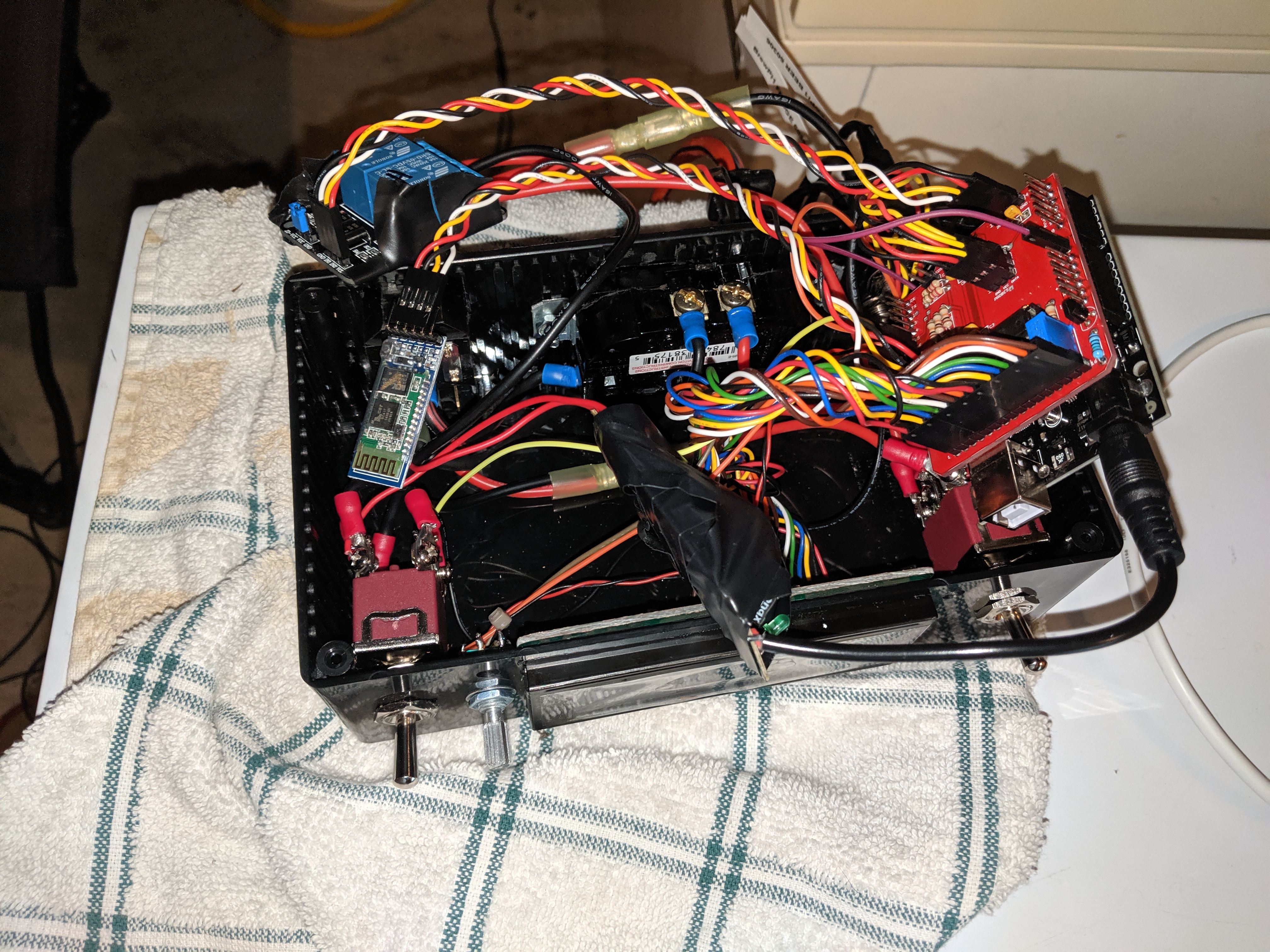
I forgot to take a pic last night but im using a project box like yours and damn..... i should have heeded your warning about it being a huge task to get everything to fit in there. I mean i did it, kinda, but is is PACKED! Im giving my self a win on this but it isnt too pretty in there. And i still havent wired the LEDs yea. Still trying to figure out how to mount them to the box. i have another one to build so im thinking of finding a bigger box to put this in.DAYAAAMMM!
Car Ramrod
Well-Known Member
- Joined
- Jan 24, 2019
- Messages
- 117
- Reaction score
- 16
Man if it is that straight forward im going to be so happy!! i might build my 2nd one in this box.I'm going from memory and it has been a couple of years, so cut me some slack if I remember this incorrectly, but...when I set one of my minions up via bluetooth, it was rather straightforward. Use the automated workflow and get your device working through the normal USB approach. Once it is connected and talking to the Fermentrack software, go through the steps to get the HC-05 programmed. Wire it to your board. Then go into the manage device/view logs tab for that device in Fermentrack and change the port from dev to whatever rfcomm port you assigned during the HC-05 setup when you bound it to the Pi. Should work as expected.
https://www.parts-express.com/parts-express-desktop-plastic-project-case-box-885-x-65-x-354--320-486
Car Ramrod
Well-Known Member
- Joined
- Jan 24, 2019
- Messages
- 117
- Reaction score
- 16
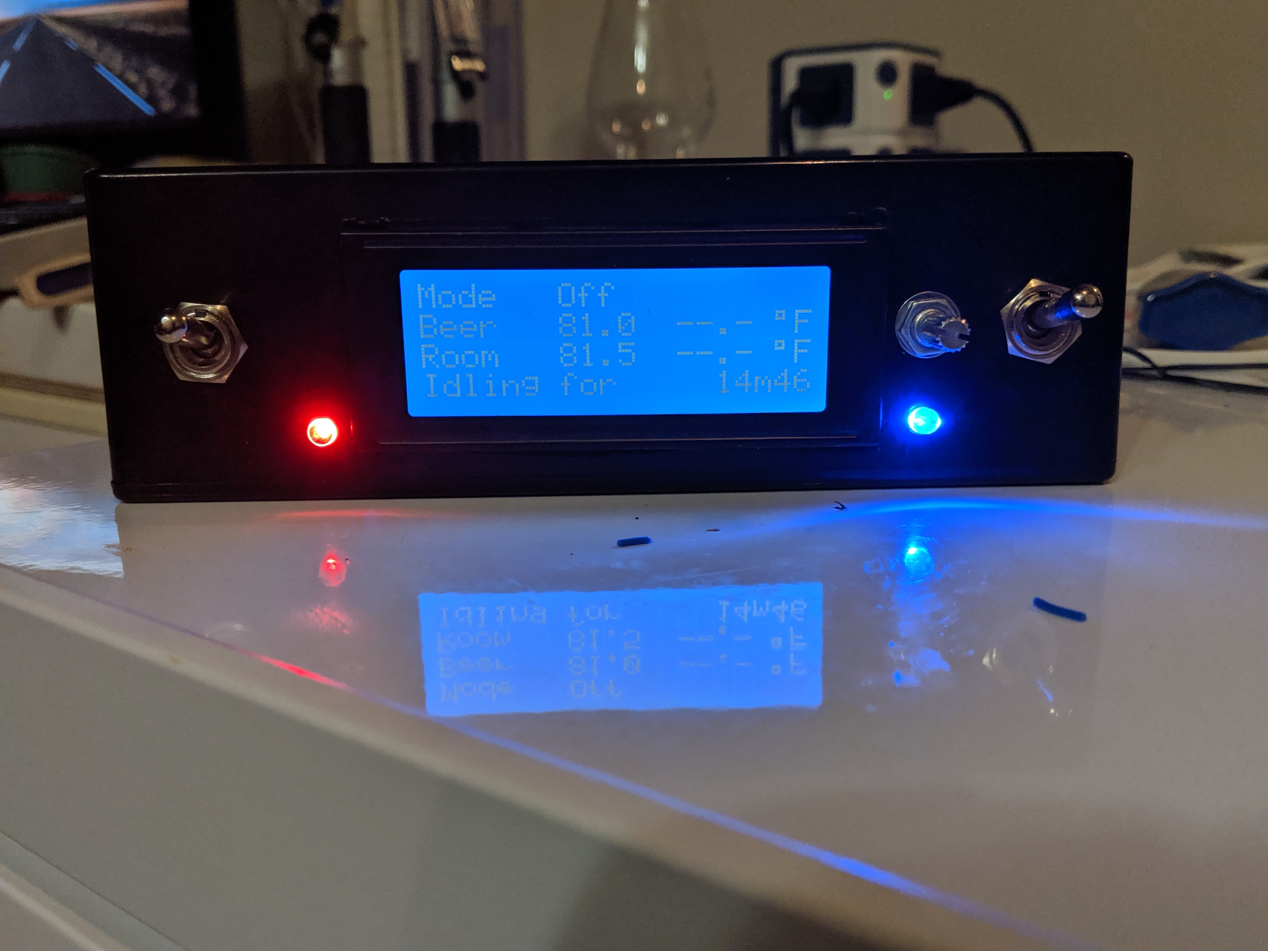
I am officially wireless with a HC-05. I followed LBussy's instructions for the HC-05. But i couldnt change the info in fermentrack (im gonna bring that up in the other thread) so i just deleted the device from fermentrack and reinstalled it to the serial port /dev/rfcomm# Now i need to finish my 2nd bluetooth minion then on to building one of @Thorrak 's esp wifi's for the kegerator out back. I feel so accomplished. Here is my 1st box. @day_trippr was right, stuffing all of this in that small box was a chore.
OP
OP
hahaha! Kudos on cramming all that in there!
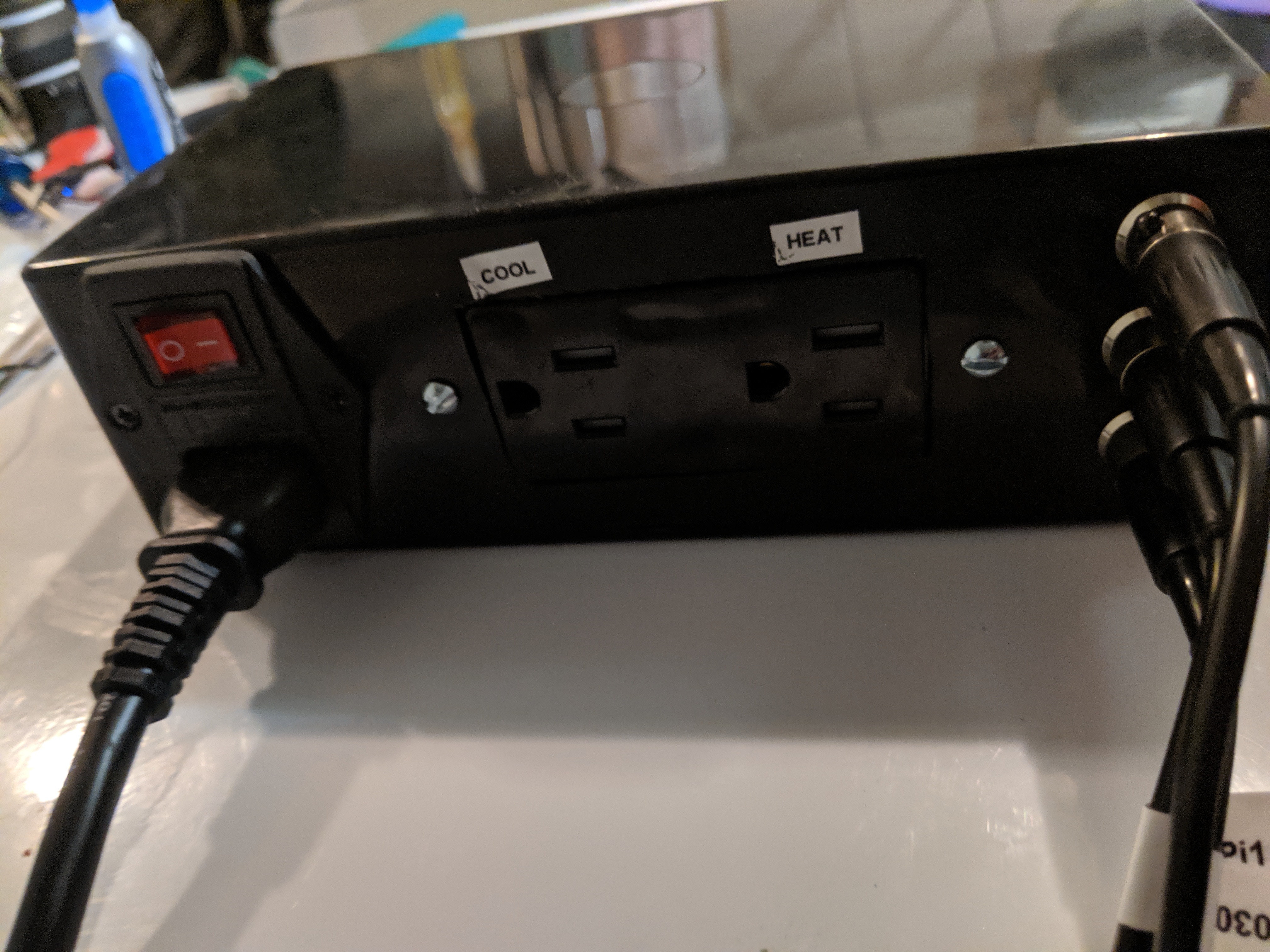
I see you used the same type of switched/fused/lighted AC bulkhead as I did. Note that while the bulkhead is rated for 10A the switch is likely rated for only 6A (which you can't determine without physically separating the switch module from the bulkhead).
Depending on the fridge/freezer you're controlling that switch may (will) eventually fry one or both poles. I ended up bypassing the switch on all four of my minions...
Cheers!
Car Ramrod
Well-Known Member
- Joined
- Jan 24, 2019
- Messages
- 117
- Reaction score
- 16
thank you it wasnt pleasant.
yea i thought it was a great idea to be able to unplug it where you could just move a box, and have a on off switch. I actually tried to re arrange the parts in there at first so it wasnt a "direct" copy of yours.
These are the ones i got. https://www.amazon.com/gp/product/B07B6JV52J/ref=ppx_yo_dt_b_asin_title_o09_s01?ie=UTF8&psc=1
It does say "Rocker Switch: Illuminated to show power status, 6A 250V AC 10A 125V AC." So we will see.
Also, mine isnt illuminating because i believe i dont have that wired. im guessing it has to do with the gold terminal.
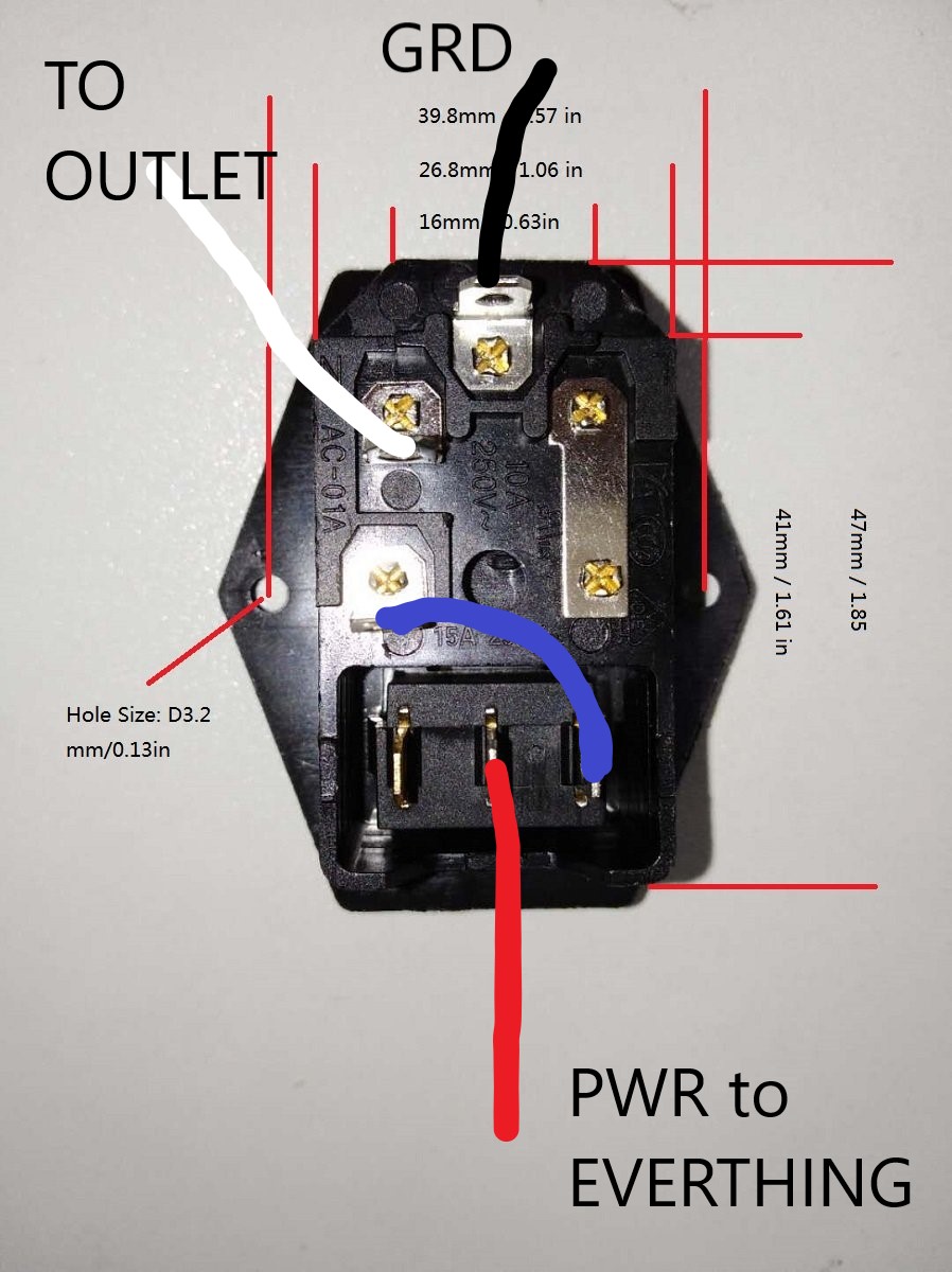
here is my wiring.
yea i thought it was a great idea to be able to unplug it where you could just move a box, and have a on off switch. I actually tried to re arrange the parts in there at first so it wasnt a "direct" copy of yours.
These are the ones i got. https://www.amazon.com/gp/product/B07B6JV52J/ref=ppx_yo_dt_b_asin_title_o09_s01?ie=UTF8&psc=1
It does say "Rocker Switch: Illuminated to show power status, 6A 250V AC 10A 125V AC." So we will see.
Also, mine isnt illuminating because i believe i dont have that wired. im guessing it has to do with the gold terminal.
here is my wiring.
Attachments
OP
OP
Hmm...that bulkhead is the same but the switch module is different. Mine are DPST with four pins, so both hot and neutral are switched through the module and the integrated lamp straddles (micro-neon, I presume) the "out" contacts.
If you have an ohmmeter you may be able to determine whether the third contact is for a neutral connection to light up the lamp...
Cheers!
If you have an ohmmeter you may be able to determine whether the third contact is for a neutral connection to light up the lamp...
Cheers!
Car Ramrod
Well-Known Member
- Joined
- Jan 24, 2019
- Messages
- 117
- Reaction score
- 16
i just read you need to conec the 3rd post to the neutral post.
OP
OP
There ya go
Similar threads
- Replies
- 12
- Views
- 4K
- Replies
- 7
- Views
- 2K
