How To: BrewPi LCD Add-On

Homebrew Talk - Beer, Wine, Mead, & Cider Brewing Discussion Forum

Help Support Homebrew Talk - Beer, Wine, Mead, & Cider Brewing Discussion Forum:

This site may earn a commission from merchant affiliate links, including eBay, Amazon, and others.
Ahhhhhhhhh I see! That makes MUCH more sense. I thought it seemed like a really convoluted way to wake the backlight! Very clever, I didn't realise there was that functionality (I haven't read the entire thread. Thanks again, day trippr.

Re: RE selection; is there a specific requirement? Adafruit have a nice 3 pin with built in push button, 24 pulse/segment.

https://core-electronics.com.au/rot...udWIzwQ5WiPCotjwM-lLbqKCLtMcW2wcaAmEwEALw_wcB
 
Ha yeah, it was more to check I was on the right track. First thing that came up on Google. I have to get some washers to finalise the case for the hardware, so I can pick one up locally.
 
Here's a link to a breakout board that makes it a tiny bit easier to connect that. If you don't want that, there's a link on that page to an encoder on Mouser.

Is there a way of ordering just one of each board, or a set of all 4 different boards, instead of 4 of each, or is that just a limitation of pcbs.io?

If you can only buy in 4s...... is there anyone in the UK who would want a set of them?
 
Those are so tiny I can’t imagine any of the PCB houses would sell a single. No, there’s no way of ordering one of each that I know of - unless you manually panelize and then you’re stuck having 4 of all of them.
 
OK - I've figured out enough to get myself to the point where I know I don't know enough to keep going, so it's time to seek some guidance.

First off, the amount of work you guys have put into this project is mind boggling. I've been lurking for a while and sifting through everything, and it's an amazing path from the first versions to the latest.

I'm looking at this as a learning project, so I'm generally trying to work out the logic behind everything as I go. I'm working on an Arduino shield (v 1.3.1a), along with the rotary encoder breakout (and eventually the Large Breakout Board) and a parallel LCD. I'm a little stuck - OK, a lot stuck. I'm good with the PCBs and I've got all the resistors and capacitors soldered in. Before I go any further, I want to double check what I'm doing with the remaining parts from the BOM. Can someone confirm the placement of the following items:

2N3906 PNP Transistor - Q1 (seems likely)
SN74HC595N 8-Bit Shift Register - ??
16-pin IC Socket - ??

I'm guessing that the shift register and IC socket go into U1 in the board, but not sure in what order - presumably the socket goes first and is soldered in, then the shift register inserted into the socket?

As to connecting the LCD - am I correct that I need 2 6-wire ribbon cables (or similar solution) to run from the shield to the LCD?

I think that's it (for the moment). I've been digging around these threads for a couple of weeks, and it's a little overwhelming.

Thanks in advance for any help - sorry if these are pretty basic!

Tom
 
im having a bit of trouble w/ the pcbs.io website not being able to process my payment for the pcb boards, so im wondering if i could just take the EAGLE file(s) from the github and get these boards through another manufacturer (i.e., the OSHPark website mentioned earlier in this thread). if i understand this correctly, the EAGLE files have the .brd extension? also, am i correct in assuming that a two-layer pcb refers to tracing on both side of the board?
 
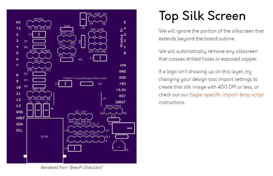
alright perfect, thank you! the images looked correct on OSHPark (aside from the missing brewpi remix logo on the silkscreen of the arduino uno protoboard). really excited to try and wrangle this thing together.
 
the images looked correct on OSHPark (aside from the missing brewpi remix logo on the silkscreen of the arduino uno protoboard).
That's what concerns me. I just uploaded the current one and this is what I see:

1603283268591.png

Not sure why you are not getting a logo on the silkscreen.
 
that's what it shows for me as well. i should've specified that it doesn't show the logo when i go to the next step where it breaks the board down further (under the 'top silkscreen' section). this is what i'm getting there:

Capture.JPG

i just figured the last paragraph explained it, maybe 400 DPI? idk.
 
That's weird. I know it's on the purple boards I have here. I can't say for certain it will show up when you receive it, but if not, it's just cosmetic.

The image is on layer 25 with the names.
 
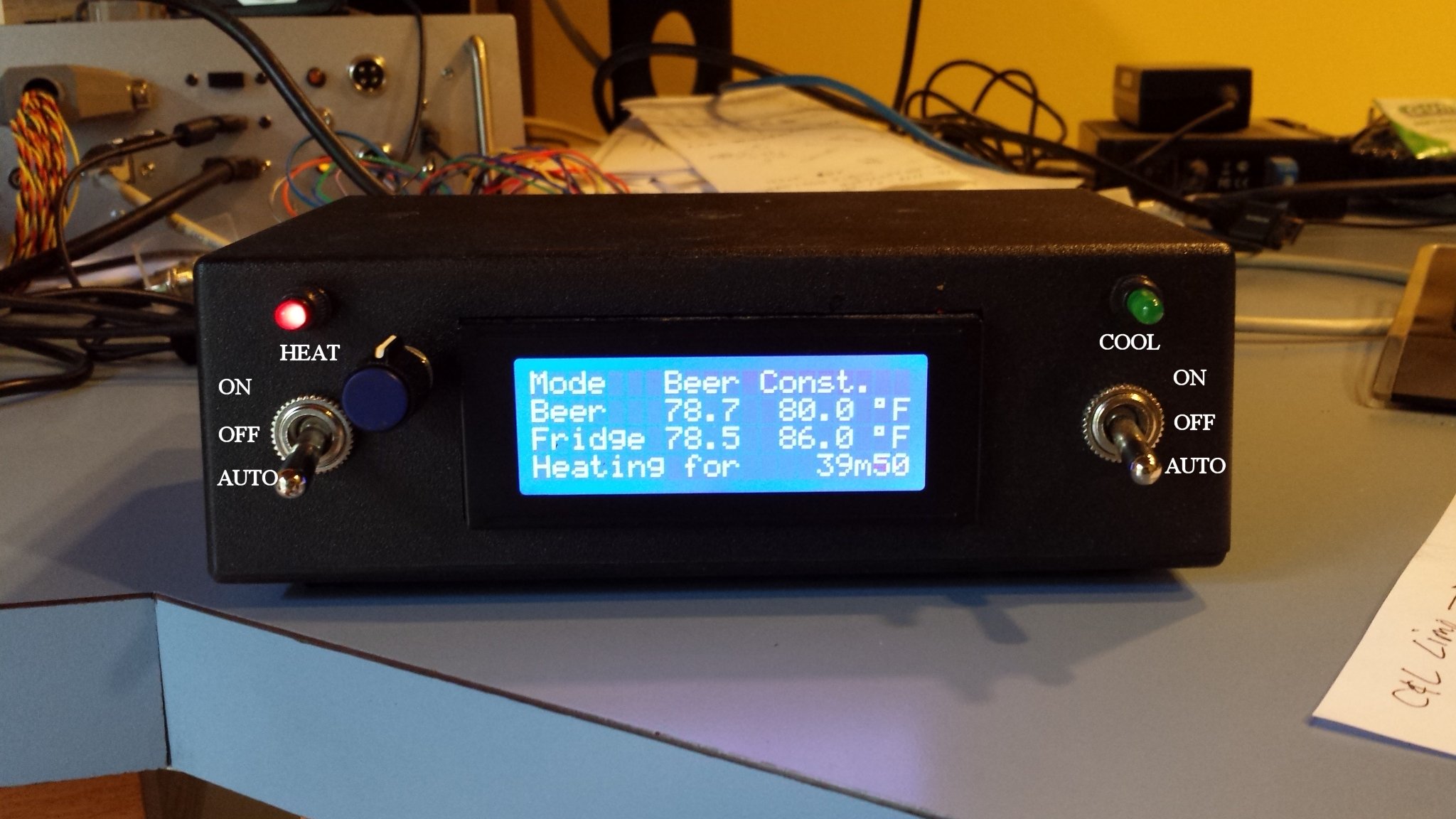
well i got the boards a week ago and fwiw the silkscreen matched up exactly! i got it soldered up over the weekend and everything seems to be working fine on the low voltage side after some testing. however, im having an issue with a few characters on the lcd screen not displaying (upper right corner, where the fridge temp is displayed). i figure its probably just a bad connection with the pin headers on the lcd board? when i flex the board at the top, i can get the characters to display correctly so i doubt that it has to do with anything on the brewpi board or software side.

i was also wondering if there is a good solution to making the temp sensors modular to the project box. is there an rj connector that could work for this or some sort of three pin connector?
 
If there are characters that go in and out by flexing the display, it's a display module issue, nothing to do with BrewPi or the shield.
I had an LCD that did that in the bottom left corner. Got it replaced.

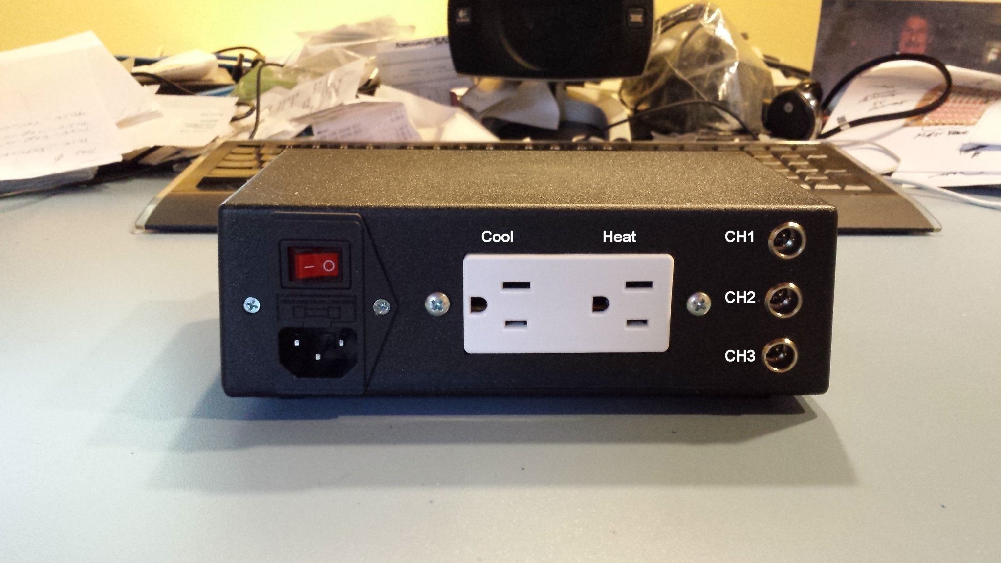
As for connectors, here's the back and front of one of my BrewPi Bluetooth "minions". I use 3 pin "Tiny XLR" connectors extensively in my brewery and used them here for the sensor ports...

brewpi_satellite_02.jpg


minion_upgrade_02.jpg


Since those pics were shot I've upgraded all of my minions with a hardware reset button...

minion_mk3_02.jpg


Cheers!
 
i was also wondering if there is a good solution to making the temp sensors modular to the project box. is there an rj connector that could work for this or some sort of three pin connector?
The current board does have an RJ45 connection (which Dave doesn't like too much) and there's a matching breakout board for the sensors. I'd forgotten to upload the design - will do so here shortly.
 
i was also wondering if there is a good solution to making the temp sensors modular to the project box. is there an rj connector that could work for this or some sort of three pin connector?
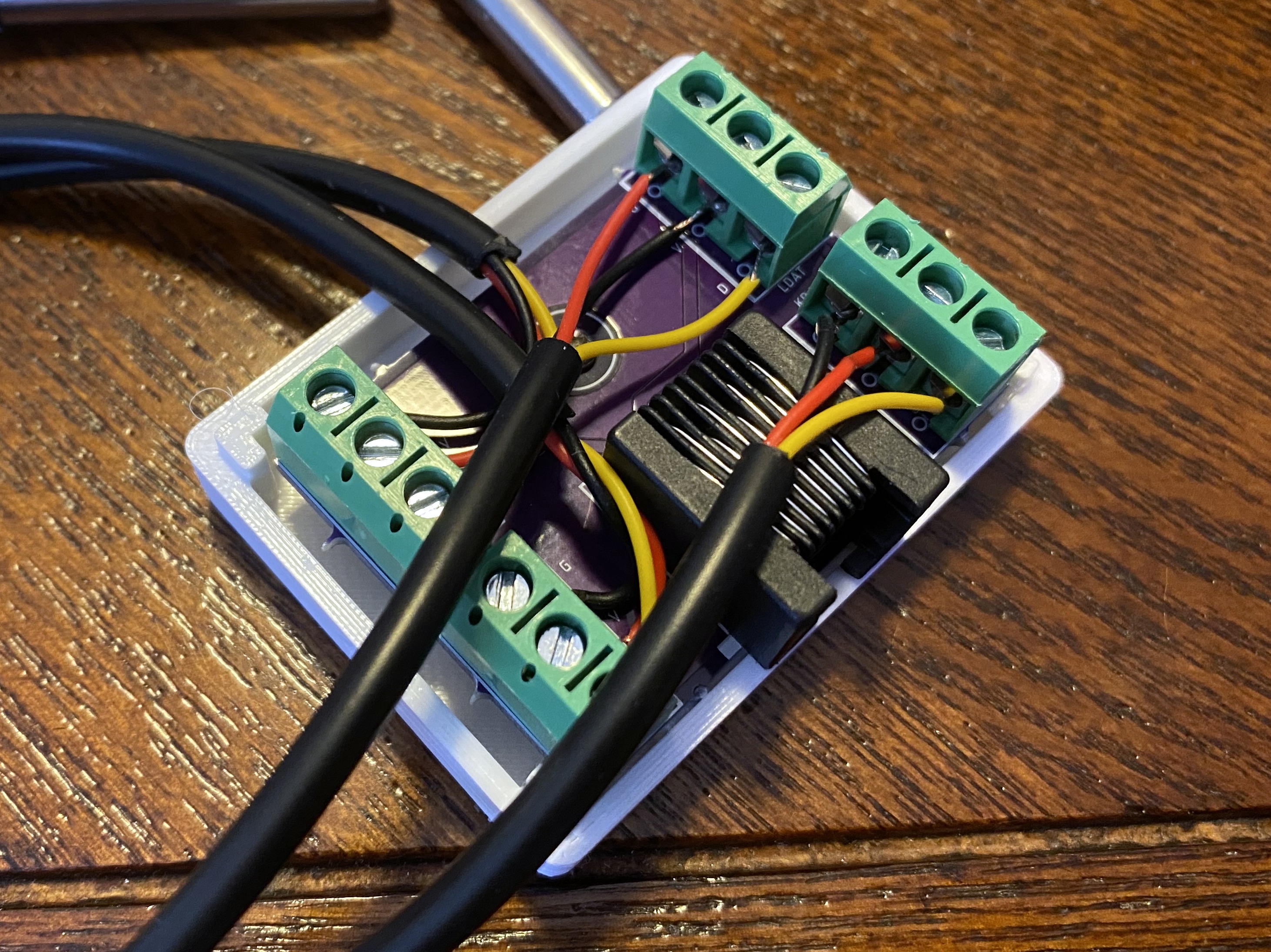
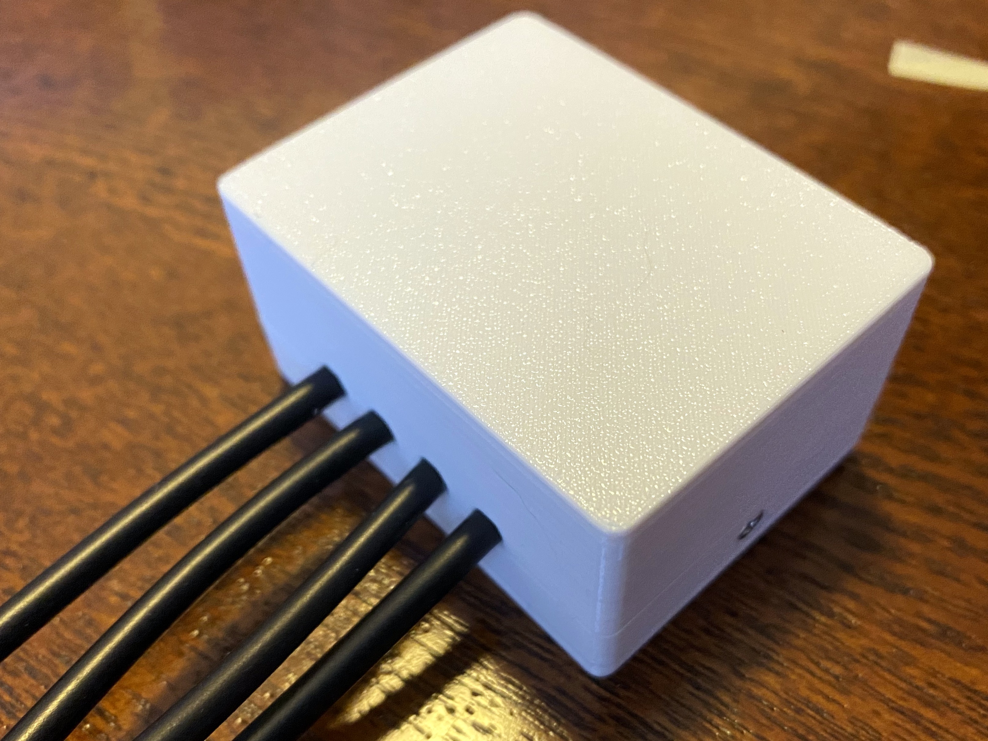
Okay, here's the breakout board. Note that the ordering link there does not work yet, most of the links are still dead. This breakout is designed to connect with a straight Ethernet cable and will support up to three sensors + a door switch connection. The idea being you run one cable into the fridge and connect your senors there via the three-pin screw connectors. Optionally, you can use one of these two-pin screw connectors for a door switch. The wires run to the inside, and out the end. A model of a case is included which can be 3-D printed to facilitate a setup as shown here:

IMG_0114.jpg


IMG_0115.jpg
 
Admittedly I'm not a huge fan of rj style connectors inside a keezer/kegerator, but I already had a small fleet of minions with Tiny XLRs running by the time I worked with @CadiBrewer on his first gen shield :)

Cheers!
 
Thanks for the quick replies!

If there are characters that go in and out by flexing the display, it's a display module issue, nothing to do with BrewPi or the shield.
I had an LCD that did that in the bottom left corner. Got it replaced.

I was worried it was the display module, good to know! Looks like I'll have to order another one then. I really like the look of those XLR connectors. You say you're not a fan of the rj connectors inside of a keezer/kegerator, is that due to corrosion concerns?

Okay, here's the breakout board. Note that the ordering link there does not work yet, most of the links are still dead. This breakout is designed to connect with a straight Ethernet cable and will support up to three sensors + a door switch connection. The idea being you run one cable into the fridge and connect your senors there via the three-pin screw connectors. Optionally, you can use one of these two-pin screw connectors for a door switch. The wires run to the inside, and out the end. A model of a case is included which can be 3-D printed to facilitate a setup as shown here:

Ah, I must've overlooked this board. Probably a lot easier to mess with this than trying to solder wires onto XLR connectors, looks easier to replace as well. I soldered the leads of one of my temp sensors to female dupoint wires to test it and, with my dodgy soldering skills, I'd rather stay away from doing that if I can.

So I assume that i'll need two of the rj45 connectors, one on the brewpi shield and another on this one? I'm also not too familiar with 3D printing. Would I simply upload the .stl files to an online 3D printing service, much like the boards?
 
I really like the look of those XLR connectors. You say you're not a fan of the rj connectors inside of a keezer/kegerator, is that due to corrosion concerns?
They are nice, but I find them to be fairly pricey. The RJ45 is certainly not as robust, but in the right application, I think they work fine.
Ah, I must've overlooked this board.
No, I just uploaded it. I had it done, just not uploaded. I refined that as part of a different project and forgot to add it.
Probably a lot easier to mess with this than trying to solder wires onto XLR connectors
I think it's more convenient and modular, yes.
I soldered the leads of one of my temp sensors to female dupoint wires to test it and, with my dodgy soldering skills, I'd rather stay away from doing that if I can.
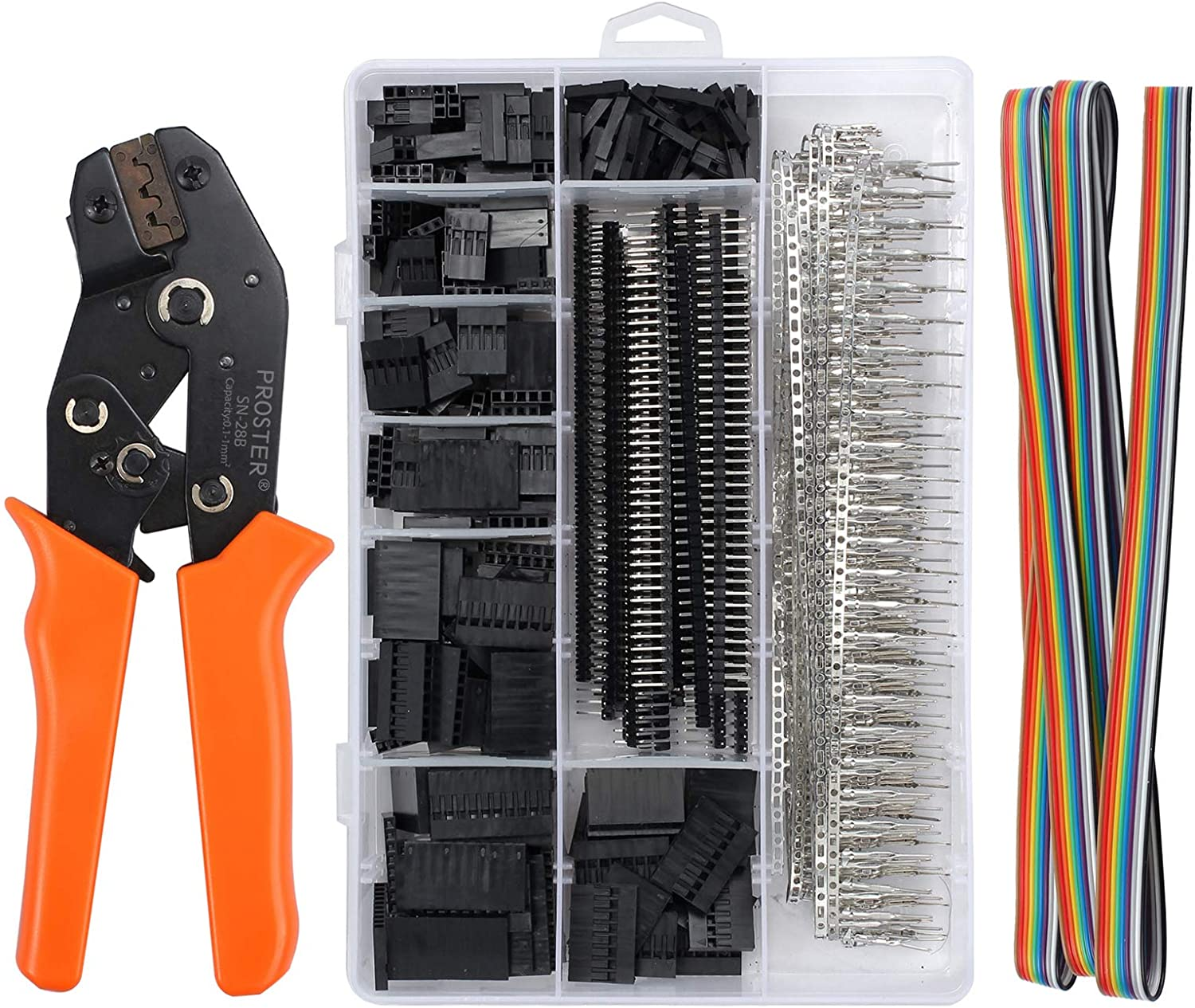
I have one of these:
1605012661085.png

Dupont Crimper Set - $29.99 with Prime Shipping @ Amazon

I find it VERY handy to have around for these projects. That said, I got away without having one for a long time. It takes effing up a few of these to get the hang of the crimps, but after that it's not bad.
So I assume that i'll need two of the rj45 connectors, one on the brewpi shield and another on this one?
Yep. I think the link for that is active - buying a bag of them from China is cheapest.
I'm also not too familiar with 3D printing. Would I simply upload the .stl files to an online 3D printing service, much like the boards?
Yes, you can. Depending where you live (your profile is not filled out) you may be able to get someone to print one for you. You'll also need a couple of M2x5mm Flat/Countersunk Head screws to close that box, and a single M2 Round/Pan Head Machine screw to secure the board in the box.. I find using a zip-tie around the cables inside the box (not attached to anything other than the single cable) helps provide strain relief.

Another thing you might like while you are getting something 3D printed is this DS18B20 Probe Holder. That plus a little double-stick tape (also handy to mount the probe breakout) is a nice way to mount the fridge probe.
 
very nice, just ordered a set of the breakout boards! quick question about the components you have listed on the github page. the minimum quantity listed on aliexpress for the 2/3 terminal blocks are 100pcs/50pcs respectively. is that right? it makes me kind of uncomfortable purchasing such a large quantity of these, but i guess that's just the market of electronic components.

if i didn't already have a ton of dupoint wires id love to get that crimper set, especially with those multiheader connections. i live in a small town in Ohio, i believe my local university has 3D printing capabilities so i could probably contact someone who could help with that.

thanks again for the help! like tomakana mentioned above, im also using this as somewhat of a learning experience and would just like to mention that the time and expertise you guys have put into this is astonishing!
 
the minimum quantity listed on aliexpress for the 2/3 terminal blocks are 100pcs/50pcs respectively. is that right? it makes me kind of uncomfortable purchasing such a large quantity of these, but i guess that's just the market of electronic components.
You can get smaller quantities on Amazon for instance, but it's about the same price. If you just accept the fact that you will make mistakes, and this is a gateway drug anyway, you might as well get extra. :)
if i didn't already have a ton of dupoint wires id love to get that crimper set, especially with those multiheader connections.
1605190864136.png


There is no saving money here. There's just learning and growing.
 
i just wired up a new LCD screen, everything is looking good so far and the breakout board is on its way! just wanted to double check, are the correct dimensions for the (top) 3d case 55.00 x 42.00 x 24.60 mm? you have the board dimensions as 17.88 x 25.58mm and your picture doesn't quite seem to match this.
 
If you are referring to the Sensor enclosure in the post from @LBussy , you have the dimensions of that correct. The breakout board dimensions that were used in designing it are 33.30 x 45.8. I'm not sure which board you are referring to that has those dimensions.
 
i just wired up a new LCD screen, everything is looking good so far and the breakout board is on its way! just wanted to double check, are the correct dimensions for the (top) 3d case 55.00 x 42.00 x 24.60 mm? you have the board dimensions as 17.88 x 25.58mm and your picture doesn't quite seem to match this.
The board I have here, and the one you referenced in this post, is 53.9 x 61.3mm. Donnie designed the case, so if he says those dimensions are correct, they are. :)
 
yeah i was talking about the rj-45 sensor breakout board, the dimensions listed on the github page underneath the 'Order from...' header are 17.88x25.58mm. it looks like these are the dimensions for the rotary encoder board so that must've just been a typo. glancing at my order receipt for the board, the dimensions are the same as @gromitdj mentioned. all good!
 
im having a bit of trouble w/ the pcbs.io website not being able to process my payment for the pcb boards, so im wondering if i could just take the EAGLE file(s) from the github and get these boards through another manufacturer (i.e., the OSHPark website mentioned earlier in this thread). if i understand this correctly, the EAGLE files have the .brd extension? also, am i correct in assuming that a two-layer pcb refers to tracing on both side of the board?

did exactly this... same issue with payments, even via bitcoin. So went looking and OSHPark ended up being the one I ordered from.
 
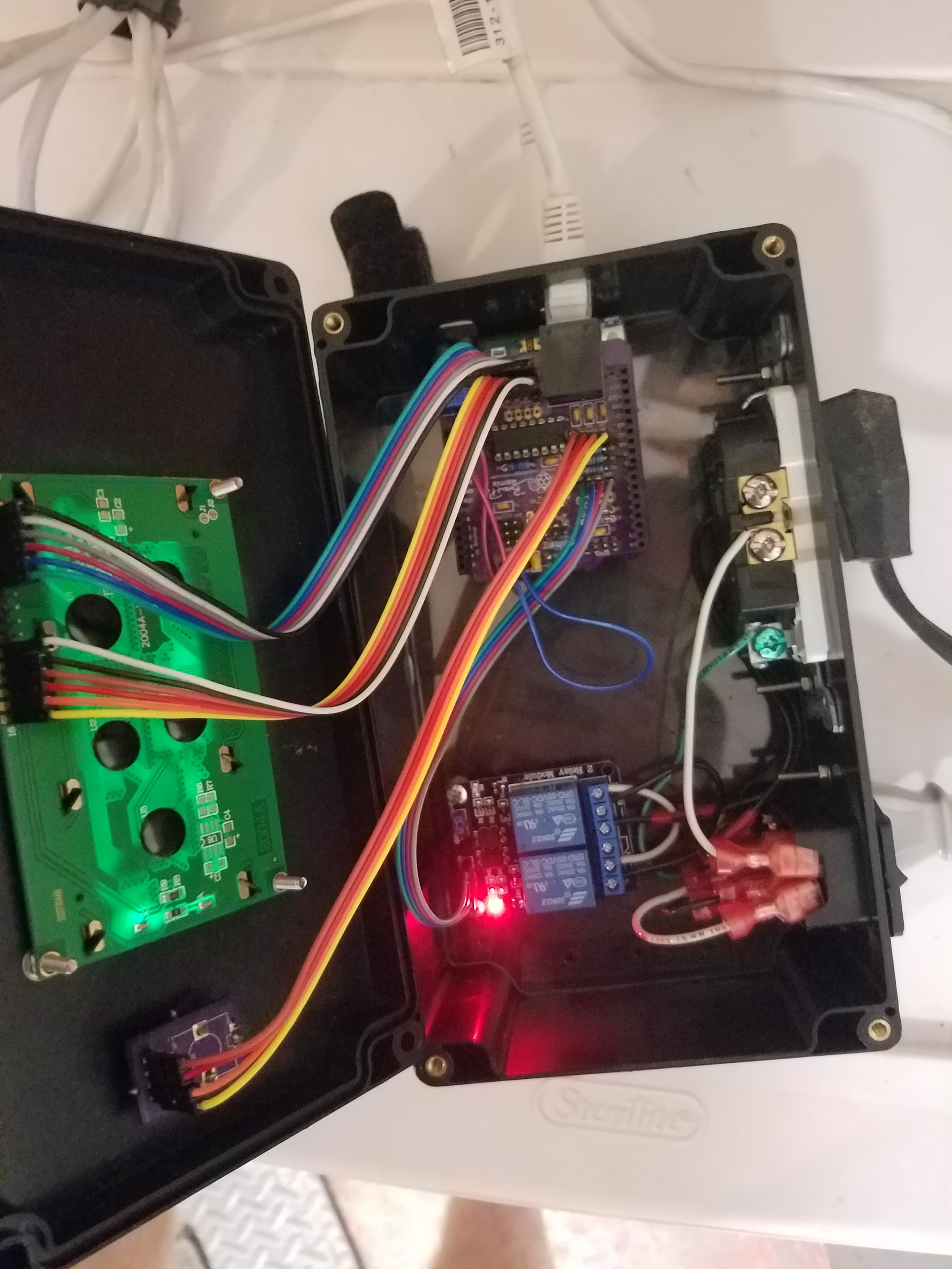
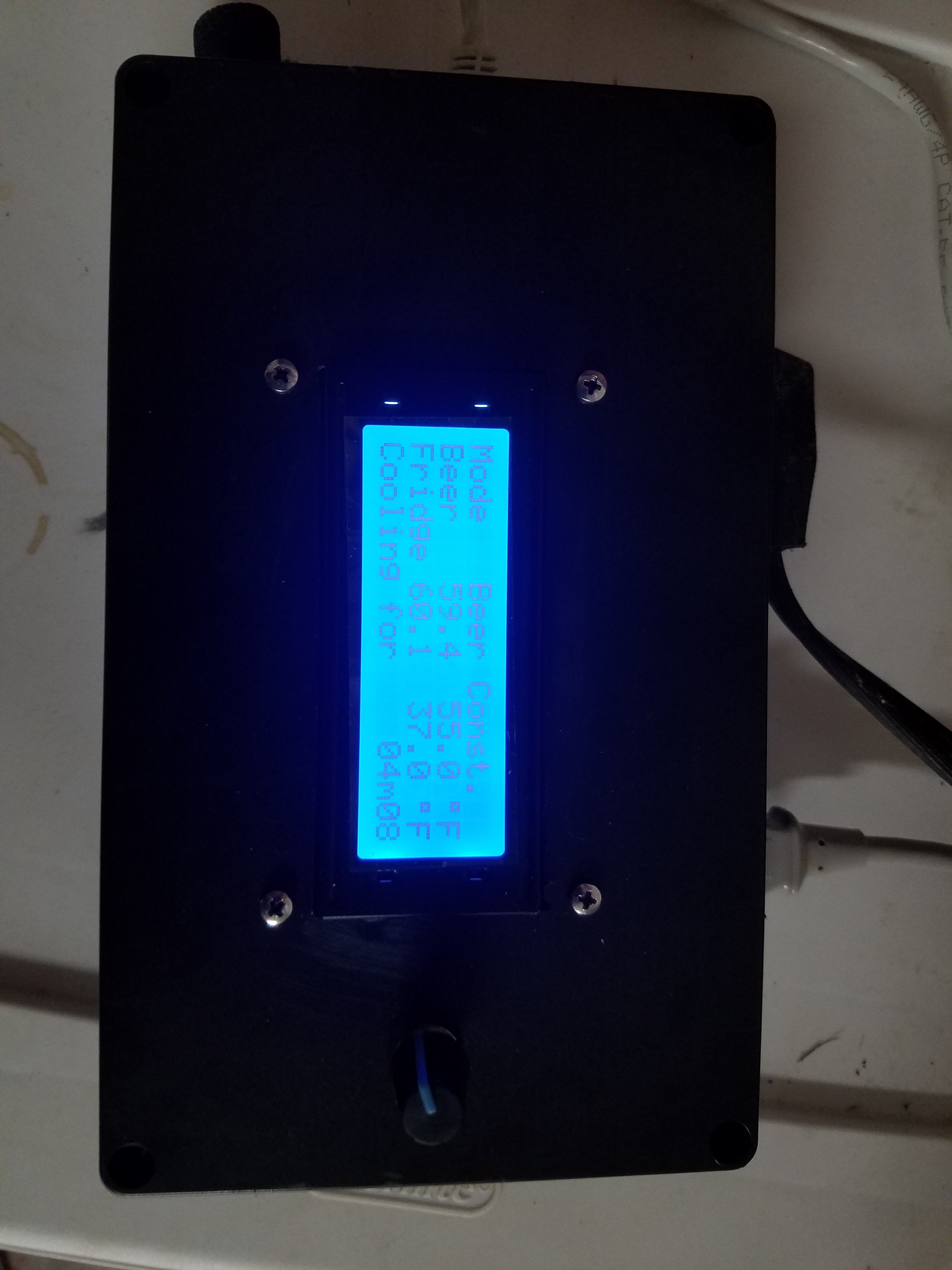
Finally got it all assembled, mounting was way more challenging than i thought it would be. Would probably do a 3d printed case next time. Still waiting on the case for the temperature probe breakout board. Quick question, is it safe to heat to upwards of 100F (say for saison/kviek strains)? My basement doesn't get much past 68F, so I was hoping I could use this to ferment on the warmer end.
20210124_153254.jpg
20210124_153242.jpg
 
is it safe to heat to upwards of 100F (say for saison/kviek strains)?
There's nothing about BrewPi Remix that will make that unsafe. Assuming your high voltage wiring is all legit, it will maintain any temp you set. Remember you will have to change the max temp to get there - out of the box it's set at 82 IIRC.
 
awesome, really excited to ferment my first batch with this! ive got a bam biere clone in the works so im gonna need to get it a wee bit hotter. thanks guys!
 
Back
Top