CadiBrewer
Well-Known Member
V1.2 boards are fabbed and on the slow plane from China. V2.0 boards should be sent to the board house tonight.

V1.2 boards are fabbed and on the slow plane from China. V2.0 boards should be sent to the board house tonight.
Can you post the link for the eagle files pleaseV2.0 board done and ordered up. In 4 to 100 short weeks, it should arrive.


![Craft A Brew - Safale S-04 Dry Yeast - Fermentis - English Ale Dry Yeast - For English and American Ales and Hard Apple Ciders - Ingredients for Home Brewing - Beer Making Supplies - [1 Pack]](https://m.media-amazon.com/images/I/41fVGNh6JfL._SL500_.jpg)


Can you post the link for the eagle files please
I know better than to be on the leading than the Bleeding edge of technology. I pulled up the brd in eagle and noticed that there might be an error with the text at the spot the Nano is on the board. Did you go with DirtyPCBs for your boards?No problem at all. All three versions can be found here:
https://drive.google.com/drive/folders/0BwakCoACNDsmSWNQeS0xNVBBRFk?usp=sharing
That being said, I'd wait before ordering them until I have a chance to solder one up for testing. I'd hate to have someone waste $25 on a batch of boards and the components only to have them not work. But the files are yours to do with what you will.
I know better than to be on the leading than the Bleeding edge of technology. I pulled up the brd in eagle and noticed that there might be an error with the text at the spot the Nano is on the board. Did you go with DirtyPCBs for your boards?
I don't know what he's looking at, but I'm seeing some rats! (unrouted connections).
Pull the board up and change the unrouted connections to something more visible - like that hot pink color - and they'll stand out better.
There's a missing 5V connection to R3-R5, a missing GND connection to the Encoder header, and a missing GND connection to C1 and the LCD header pins and the shift register pin 8.
My apologies for missing it earlier, that goldish color just doesn't show up well enough to spot.
Cheers!
[edit] Also you have the net at J1.1 named "TX" which is also the name of the net from the Arduino to the resistor divider. That's causing an Unconnect rat across both pins of R7 that shouldn't exist, Rename the net at J1.1 to something else.
What software are you using? Doesn't it have LVS (layout versus schematic) to catch this sort of thing?
What software are you using? Doesn't it have LVS (layout versus schematic) to catch this sort of thing?


It's not tested yet ... when it is we'll release it. The new box is printing. I should know whether it's good tomorrow.Nice you got a Thingiverse link?
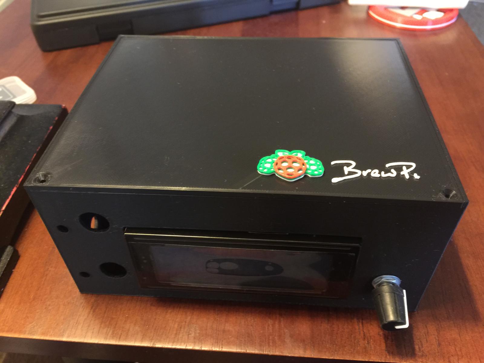
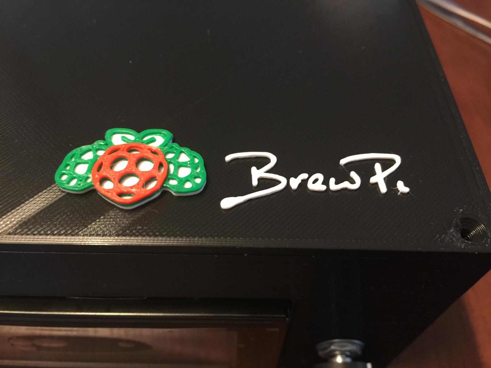
Here's a pic of the latest print.It's not tested yet ... when it is we'll release it. The new box is printing. I should know whether it's good tomorrow.


Needs a couple of meatballs.Wow. That looks really, really good!
And I just realized I haven't eaten anything all day
Here's a pic of the latest print.

(For those of you not familiar with 3-D printing and how it can go wrong, suffice it to say I screwed up.)
It's re-printing. I should have a verifiable print tomorrow and then I'll post the .STL files.
Can you remelt your mistakes and make new filament?Nice, I've made a few just like that before. lol.
A roll of filament is anywhere from $15 - $45 for a kilo. It takes about 150 grams to print a case so the material cost is low. Time-wise, it's four hours for the lid and 15 for the case. 3D printing is not fast. I looked on 3DHubs and it should cost from $25 on up to have this done.Can you remelt your mistakes and make new filament?
Donnie is doing the modeling and I'm doing the kibitzing and printing. Some of the things don't have models, some don't even have proper measurements. Case in point: I ordered some LED bezels that claimed to need a 7.1mm mounting hole. When I actually had some in hand they were 5.7mm. If I had actually purchased the parts first (and had them in hand) we'd be done by now.If your cad software has the ability to bring in models of physical parts to work with you should be able to test fit the parts into the holes. if you can't find a proper part rendered you can always mock one up
How about inserting a 3mm hole in the model (which would accept a 3mm LED without a bezel), and then using hand tools to open up the hole to accept 5mm LEDs or arbitrary-sized bezels/housings? The 3mm hole would be a good pilot hole for larger drill bits.
V1.2 boards are fabbed and on the slow plane from China. V2.0 boards should be sent to the board house tonight.
If you have extras of the 1.2 boards when they arrive please add me to your list.
I'd take 2
Thanks I'm just trying to gather my parts.
Correct.
