• Please visit and share your knowledge at our sister communities:
  • If you have not, please join our official Homebrewing Facebook Group!

    Homebrewing Facebook Group

How To: BrewPi LCD Add-On

Homebrew Talk

Help Support Homebrew Talk:

This site may earn a commission from merchant affiliate links, including eBay, Amazon, and others.
I'm fortunately to have an old-school e-hobby store a half hour away, and they carry pretty near every imaginable diameter of shrink wrap tubing.
I picked up a chunk that was wide enough to insert the guts of a $2 eBay 9V 1A wart, shrunk it snug, and hard-wired it inside my wee minion case.
The volumetric difference is dramatic - I literally could not have added the LCDs to my minions if I kept the wall wart cases intact.

You could use electrical tape as well - it's not like there's a lot of heat going on inside one of these things, so it should stay wrapped...

Cheers!

I'll keep that in mind. Depending on the enclosure, I thought of using the casing, but that sounds like a better solution.
 
Very close. The LCD came out of reset and is waiting for a command.
Verify the power/gnd to the shift register, then trace the GPIO path to the shift register, then the shift register outputs to the LCD reg select, enable/clock and data pins...

Cheers!
 
Rotary encoder wired in and working!

I have used the rotary encoder to change to beer constant to heat and cool and the relay has clicked several times without scrambling.

Now to find a box and test it under load.
 
You da man! :mug:

I did miss one of the wires on the underside. :mug:

I also pushed some solder where I though there may be contact across pads that shouldn't be connected. (my soldering is a little agricultural and I am NOT putting up a photo of that!)
 
I did miss one of the wires on the underside. :mug:

I also pushed some solder where I though there may be contact across pads that shouldn't be connected. (my soldering is a little agricultural and I am NOT putting up a photo of that!)

Awesome. I have had a scrambling issue for awhile not and appears to be a result of the relays. Probably my soldering and a not so great connection here and there. Only way I reset screen is unplug USB from power and back on quickly. Not what I want to do as this resets the brewpi intermittently.

I haven't visited this thread in awhile, so curious as to what schematic you used, and parts, etc, to get your setup working without a hitch. Cheers!
 
Awesome. I have had a scrambling issue for awhile not and appears to be a result of the relays. Probably my soldering and a not so great connection here and there. Only way I reset screen is unplug USB from power and back on quickly. Not what I want to do as this resets the brewpi intermittently.

I would figure out a way to power the Pi separately or make sure to follow the shutdown procedure on the Pi. Too many attempts at pulling the plug is going to zap the SD card sooner or later. And probably when you need it the most.
 
Awesome. I have had a scrambling issue for awhile not and appears to be a result of the relays. Probably my soldering and a not so great connection here and there. Only way I reset screen is unplug USB from power and back on quickly. Not what I want to do as this resets the brewpi intermittently.

I haven't visited this thread in awhile, so curious as to what schematic you used, and parts, etc, to get your setup working without a hitch. Cheers!

I used the instruction on page 44 of the post.

The only difference being cheap Chinese Uno clone, cheap Chinese prototyping board which is slightly different layout to Sainsmart. I also used cheap Chinese relay.

I also did the wifi option using a wemos D1 (not Mini) clone and followed the wifi thread instructions.
 
It's been running stable for a couple of days. I randomly set beer constant mode on and off with the rotary encoder to kick the heat or cool relays on and off. No scrambling so far.
 
I ended up with a dead SD card from so many power cycles of the rPi. Got anew one, and re-loaded everything. Running fine, but scrambling again. "Power UNO from a separate 5V connection" Is this not how the UNO is powered though from the rPI, via the power from the USB connection needed for communication?

I would like to put this issue to bed, perhaps having the automatic LCD reset in the code? Or try the easiest route which may be the separate power source, however I am confused as to where the would connect on the UNO board.

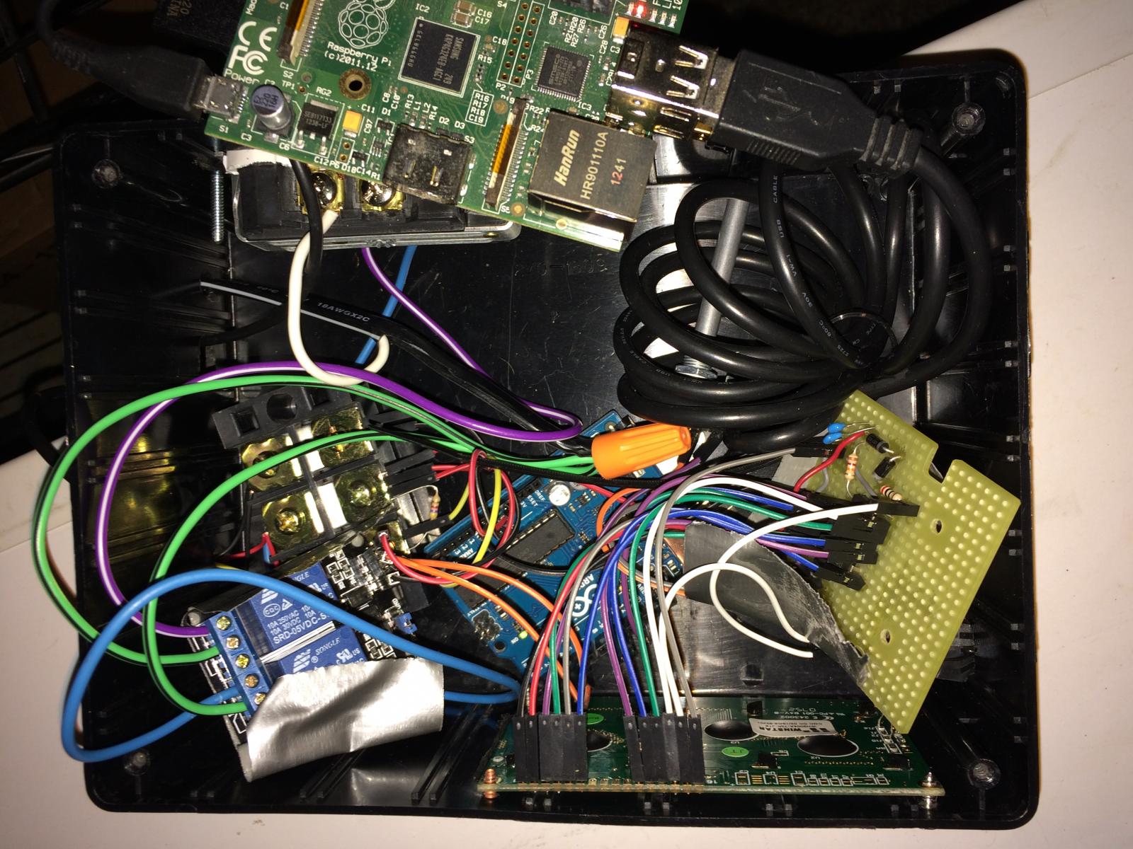
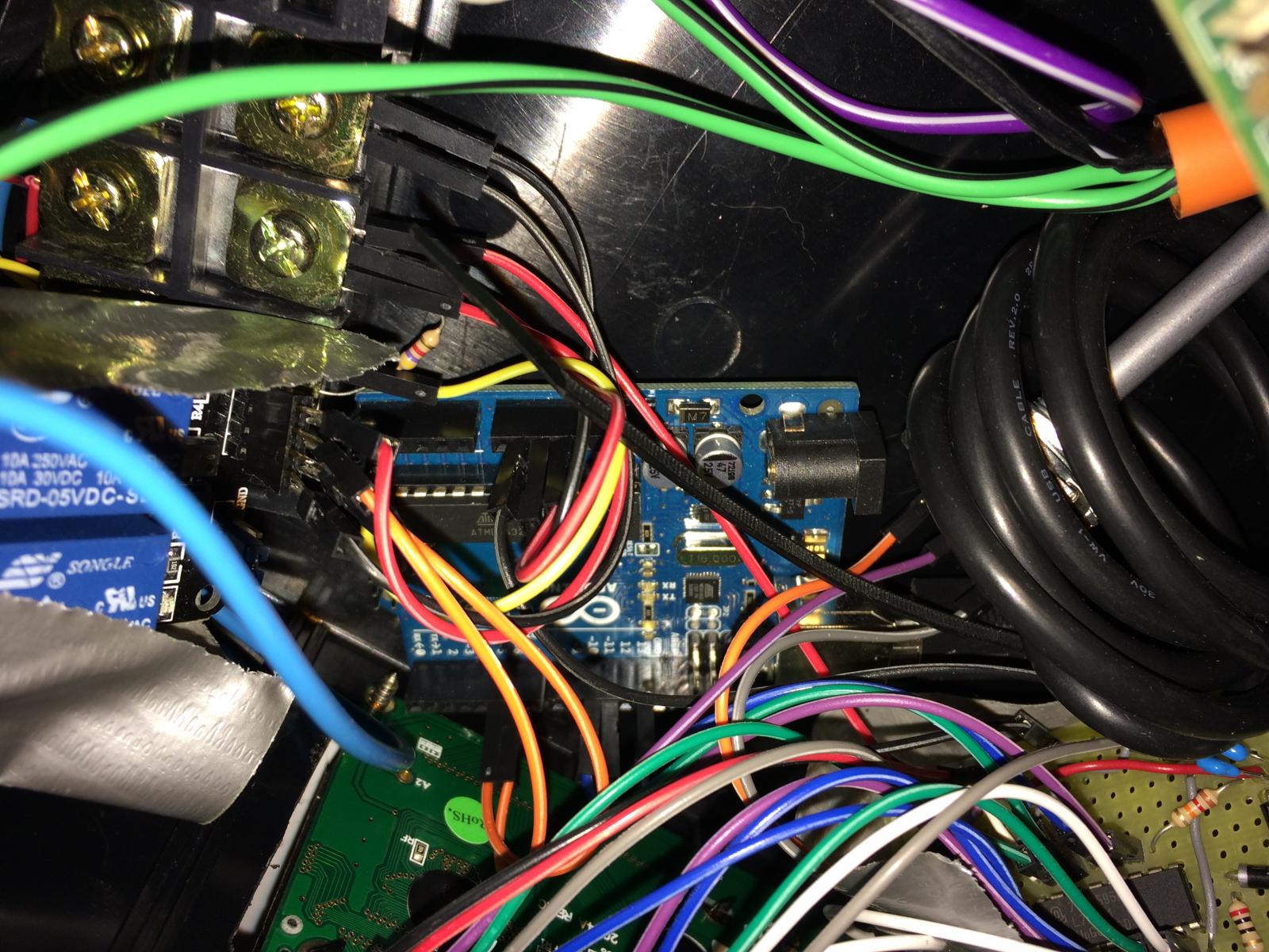
FYIW, here are 2 photos, can provide more if needed.

IMG_3768.jpg


IMG_3769.jpg
 
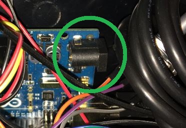
And I think I just answered my own question... power UNO here (see green circle in pic)? I knew it was too early today....

Are there PINs I need to take out from UNO or change a connection (USB) from the rPi to UNO?

Capture.JPG
 
And I think I just answered my own question... power UNO here (see green circle in pic)? I knew it was too early today....

Are there PINs I need to take out from UNO or change a connection (USB) from the rPi to UNO?

You beat me to it...

06.JPG

No changes necessary. When you power the Uno with a separate supply, it automatically switches over to that power supply and stops grabbing power from the USB.
 
Okay, now I'm guessing my UNO supply may not be sufficient enough, it's rated output i 5V, 2.5A.... whereas my rPi is 5V, 700mA.

Will the rPi still deliver power since my UNO supply is under the voltage input required?


Powered up, screen on... no loads just yet, so waiting game at this point.
 
Are you saying your Pi power cycles on it's own? If so that's more than likely a different issue. If you mean you have been power cycling it to fix an LCD scramble then the issue is you mistreating it - you should never tank the Pi. You should issue the shutdown or reboot command when needed. If you need to power cycle the Uno you can hit the reset button, or pull the USB and plug it back in.

The Uno will automatically switch to the external power supply if the voltage exceeds that of the USB voltage (actually if it exceeds something like 7.5V). Therefore you should use a 9V power supply. If you externally power the Uno but still have it connected to the Pi (as we would) it will not power cycle when you pull the power, you would have to pull both.
 
I was manually power cycling the Pi to correct my scramble, however I eventually croaked my SD card in doing so.

I will need to get a larger power supply for the UNO then, the 5V (2.5A) one I just started using about 10 minutes ago will not be sufficient enough, and I suspect another scramble in the near future when the load kicks in.
 
I was manually power cycling the Pi to correct my scramble, however I eventually croaked my SD card in doing so.
Yeah that's a nuclear option and as you learned, no bueno. You can safely unplug just the USB (if you can reach it).

I will need to get a larger power supply for the UNO then, the 5V (2.5A) one I just started using about 10 minutes ago will not be sufficient enough, and I suspect another scramble in the near future when the load kicks in.
I'm not sure what relays you are using, but I am using the 2.5A for the Pi and the Pi is powering the Uno and it's fine. The scramble does not seem to be related to low amperage although that's a possibility I guess if you were significantly lower than needed. The 2.5A should be more than enough but you need 9V if you are going to power the Uno separately.
 
Received the 9V/1A power supply today. Hooked up and running. I feel now I am in the same boat as this screen with the solid 2 rows of blocks. One thing I did notice was solid steady state of illuminance during powering up cycle. Before when running power from the rPi, I would notice the illuminance sort of flicker during the powering up cycle.

Now since I am on the separate power source for UNO, should I have an additional ground somewhere?
 
If your Uno is cabled via USB there's already a common reference.
If you were to use a serial connection instead (only god knows why ;)) then you'd need to strap the grounds together...

I feel now I am in the same boat as this screen with the solid 2 rows of blocks.

Color me confused: is the LCD working properly or not?
All of my LCDs power-up with two rows of white squares...

Cheers!
 
Oh the serial data connections. Those were the days to program huge LED displays.

Screen powering up as it did in the past however it remains with the 2 rows of blocks. On a side note, previously when running power from rPi, this would happen but then eventually go to displaying the temperatures. Now when running from separate power source I do not get past the blocks. Wondering if I bumped a connection or one became loose.
 
Hi folks. I've got my BrewPi's up and running and they're doing a great job. Now I'm ready to add an LCD display.

I was able to acquire 3 of the coveted BrewPi shields from LBussy. These were created by Cadibrewer and based on day_trippr's design.

I've got then populated and soldered up.

View attachment ImageUploadedByHome Brew1477019498.480391.jpg
View attachment ImageUploadedByHome Brew1477019539.790116.jpg

I plugged them in, reversing pins 1-16 as mentioned earlier, but after the LCD initializes I get nothing.

I built 3 of these and they each display the same issue.

Please take a look at the soldering job and let me know if these look ok. When I reviewed the. I didn't see anything, bit my eyes are getting old.

Thanks!
 
Excellent! Cadibrewer did a good job with his pcb design - I have a couple of them running here for months now with no issues...

Cheers! :mug:
 
Excellent! Cadibrewer did a good job with his pcb design - I have a couple of them running here for months now with no issues...

Cheers! :mug:

That's good to know. Now if I could get them to actually display the mode and temps, that'll be great.

I've turned the trim screw on the variable resistor, but it didn't make a difference. I've also switched around the 16 connections to the LCD, the only difference that made was that the LCD didn't have power, so I must have had that right.

At this point I'm not sure what is wrong.

A new Arduino UNO is needed for the test bench so I'll work be able to work the problem soon.
 
One pin is on C1 side and 16 pin is on the the trimmer side. There was only one purple test board that got out in the wild that had the pins reversed.
 
I'm going a little crazy trying to find the right schematic in this thread so I'm hoping someone knows where it is or knows the answer off the top of their head:

I'm wondering about the functionality and the application of the "LEDS" on the board. There's one for H and one for C. Are these grounds? Do they have resistors in line? How are they to be wired up?
 
These are not reversed, so reverse your reversal and all should be well.

Thanks guys, I've reversed the reversal and still nothing. I checked the trimpot specs and see it's a 25 turn adjustment version. Maybe I'm not at the sweet spot yet. Will give it another go when there's a break in the work action.
 
I'm going a little crazy trying to find the right schematic in this thread so I'm hoping someone knows where it is or knows the answer off the top of their head:

I'm wondering about the functionality and the application of the "LEDS" on the board. There's one for H and one for C. Are these grounds? Do they have resistors in line? How are they to be wired up?

Those were added at my request. The two resistors are pull-ups to 5V, and the other ends get wired through a pair of DPDT-center-off switches on my BrewPi minions as indicator lamps for Cool and Heat functions.

brewpi_leds.jpg

ac_power.jpg

minion_upgrade_02.jpg

Cheers!
 
Back
Top