How To: BrewPi LCD Add-On

Homebrew Talk - Beer, Wine, Mead, & Cider Brewing Discussion Forum

Help Support Homebrew Talk - Beer, Wine, Mead, & Cider Brewing Discussion Forum:

This site may earn a commission from merchant affiliate links, including eBay, Amazon, and others.
Exactly.

If your encoder looks like the two I've used, the pushbutton pins are to one side, and the three encoder pins directly opposite.

I wired across the back of the switch from the C pin to one of the PB pins and then on to a ground connection on the protoshield, then ran individual wires from the other two encoder pins and the remaining PB pin to the protoshield...

Cheers!
 
Sorry works and a brew has got in the way, had a brew being kept at 1c for three weeks before I got a chance to bottle.

I plugged the display in yesterday and it's not getting any power at all so I must have wired something wrong.

I'll try and see what's not connected as per the diagrams and given it another shot sometime over the next few days.
 
[edited 01/16/2014 - added recommended wire type/size)

The second minion is up and running, so I had time to complete the protoshield build documentation.

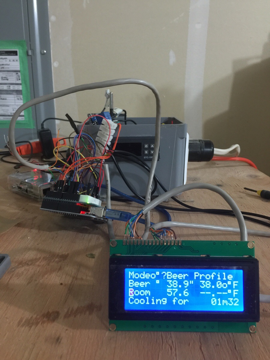
The basic scheme supports the One-Wire bus and the LCD display.
Refer to the original post in this thread for links to the larger pieces.

There are also these support options:
- Bluetooth/Serial Module
- rotary encoder switch
- cool/heat panel LEDs

Parts: Starting with what's included in the Arduino Protoshield V6 (latest/greatest) the additional parts required for the basic scheme are:

- 20x4 white-on-blue parallel-entry display
- 74HC595D
- 10K 3-lead trim pot
- (2) IN4007 diodes
- 20 to 30 ohm resistor 1/2W
- 4.7K resistor 1/4W
- I recommend using 24-26 gauge solid, insulated wire

- optional but recommended: 16 pin IC socket
- optional but recommended: extra .1 UF >10V ceramic capacitors (2 or more)
- optional: extra header pins


Add for Bluetooth/Serial Module:
- 1K resistor 1/4W
- 2K resistor 1/4W

Add for Rotary Encoder:
- (3) .1UF >10V ceramic capacitors
- (3) 10K resistors 1/4W

Add for panel LED support:
- (2) 220 resistors 1/4W


Also, I've included a schematic of the AC switching scheme I'm using. This provides independent On/Off/Auto control for the Cool and Heat AC outlets. This uses a pair of 20A rated DPDT On-Off-On switches and a pair of LEDs along with the Sainsmart dual relay card. All of that is optional.


Building the base Protoshield: There is a tutorial for assembling the Arduino Protoshield here. Unfortunately it is for an earlier revision PC board, but almost all of the instructions still apply.

The kit comes with the parts shown in the first picture below.
I used all parts but the two 1x5 headers and one of the 1x6 headers.

Caution: Note which side is "UP" before starting.
The only part that is installed from the BOTTOM side of the board is the 2x3 stacking header (shown at the left edge in the second picture).

Completing the Build:

I prefer not to use Dupont wires with male ends as they need more air space above the board and are intrinsically fragile. I've done this layout so all wire connections use female Duponts.

The kit comes with a strip of 36 header pins which is enough - if you install them where they are needed. If you have extra header pins on hand you can go nuts like I did, but if you're stuck with just the 36 pins in the kit, I've highlighted the 32 pins that need to be present. These pins match up with the jumper wire connection points in the diagram at the bottom of this post.

The IC orientation isn't optimal wrt the Protoshield etch (IC power and ground pins are on the "wrong" sides of the two bus strips), but was to keep the switching inputs to the IC as short as possible as HC series logic doesn't take well to input ringing.

So there it is. Hopefully there's enough here to successfully construct a protoshield, but feel free to post any questions/issues/objections/suggestions here...

Cheers!

Just having a quick look at my wiring against the one you've provided, i.e as i'm not planning on adding bluetooth and the torero encoder i've taken out what i don't think i need, and i've noticed i'm missing he 10k resistor between Pin 10(?) on the shift register and the 5v rail which i guess explains the no power situation.

in terms of the connection diagram, are pins 3,15,16 one hole to far over on the right on your diagram?

247280d1420685923-how-brewpi-lcd-add-shield_wiring_newest.jpg
 
If you disconnect the AC loads on the relays do you still get display errors?
Do you know if your relay modules have snubber diodes across the coils?
Also, what is the actual 5VDC level at the LCD?

btw, at least one other person has gone through this and I believe eventually solved it.
Hopefully he'll chime in...or you could start digging back through the thread...

Cheers!

Thank you day_trippr..

Yes, even without load i get display errors, but not when there is no AC on the relay!

The relays have diodes:

http://www.ebay.com/itm/221483898972?_trksid=p2060778.m2749.l2649&ssPageName=STRK%3AMEBIDX%3AIT

The 5V level @ the display is 4.98V if the relay is triggered 4.97V..

I also tried to put some distance between the HV part and everything else. No change..

I tested different kinds of relays and its the same, when there is AC power on the relay the display errors appear.

I also tested driving the relay coil over a seperate power supply like in the picture, it should be isolated from the rest but i still get display errors when the relay with AC on it(just a cable but no load) is switched on and off.

Even when the relay is completely disconnected (swiched on off with a seperate arduino) the display gets scrambled.

So the relay generates some EMV which travels trough the mains phase gets into the power supply and ****s up the shift register?

There seems to be some dark magic going on :(

OptoRelayChannelData-575.jpg


DSC_0589.jpg


DSC_0590.jpg
 
hmmm baffled again (becoming very common don't think this kind of project suits me)
really and temp probe seem to work perfectly through the shield but eh display is getting zero power.

i've tried switching power to the LCD using the relay power source to check i've not done something to the 5v, but getting nothing.

I'm guessing either i've missed something. or there is a short, any ideas?

for inför if i swap pins 1,2 and 15,16 the backlight does come on but nothing else and contrast doesn't seem to adjust

ok so i traced the power to the trimmer pot and it turned out i didn't have a good connection between the diode and resistor so i now have power and backlight.

just no text on the display and adjusting the contrast does nothing.
*Edit - my soldering must be so bad, i've got contrast on the screen now, but only two lines of blocks and no text... so frustrating!

Topside.jpg


IMG_9730.jpg
 
Just having a quick look at my wiring against the one you've provided, i.e as i'm not planning on adding bluetooth and the torero encoder i've taken out what i don't think i need, and i've noticed i'm missing he 10k resistor between Pin 10(?) on the shift register and the 5v rail which i guess explains the no power situation.

Pin 10 of the shift register is the low-active hardware reset input.
If you leave that unconnected the shift register will likely be stuck in reset forever.
Which means the LCD will never get initialized, never mind have any characters show up.

So add the pull-up resistor - it can be pretty much any value as noted.

in terms of the connection diagram, are pins 3,15,16 one hole to far over on the right on your diagram?

Good eye - that error lived for weeks ;)

Here's the updated diagram.
And once again, the original post cannot be edited, so this will have to suffice as the official change notice ;)

Cheers!

shield_wiring_newest.jpg
 
[...]Yes, even without load i get display errors, but not when there is no AC on the relay!

[...]The 5V level @ the display is 4.98V if the relay is triggered 4.97V..

I also tried to put some distance between the HV part and everything else. No change..

I tested different kinds of relays and its the same, when there is AC power on the relay the display errors appear.

I also tested driving the relay coil over a seperate power supply like in the picture, it should be isolated from the rest but i still get display errors when the relay with AC on it(just a cable but no load) is switched on and off.

Even when the relay is completely disconnected (swiched on off with a seperate arduino) the display gets scrambled.

So the relay generates some EMV which travels trough the mains phase gets into the power supply and ****s up the shift register?

There seems to be some dark magic going on :(

Holy cow.

"Even when the relay is completely disconnected (swiched on off with a seperate arduino) the display gets scrambled."

This one is mind boggling: the relay power, ground, and controls are not even connected to the same Arduino with the LCD? But you can still punk the display by switching the relay?

Please tell me I'm getting that wrong ;)

fwiw/btw, that black-on-yellow display uses 6 times the VDD current as the white-on-blue version - 180mA typical vs 30mA typical. Make sure you're using a decent gauge wire for the power and ground connections at pins 2 & 1, respectively...

Cheers!
 
[...]also, is there anything that is worth setting via rotary over web interface?[...]

The encoder offers a subset of functions versus the web gui.

If BrewPi is running in Beer Constant or Fridge Constant Mode, you can directly change the target temperature setting.

You can also change the Mode from Off to Beer Constant, Fridge Constant or Beer Profile.

If the Mode is changed to Beer Constant, the cursor will automatically go to the Beer Setting field where you can dial in your desired temperature.

If the Mode is changed to Fridge Constant, the cursor will automatically go to the Fridge Setting field where you can dial in your desired temperature.

Finally, the Mode can be changed to Beer Profile, but it isn't clear how that's supposed to work. I'll have to experiment with that one. I don't think you can use the encoder to build a Profile.

While all these encoder manipulations are going on, the web gui will log any changes (open the log viewer and enable auto-refresh) but it'll take a browser refresh to see the changes take effect...

Cheers!
 
Yes, and there is not even a load connected. The picture from the last post shows the test setup.

I mean the only physical connection goes from the relay trough the mains phase -> transformator -> dc-dc converter -> shift register -> lcd

But how can it generate noise when there is no arc from switching a load.

I mean it must have something to do with the AC because i can switch the unconnected relay without a problem.

Maybe the wires form the rotary encoder act like an antenna?

I never had any trouble with the bluetooth connection or the arduino tough.

Just ordered some SSR, i think i had it with those relays.
 
Pin 10 of the shift register is the low-active hardware reset input.
If you leave that unconnected the shift register will likely be stuck in reset forever.
Which means the LCD will never get initialized, never mind have any characters show up.

So add the pull-up resistor - it can be pretty much any value as noted.


Good eye - that error lived for weeks ;)

Here's the updated diagram.
And once again, the original post cannot be edited, so this will have to suffice as the official change notice ;)

Cheers!

added in the resister at pin 10 i get blocks but no text, getting close to throwing in the towel
 
added in the resister at pin 10 i get blocks but no text, getting close to throwing in the towel

Ok, with this all in place and powered up, are you able to actually communicate with the Uno from the BrewPi gui? Do the probes read ok? Can you toggle relays?

Basically, is the LCD the only thing not working properly right now?

I'm sure we can get through this. Have faith :)

Cheers!
 
Ok, with this all in place and powered up, are you able to actually communicate with the Uno from the BrewPi gui? Do the probes read ok? Can you toggle relays?

Basically, is the LCD the only thing not working properly right now?

I'm sure we can get through this. Have faith :)

Cheers!
yep everything is working relay triggers can connect to brew webgui i just can't get the screen to display anything other than 2 lines of white boxes.

I think it can only be down to my soldering.

the LCD is the only think not working

IMG_9731.jpg
 
added in the resister at pin 10 i get blocks but no text, getting close to throwing in the towel

The picture you posted already had that pull-up resistor in place.
Did you update it when I wasn't looking?

I went through your shield pictures and aside from two soldering issues that you probably found and fixed (backlight power and contrast adjustment). Looks like one of your caps might not be making a good connection as well (the one with its GND connection near IC pin 16).

Also, the view of the under-side of the board - but rotated 180° - the "north" end of the pad for IC pin 14 is obscured by the 5V connection to pin 16, and is surrounded by ground connections. Could you make sure that pad isn't shorting to the ground bus running just north of the pad?

The rest of the shield wiring looks like it should work, so triple check the jumper wires between the shield and the LCD. Make sure all three ground connections are there...

Cheers!

Mikmonken_bottom.jpg
 
Thanks for looking I'll have a look at it tomorrow, I figure it has to be my soldering.

Thanks for taking the time to look, I so determined to get this thing to work, it'll probably end up costing me more than buying the Brewpi in the first place!!
 
Yes, and there is not even a load connected. The picture from the last post shows the test setup.

I mean the only physical connection goes from the relay trough the mains phase -> transformator -> dc-dc converter -> shift register -> lcd

But how can it generate noise when there is no arc from switching a load.


It boggles the mind. Even with the AC connected to the switched point, with no actual load on the relay output I can't imagine how the points could cause electrical noise. It's an open freakin' circuit with an ultra-low-frequency signal source. "WTF, over?"

I mean it must have something to do with the AC because i can switch the unconnected relay without a problem.

Maybe the wires form the rotary encoder act like an antenna?

Disconnect them from the shield. What happens?

I'd be inclined to look elsewhere as those connections don't go anywhere near LCD or shift register. As you've apparently eliminated the actual relay switching (no AC connected) affecting the 5V power distribution - and it would be way the heck over the top to believe the open-circuit AC switching is getting into the DC power - the order of most likely:

- Shift register SCLK (Uno IO 13, S/R pin 11)
- Shift register RCLK (Uno IO 10, S/R pin 12)
- LCD Clock (LCD pin 6, S/R pin 1)
- LCD Register Select (LCD pin 4, S/R pin 15)

These are all "ones catcher" signals - meaning a glitch on any of them will cause "change" without requiring anything else to happen.

This is opposed to the various data signals - the S/R Data input on pin 14 (Uno IO 11) and the four LCD data inputs on punts 11-14 (S/R output pins 4-7). A glitch on any of those will have no effect as the former needs an SCLK transition to do anything, and the latter need an LCD clock to do anything.

I never had any trouble with the bluetooth connection or the arduino tough.

And I've never had anything like what you're seeing - at least on the two boxes that are actually driving my fermentation fridge (heat & cool) and my cold-conditioning/carbing fridge (cool only). Actually, all of these "relays scramble LCD" threads zoom by me 'cuz I can't duplicate the problem with the two closed boxes.

But I don't have AC connected to the open bundle of boards and wires and sensors and LCD and encoder on my desk that is my debug BrewPi Uno. If I have some time tonight I'll hook AC up to the dual relay module and see what happens.

Just ordered some SSR, i think i had it with those relays.

Fingers crossed...

Cheers! ;)
 
Ok, AC hot connected to the switch points for both Cool and Heat relays on a dual relay SainSmart board. Neutral and Safety Ground clipped and insulated.

I went into BrewPi - Maintenance panel - Device Configuration and toggled the Pin Setting for both the Cool and Heat devices from inverted to non-inverted and back a dozen times each. No effect on the LCD.

So now I'm running in Beer Temperature Mode and will see what happens when the relay and LCD both change together on their own when either the Cool or Heat relays are toggled.

All while my education and experience is telling me this is insane...

Cheers! ;)
 
EDIT: NVM I'm dumb. lol. Erased what I wrote.

Doesnt your relay board there have an extra jumper on it though?
 
I've only moved the jumper for the pnp relay driver collectors off its default "same as logic voltage" position when I was doing a survey of the currents used by various elements - including the relay coils. Other than that brief period it's been set to use the same (default position) voltage source used by the opto-couplers.

Note that this is one of my protoshield builds. If I need to hook up the breadboard version, that's probably going to sit in the queue for a bit...

Cheers!


Sorry when I deleted my last post I deleted the quote. I see two jumpers on doomys board. I honestly havent looked at what they do but mine only came with one on it.
 
I'm pretty sure Doomy's using the same 2 channel SainSmart board I've used on all my BrewPi devices.

On that board there's only one actual "jumper" header, and that's the one that if plugged ties the relay driver side (JD-VCC) to the logic power rail ("VCC").
The other header has the inputs to the two optocouplers and the VCC and GND pins...

Cheers! (low-res SainSmart graphic follows)

2 channel.jpg
 
Yeah you're right. I have new glasses at it was a blurry picture. It looked like two rows of headers to me with two jumpers.
 
Disconnect them from the shield. What happens?

I'd be inclined to look elsewhere as those connections don't go anywhere near LCD or shift register. As you've apparently eliminated the actual relay switching (no AC connected) affecting the 5V power distribution - and it would be way the heck over the top to believe the open-circuit AC switching is getting into the DC power - the order of most likely:

- Shift register SCLK (Uno IO 13, S/R pin 11)
- Shift register RCLK (Uno IO 10, S/R pin 12)
- LCD Clock (LCD pin 6, S/R pin 1)
- LCD Register Select (LCD pin 4, S/R pin 15)

These are all "ones catcher" signals - meaning a glitch on any of them will cause "change" without requiring anything else to happen.

This is opposed to the various data signals - the S/R Data input on pin 14 (Uno IO 11) and the four LCD data inputs on punts 11-14 (S/R output pins 4-7). A glitch on any of those will have no effect as the former needs an SCLK transition to do anything, and the latter need an LCD clock to do anything.


I had that in mind when i designed the 2nd version of the PCB.The PCB is directly attatched to the LCD so cable length to and from the shift register is minimized. I was shocked when i still got the display errors from the relay switching.

Tried without rotary encoder wires, same error.

Good idea to just switch inverted non-inverted for testing, havent had thad come to my mind..

I wonder if it has anything to do with my GND wireing, should i connect the arduino mini only at one GND point?

More pictures:
https://doomlab.wordpress.com/2015/02/20/brewpi-improved-version/

Screenshot 2015-02-18 18.01.35.png


Screenshot 2015-02-18 18.01.00.png


DSC_0586.jpg


Screenshot 2015-02-20 06.48.20.png
 
I think my board may need pulling apart and reassembling I just can't get it to work... But fortunately the temp probes and cooler work direct from the shield so for the time being ill just use it without the screen.
 
Doomy86

I don't know the exact power requirements for the screen and the mini. But it looks like you're depending on a 7805 to provide you with 5v. You are only capable of getting 1.2-1.5 amps nominal this way. I assume this is because your power supply is 12-24v. I wonder if your design would work better if you just brought 5v in directly from a 5v source. Preferably around 2amps or better.
 
Diomy8


Doomy86. I see you sure using the pro mini. How hard is it to program using brewpi. I thought that unit didn't have an onboard bootloader? Do you have to hit reset every time you program?
 
@wbarber69
I use my arduino uno to programm the mini.. Just connect 5V RX TX and RST to the equivalent pins on the pro mini and run the programmer.

Programming does not work over bluetooth tough..

It can be powered by 5V, just use the pin right next to the 7 - 12V input.
 
@day_trippr

I'm having a hard time with the switching on the AC side. In the ON position, why connect the LED cathode to D5? Wouldn't this be variably High or Low, depending on what is actually happening on the controller side, which is actually being bypassed? Am I looking at this wrong? The other side is connected to Ground in the auto position, but then it would always be on because the LED pull up is attached to +5v. Are those swapped on the diagram?
 
Bingo. Stupid engineer documentation trick ;)


The grounds versus control signals were swapped at their respective switch inputs. Here's the corrected drawing...


Cheers!


Hah. Thank god. I was banging my head against the wall thinking there was some kind of logic I was missing. Thanks again. Soldering up my proto right now.
 
Bingo. Stupid engineer documentation trick ;)

The grounds versus control signals were swapped at their respective switch inputs. Here's the corrected drawing...

Cheers!

Is there a reason you chose to bypass the relay board for the switching and go AC instead of DC? I feel like bringing in 5v into the switch and outputting to the relay board would be easier and could use much smaller toggles. I don't have anything rated for 10A as far as toggles go, so I'll probably go that route unless you can think of a reason why I shouldn't?

And for clarification, do D5/D6 go High or Low to engage the relays? Obviously that would change the switching schematic for me.
 
My intention for the manual modes is to bypass as much as possible.
Relying on the relays to be functional goes against that goal.

I patterned this after my Love TSS2 implementation (same box, switches, duplex outlet, AC ingress, just different control guts) which has worked out well.

The SainSmart relay modules require low levels on the two optocoupler inputs to energize the relays, so actuators D5 & D6 are configured in BrewPi to be active low...

Cheers!
 
If you want to employ the relays all the time you can use a very light duty SPST center-off toggle switch instead of the 20A rated DPDT center-off switches I used.

Then you would put the control output from the Uno (eg: D5) on one pole, a connection to logic ground on the other, and then connect the common to the relay module input.

So with the switch in one position it's routing the Uno control to the relay, in the other it simply drives the same relay control to ground, and in the center-off position the relay input would float high and thus would be "off".

Do that for both stages (cool and heat, using D5 and D6, respectively) with a pair of switches and you'd be in business...

Cheers!
 
I have everything setup, and almost running right. I cannot figure out how to wire up my rotary encoder. I was able to figure everything else out based off of the wiring diagrams, but for my encoder it doesn't make any sense to me so far. My encoder has three pins (A,B, and common I assume) along with the two for the push button. If I understand correctly, I need to ground the common pin, and one of the push button pins. The rest has me lost. I see that three resistors and three caps seem to be required to use it, but how do I wire those up to the encoder pins?

Here's my progress so far, it's quite a mess, but it's working and I know what everything is so far. The protoshield I got on Amazon was crap, it's designed for a completely different setup, so I'm using a breadboard on top until my other protoshield gets here from China, then I can solder it up and mount it behind my fermenter. Thanks to all who have put this together so far!

7w9955X.jpg
 
Wire the common for the rotary encoder side to either of the two pins on the other side, then connect that to any handy Ground pin on your shield board.

The other three pins connect as shown here.

247280d1420685923-how-brewpi-lcd-add-shield_wiring_newest.jpg


Don't worry if you can't figure out which of the two encoder pins goes to which AVR pin - just connect them to IO 8 & 9. When you try it out, press the push button and set the Mode to Beer Constant, then when you adjust the Beer Temperature goal you'll see if turning clockwise increases the value or decreases it. If it decreases, swap your connections to IO 8 & 9...

Cheers!
 
Thank you, that worked great! It even fixed the weird characters on my LCD for some strange reason. So is that filtering circuit for the encoder on your original wiring diagram not needed?
 
Wire the common for the rotary encoder side to either of the two pins on the other side, then connect that to any handy Ground pin on your shield board.

The other three pins connect as shown here.

247280d1420685923-how-brewpi-lcd-add-shield_wiring_newest.jpg


Don't worry if you can't figure out which of the two encoder pins goes to which AVR pin - just connect them to IO 8 & 9. When you try it out, press the push button and set the Mode to Beer Constant, then when you adjust the Beer Temperature goal you'll see if turning clockwise increases the value or decreases it. If it decreases, swap your connections to IO 8 & 9...

Cheers!

having seen rcm_rx7 post above, does the addition of a push button rotary encoder act as a reset for a scrambled display?

I am now waiting on protoboard number 3 and 4 to arrive so i can have a 3rd/4th attempt i've orders some from Aliexpress so they'll take a month to arrive but they were dirt cheap, although they're the Arduino and not sainsmart style boards, so i'll have to reconfigure the layout slightly.
 
OK so i've tried to remap the original layout onto the arduino protoboard id' love to keep using the v6 board as it looks like the cheap boards i've got coming from China require a lot more connections. but hey they're cheap.

Also being pretty much electronically illiterate i've used fritzing and my WYCIWYG design. i think i've mapped the components and connections pretty accurately, i've not added in bluetooth or the rotary encoder although i think this would be great to add at a later date.

can anyone see anything that shouts "it'll never work"

here's a link to the shared friztzing sketch too, i figure i should probably change the resistor colours to make it easier to follow.

also the resistor under the shift register i plan to run under the board between the 5v an the pin

Screen Shot 2015-02-27 at 09.49.04.png
 
having seen rcm_rx7 post above, does the addition of a push button rotary encoder act as a reset for a scrambled display?


I am now waiting on protoboard number 3 and 4 to arrive so i can have a 3rd/4th attempt i've orders some from Aliexpress so they'll take a month to arrive but they were dirt cheap, although they're the Arduino and not sainsmart style boards, so i'll have to reconfigure the layout slightly.


Well when I woke up this morning it was back to a few scrambled characters, the same ones in my picture above. Using the encoder did not change that at all, a reset of the arduino fixed it.

My arduino is powered through USB, and I measure a little over 5v at all points on the protoboard, though that may change a little when the relays kick on, I haven't tested that. I have a 12v power supply I can wire into the arduino, and I can also shorten up the wires from the register to the LCD, as they are about 3ft in length right now. I'm not too concerned as this is all still mounted on a breadboard, and my good protoshield won't be here for a few weeks. I will definitely update with my results though.
 
Back
Top