HLT build help

Homebrew Talk - Beer, Wine, Mead, & Cider Brewing Discussion Forum

Help Support Homebrew Talk - Beer, Wine, Mead, & Cider Brewing Discussion Forum:

This site may earn a commission from merchant affiliate links, including eBay, Amazon, and others.

tnbrewer371

Well-Known Member
Joined
Mar 12, 2010
Messages
333
Reaction score
12
Location
Nashville, Tennessee
I am trying to design and build an electrically fired HLT that will run off an inkbird temp controller. My idea is to design and build an HLT minus the HERMS coil as laid out on the electricbrewery website, except using a 120V/2000W element. Can I build my HLT as described on there only using a camco 120v/2000W element, and in line wire a 120v 30A relay Such as:

Zettler Miniature Power Relay 30A SPDT 120VAC AZ2280-1C-120A https://www.amazon.com/dp/B0030G8SC8/ref=cm_sw_r_cp_api_fabt1_nSiUFbTJ60P71

And power the relay using my inkbird controller. The idea is to be able to turn the controller on using a smart switch at a specific time, to get my mash water up to temp for when I wake up, and am ready to dough in. the relay would cycle on and off from the inkbird controller to keep the water at my desired mash in temp. The inkbird controller would also control a pump to recirculate water in the hlt. I guess my questions are:
1. Does this sound reasonable?
2. Will this relay work for this application?
3. How do I wire the relay to a plug to attach to my inkbird?

I appreciate all the help as I navigate into electric brewing step by step. I’m a big fan of DIY and trying to use what I have to make the brewing process easier. This step alone could easily cut forty minutes off my brew day and also I’ll be able to heat sprage water (maybe) while I mash. Thanks
-TNbrew
 
There's a lot of things that are less than optimal about your design. Let me show you this, which does everything you want.

I get the idea of wanting to DIY, but I have spent a sh*tton more than that on stuff I have piled on my shelves, never used. :)
Except OP wants to control a 2000W element (16.7A @ 120V), and the IPB-16S is only rated for 15A @ 120V. It is probably possible to come up with a hack to boost the output current, but that ruins the plug 'n play simplicity of this controller.

Brew on :mug:
 
Minor detail! Cunningham's law dictates you give the right answer when you correct me, Doug. :)

Good point - "easy" therefore is to use a ~1200 watt element. Times look like:
  • 10 gallons
  • 60 degree start
  • 165 degree finish
  • 1200 watts
  • 2 hours, 9 mins
 
Could you explain what is less than optimal about my design? I’m not being defensive honestly just wanting to learn more about electric systems.
 
Well first of all: I used to ski at Alta. THAT is superior in all ways to Snowbird. :)

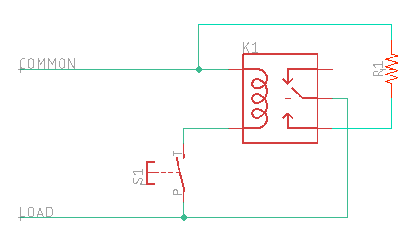
Second, I read your post incorrectly and what you propose will work if that's how you want to go, this is the wiring:

1606055168391.png

Where:
  • S1 is your Inkbird
  • K1 is your relay
  • R1 is your heating element
As Doug said, your load here is 16.7A for the element, so you will want a dedicated (or lightly traveled) 20A circuit for the heater.

I don't know which controller you have, so I can't give you a specific "this is how you do it with your stuff" but that schematic should help.
 
I have an inkbird itc308 but I’m thinking of purchasing a dedicated inkbird itc1000 to dedicate to this purpose as my 308 runs my fermentation chamber mostly. Trying not to collect even more brewing gear than I already have, so my wife can’t say “I thought you said you wouldn’t ever need anything else for the brewery”, she really doesn’t care just likes to tease me when I’m wrong as I’ve said that a hundred times probably. I digress, I’m still semi unfamiliar with the schematic you’ve provided, I’m sure I can sort through it if I take some time unless you care to expand on it a bit. Thank you so much for your help sir, this forum has been fantastic over the course of my brewing career I feel as if I’d been lost without it! Cheers! -TNBrew
 
Happy to help - and I have to say at this point I am "noodling" and not prescribing a particular direction. I also may offend you if I go too basic, so for that, I apologize. It will help anyone else coming and reading this.

Household current in the US is ~120VAC, single-phase. That means one lead is "hot" and one is "common" (generally bound to ground in the circuit box.) Therefore we only need to switch one leg of the circuit and the circuit is relatively safe. In my diagram, I am splitting the hot between the switch (the controller) and the relay. At the relay, the hot side comes into the common post, and the element is connected to the NO (normally open) post. In this way when the switch (controller) is active, the coil pulls down, and the relay connects common to NO. The other side of the element is connected to the house wiring common creating an energized circuit.

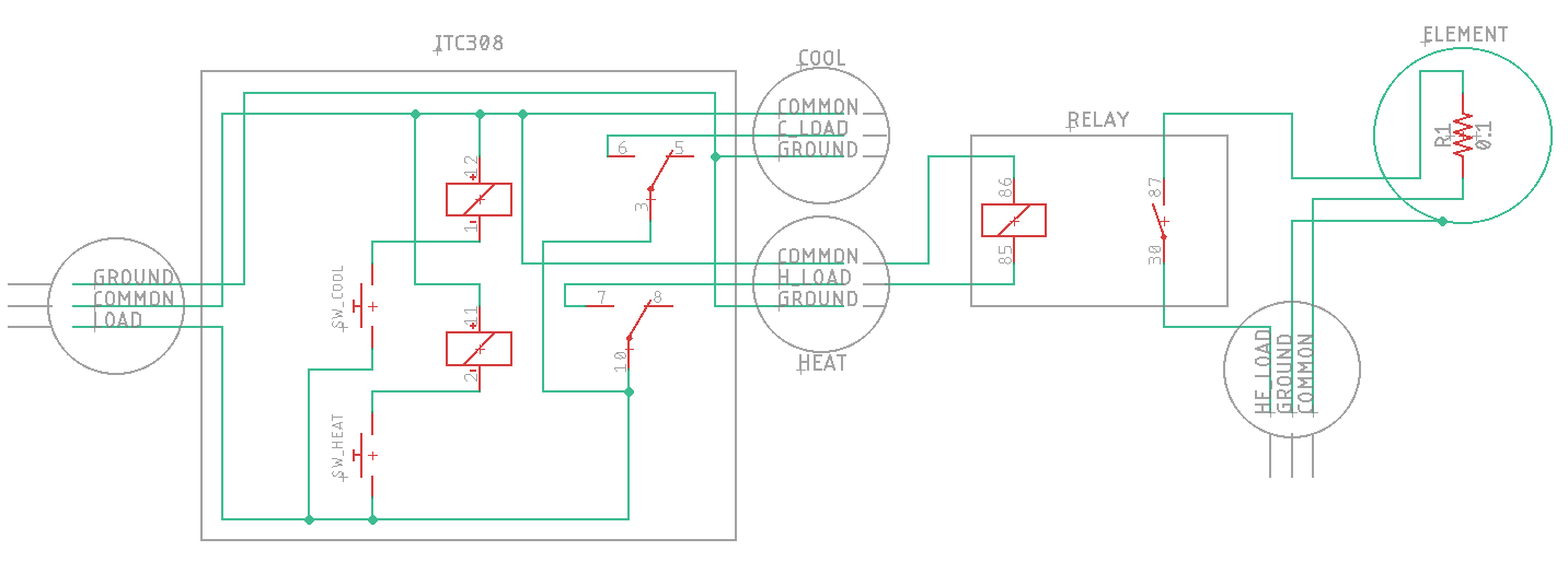
So you have an ITC308 which basically creates that circuit above with the addition of a second circuit for cooling. With the exception of not depicting "off", it looks a little like this:
1606061983084.png

You have probably figured out the ITC308 has a max output of 1100W. One way to go would be to simply use a 1000W heating element. Your heating time looks like this:
  • 10 gallons
  • 60 degree start
  • 165 degree finish
  • 1000 watts
  • 2 hours, 35 mins
This meets your goal of heating your water overnight. Note that this calculation does not take into account any losses, so you would need to insulate your HLT very well.

If you want to "go bigger" then as you assumed you need an additional relay. That will wire in like this:
1606061899895.png

Either of those relays you shared would work I think. Basically, you need a 120VAC relay rated for 120VAC load > 20A.
 
Last edited:
Could you explain what is less than optimal about my design? I’m not being defensive honestly just wanting to learn more about electric systems.
The InkBird ITC308 (as well as the ITC1000) are both on/off controllers with hysteresis. If the temp is below the setpoint by the lower hysteresis limit (which is adjustable) then the heat relay turns on. When the temp reaches the set point, the heat relay turns off. The heat does not come back on until the temp drops below the lower hysteresis limit again. Thus temp of the water in your HLT will vary between your two temperature limits. If this is acceptable to you, then your plan will work fine.

On the other hand, if you want to maintain the HLT water temp at a tightly controlled, fixed temperature, then you need to use a PID, or similar, controller. These controllers can (if tuned correctly) eliminate the temperature cycling of water. The InkBird IPB-16S is a PID controller. PID controller typically turn the power on and off at a much faster cycle time (1 - 2 seconds) than do hysteresis controllers (cycle times of minutes.) Because of this, PID controllers for heating elements usually use solid state relays (SSR's) to control power to the element, since they are not subject to mechanical fatigue or contact erosion as are mechanical relays.

Brew on :mug:
 
A two or three degree variance would be acceptable me. I’m familiar with how the inkbird works as I’ve been able to experiment with it with my full size (top/bottom) refrigerator fermentation chamber. Ideally I’d end up insulating my HLT at a later date once I know the project is reliable. A couple degrees off in strike water temp has never concerned me, nor seemed to make a difference in my final product. Does anyone know which of the two products above would work better? It seems to be the second I posted, the two pole contacter seems better suited but I’m a complete novice in this. Can I just use an old extension cord to as my line from my inkbird plug to the contactor/relay?
 
A two or three degree variance would be acceptable me. I’m familiar with how the inkbird works as I’ve been able to experiment with it with my full size (top/bottom) refrigerator fermentation chamber. Ideally I’d end up insulating my HLT at a later date once I know the project is reliable. A couple degrees off in strike water temp has never concerned me, nor seemed to make a difference in my final product. Does anyone know which of the two products above would work better? It seems to be the second I posted, the two pole contacter seems better suited but I’m a complete novice in this. Can I just use an old extension cord to as my line from my inkbird plug to the contactor/relay?
Hope I didn't offend you by being too basic. It's often hard to know what level of background someone else has on the internet, and talking below them or above them is all too easy to do.

For a 120V system, a two pole contactor/relay is not necessary (it is with split phase 240V as used in the USA and elsewhere.) So the relay in your first post would work just fine. Yes you can use an old extension cord from your InkBird to the relay coil. You should put the relay in some type of enclosure to prevent fingers, or other things, from coming into contact with the terminals.

Brew on :mug:
 
Darn it, Doug! Ya beat me to it!

I agree with Doug - and wiring it with your existing InkBird would be simplest for you and get you running quickly. Generally speaking the 1/8 DIN PID controllers switch low-voltage so you would have to add a power supply in addition to the high-voltage wiring.
 
Guys thanks you so much. And you can’t offend me. I don’t have time to be offended when I could be learning from someone wiser then me and I’m most definitely a novice and not afraid to admit the fact. Okay so the plan is to use my existing inkbird and scavenge an old extension cord to wire into the contactor to close the circuit to run the 120v to the 2000w element in my hlt. Solid plan?
 
Guys thanks you so much. And you can’t offend me. I don’t have time to be offended when I could be learning from someone wiser then me and I’m most definitely a novice and not afraid to admit the fact. Okay so the plan is to use my existing inkbird and scavenge an old extension cord to wire into the contactor to close the circuit to run the 120v to the 2000w element in my hlt. Solid plan?
Should work.

Brew on :mug:
 
But I could use a double pole now only using one pole and have it for later when I get my 240 volt Run For a future EBK and use it in the same manner right?
 
If you really only want electrics and control to heat the water to a general target temp +/- a few F, a power relay where the coil is powered by the "heat" output of the Inkbird 308 is just fine. Just keep in mind you need a 20 amp circuit and from the receptacle you want 12/3 cord running to the line terminals of the relay and 12/3 cable running to the load/element. You should use a GFCI protected 20 amp wall receptacle before the control box with the relay in it.

If you think you'll ever want to use the HLT for a HERMS, you'll benefit from just building a slightly more complicated controller with a PID at the helm.
 
I think I’m just gonna use a general all purpose inkbird to send a relay to a contactor to turn on and off the 2000W element. I like the controller above but it doesn’t look like it will give me the output I need to run the element I want. I have a 20 amp line with a gfci outlet I plan to use. I know the element is gonna pull 16.7 amps, Can I plan to use the inkbird as well on this circuit? Any idea how many amps I can expect to draw with the inkbird and contactor?
 
I like the controller above but it doesn’t look like it will give me the output I need to run the element I want.
It's right at the edge, you are correct, this is not enough.
I have a 20 amp line with a gfci outlet I plan to use. I know the element is gonna pull 16.7 amps, Can I plan to use the inkbird as well on this circuit? Any idea how many amps I can expect to draw with the inkbird and contactor?
Do you mean will the 20A circuit run the circuit + the Inkbird + the contactor? I'd say yes. If you find it's an issue you can always power the Inkbird and contactor off a separate circuit.
 
I think I’m just gonna use a general all purpose inkbird to send a relay to a contactor to turn on and off the 2000W element. I like the controller above but it doesn’t look like it will give me the output I need to run the element I want. I have a 20 amp line with a gfci outlet I plan to use. I know the element is gonna pull 16.7 amps, Can I plan to use the inkbird as well on this circuit? Any idea how many amps I can expect to draw with the inkbird and contactor?
The InkBird + contactor (no need for another relay, just use a contactor w/120V coil) will draw less than 1/2 A. So, there shouldn't be any issue.

Brew on :mug:
 

Latest posts

Back
Top