• Please visit and share your knowledge at our sister communities:
  • If you have not, please join our official Homebrewing Facebook Group!

    Homebrewing Facebook Group

Fundamental 220v question on my elec. HLT/HERMS setup

Homebrew Talk

Help Support Homebrew Talk:

This site may earn a commission from merchant affiliate links, including eBay, Amazon, and others.

JYoder

New Member
Joined
Oct 16, 2014
Messages
2
Reaction score
0
I'm in the parts & materials gathering stage of my electric HLT build to which I will incorporate a HERMS system later. I plan on installing a 4500 element into an aluminium kettle I've used for my 5 gal. gas fired brews in the past. I'm ready to proceed with installing a dedicated 220v GFCI circuit [via a spa panel from home depot] to service the new setup [an endeavor I'm familiar and comfortable with]. My desire to stay alive and ensure the electrical safety of those near me, brings me to a few fundamental questions when wiring up the PID, SSR and the element for 220v:

1. There are 2 terminals on the element. The schematics I see around the web point to one leg of the 220 supply being run directly from the service to one of the terminals; and the other ran through the SSR [ending at the other terminal]. Is this correct?

2. I see some setups using "contactors" between the SSR and the Element? What is the purpose of a contactor and how is it used correctly in a basic setup?

3. I have a 50 amp dedicated circuit feeding the 50amp GFCI spa panel. Is it safe to use 30 amp rated wire/connectors from this point out to the element? A run likely to be as far as 40-50 feet.

Lastly, this is my first go at seeking the guidance of my fellow homebrewers. I have learned nearly all I have from this very site. Thank you to those that have contributed their advice and those that have asked such specific questions; many of which I have had myself and had answered so well right here. I appreciate the consideration of anyone that can help guide me on this project.

1) Yes.
2) SSRs can leak some current and fail closed (on). A normally open contactor will ensure that there is no power to the element unless the contactor is switched closed. This provides safety in that you will kno2 that off means off.
3) Absolutely not. The breakers are to protect the wire. 30a wire could catch fire before the circuit breaker opens at 50a. You will either need 50a rated wire, or better, additional circuit breakers or fuses in your control panel to allow you to step down to lower rated wire. What are you planning to have in your control panel?
 
3) Absolutely not. The breakers are to protect the wire. 30a wire could catch fire before the circuit breaker opens at 50a. You will either need 50a rated wire, or better, additional circuit breakers or fuses in your control panel to allow you to step down to lower rated wire. What are you planning to have in your control panel?


It's not true. You can't make 10awg wire to catch a fire under 50amp load.

EDIT: OK let say "Under normal circumstances you can't make 10awg wire to catch a fire under 50amp load".

If you take a long 10awg cord make a coil from it, put it in small very well thermal insulated box , add some highly flammable material inside and ran 50Amp through this cord than you will have some chance to make a fire.
 
3. I have a 50 amp dedicated circuit feeding the 50amp GFCI spa panel. Is it safe to use 30 amp rated wire/connectors from this point out to the element? A run likely to be as far as 40-50 feet.

I assume the run at 30 amps is not 50ft from your spa panel. At any rate, why use wire rated for 60% of the circuit load without consideration of voltage drop and thermal loading? Fuses are cheap. Use a 30 amp fuse at the transition.
 
It's not true. You can't make 10awg wire to catch a fire under 50amp load.

EDIT: OK let say "Under normal circumstances you can't make 10awg wire to catch a fire under 50amp load".

If you take a long 10awg cord make a coil from it, put it in small very well thermal insulated box , add some highly flammable material inside and ran 50Amp through this cord than you will have some chance to make a fire.

Sure, not likely under normal circumstances, but you are not recommending that he wire his panel with 10 awg and 50a overcurrent protection, are you?
 
3. I have a 50 amp dedicated circuit feeding the 50amp GFCI spa panel. Is it safe to use 30 amp rated wire/connectors from this point out to the element? A run likely to be as far as 40-50 feet.

You're going to have your control panel 40-50 feet away from your boil kettle or HLT? That doesn't sound right.

I think you meant to say that your control panel is going to be 40-50 feet away from your GFCI sub-panel.

A 240v/4500w element draws about 19 amps. 2 pumps would draw about 4 amps, tops. PID's and lighted buttons and displays draw less than an amp, so you're looking at a 24 amp draw, provided that you don't turn on both heating elements at the same time. So yeah, wiring for 30 amps would be fine.
 
Sure you can go 30amp (I'd put a breaker to step down, but hey it's your house)...

But if you already have 50amp service why not use it and build a 50A system, which will let you use two (4500) elements at once. Not an earth shattering improvement but pretty handy.

http://www.theelectricbrewery.com/forum/viewtopic.php?t=25793


Sent from my iPhone using Home Brew
 
Sure, not likely under normal circumstances, but you are not recommending that he wire his panel with 10 awg and 50a overcurrent protection, are you?

This is an amateur forum. Everybody can express it's own opinion and it's up to you wisdom to follow it or not.
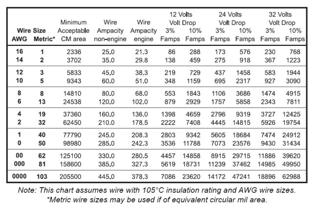
So my opinion : American electrical code is extremely conservative. For example European standards allow to use wires similar to 10AWG for 50AMp load. Same for marine standards. See table attached.


Usually when you have critical panel failure like insulation damage and shortage you will have a more than 50 draw and your 50Amp breaker will be engaged.
Failure when your panel start drawing more than 30Amp but less than 50Amp is extremely rare. And even it happened 10AWG wires will handle that load with no problem.
So I not recommend to use 10AWG for wiring controllers to handle regular 50AMP load but I beleive it's absolutely safe to use 10AWG wire for 30AMP controller with 50Amp protection.

MarineWireChart.jpg
 
If you only plan to use one element and feed your pump(s) off of a separate circuit, you can use 10/3 SJOOW cable. If you want the panel to have 120v for a pump, you'll need 10/4 SJOOW. If you do use 10 gauge, it's best to swap the main panel breaker for a 30 amp. Anyone can find an ampacity chart out on the internet like the one above, but since it mentions 105C rated insulation and 12,24,32 volts, it's most likely a rating for DC application. Either way, most SJ type portable cable is only rated for 90C. Why not stick to the rated ampacity direct from the horse's mouth: http://www.southwire.com/ProductCatalog/XTEInterfaceServlet?contentKey=prodcatsheet281

By all means, if you think you're going to want to run two elements at the same time, use 6 gauge wire. At 50' of run, that is going to sting your wallet a bit. That would be a good reason to use a separate feed for the 120v so you can get away with 6/3.


It seems there are a lot of people chiming in lately regarding what wiring techniques you can get away with.
 
If you do use 10 gauge, it's best to swap the main panel breaker for a 30 amp.

It seems there are a lot of people chiming in lately regarding what wiring techniques you can get away with.

I completely agree with Bobby that using a 30amp breaker in the main and using the 50amp GFCI is no doubt the most sensible and cost effective way to go in this case. You would have 30amp current overprotection and GFCI.

Apparently it is all about saving a few bucks vs doing it the proper way. Sure, the wire can handle it. However, most failures I have seen are in the connections and splices. Those are often overlooked. Scorch marks on connectors and burned insulation proves the wire can handle it. Why not just run your home water heater on a 50amp breaker and using 12ga wire. The wire won't burn.

Edit: NFPA, charges for the NEC code book, and it has no governance of non-permanent household wiring. However, many State resources publish those codes for no charge since they are public law documents if adopted by the State. Seek out state resources, and even public libraries to at least look at proper recommendations. Do not expect to understand them if you don't have a basic understanding of wiring. When in doubt, follow code. What is the downside?
 
Discussions of owner installed wiring shortcuts reminds me of stories I hear about electrical fires, insurance investigators, and unpaid claims for property damage due to a substandard installation by the owner trying to do it on-the-cheap.

So-not-worth it.
 
Back
Top